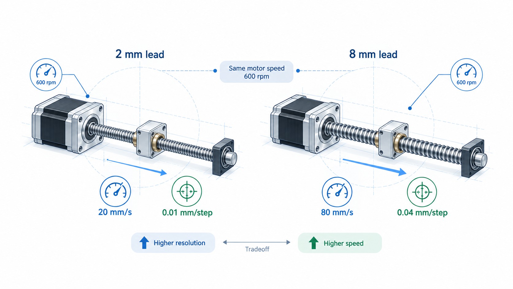
That is why two linear actuators built around the same NEMA 17 motor can behave very differently. A 2 mm lead may provide fine theoretical resolution and high mechanical advantage, while an 8 mm lead can deliver four times the linear travel per revolution. The faster lead can reduce the required motor rpm for a given linear speed, but it also changes available thrust, back-driving tendency, pulse requirements, wear behavior and sensitivity to load disturbances.
For an OEM buyer, machine designer or automation engineer, the real question is therefore not simply, “Which NEMA size do I need?” It is:
Which combination of motor frame, winding, screw lead, screw diameter, nut design, support condition and feedback architecture will meet the required thrust, speed, stroke, accuracy and service life with enough engineering margin?
This guide provides a practical selection method for lead screw stepper motors, stepper motor linear actuators, external and non-captive designs, captive actuators, ball screw steppers and closed-loop linear steppers. It also explains the calculations behind lead selection, thrust, critical speed, screw buckling, backlash and positioning accuracy so that engineering and purchasing teams can compare products on a common basis.
For broader motor sizing before choosing the screw mechanism, see FRANK HU MOTOR’s . For driver selection after the mechanical design is defined, see .
What Must Be Defined Before Selecting a Linear Stepper Motor?
A useful linear stepper motor specification starts with the machine requirement, not with a motor catalog. Before comparing part numbers, collect the following data.
| Selection input | Typical unit | Why it matters |
|---|---|---|
| Moving mass | kg | Determines inertial force and, on vertical axes, gravity load |
| External process force | N | Adds directly to required axial thrust |
| Axis orientation | Horizontal / vertical / inclined | Changes load calculation and back-driving risk |
| Stroke | mm | Affects screw length, critical speed, buckling and actuator architecture |
| Maximum linear speed | mm/s | Determines required screw rpm from the selected lead |
| Acceleration time | s | Determines inertial force and acceleration torque |
| Duty cycle | % | Affects motor temperature, nut wear and lubrication requirements |
| Required repeatability | mm | Helps determine standard nut, anti-backlash nut, ball screw or feedback need |
| Required absolute accuracy | mm over travel | Requires consideration of screw lead accuracy, thermal growth and calibration |
| Load direction changes | Yes / no | Determines how important backlash is |
| Available supply voltage | VDC / VAC | Strongly affects stepper torque at higher speed |
| Controller pulse capability | pulses/s | Must support the selected microstep ratio and maximum rpm |
| Environment | Dust, cleanroom, vacuum, temperature, chemicals | Influences screw and nut material, sealing and lubrication |
| Desired life | hours, cycles or km | Determines load margin and screw/nut technology |
THK uses a similar system-level approach in its , asking designers to define orientation, moving mass, friction, external axial load, stroke, speed, acceleration, positioning accuracy, repeatability, backlash, minimum feed amount and motor characteristics before choosing the screw.
The same logic applies to a lead screw stepper motor. If a supplier is asked only for “a NEMA 17 linear motor,” there is not enough information to make a reliable engineering selection.
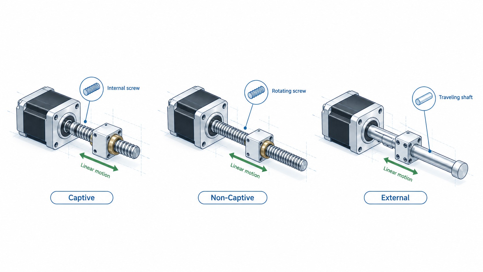
Lead Screw Stepper Motor Architectures: Captive, Non-Captive, External, Ball Screw and Closed Loop
The term linear stepper motor covers several mechanical architectures. Choosing the correct architecture is often as important as choosing the lead.
External Linear Stepper Motor
In an external linear stepper motor, the screw rotates with the motor shaft and a traveling nut moves along the screw. The nut is connected to the machine carriage or moving component.
This layout is familiar to machine designers because the linear motion is visible and mechanically accessible. It is well suited to adjustable stages, dispensing equipment, small CNC mechanisms, laboratory devices and compact automation.
Advantages include:
-
straightforward mechanical integration;
-
easy connection of the nut to a carriage;
-
flexible screw length;
-
easy use of anti-backlash nuts; and
-
intuitive inspection and maintenance.
The designer must, however, consider screw whip and critical speed because the screw itself rotates. As stroke increases, unsupported screw length becomes increasingly important.
A representative FRANK HU MOTOR example is the , which uses a traveling POM nut on an 11 mm diameter screw.
Non-Captive Linear Stepper Motor
In a non-captive linear stepper, the threaded nut is integrated into the motor rotor. The screw passes through the motor and translates when it is prevented from rotating. This can create a very compact axis because the screw passes through the motor instead of extending only from one side.
Non-captive designs are useful when:
-
the mechanism can prevent screw rotation;
-
packaging depth is limited;
-
the application needs a long customizable screw;
-
the motor can remain stationary while the screw moves; or
-
a compact actuator is preferred over a motor-plus-coupling-plus-separate-screw assembly.
The machine designer must provide an anti-rotation feature for the translating screw or attached load. Without anti-rotation, the screw may rotate instead of translating as intended.
Captive Linear Stepper Motor
A captive linear actuator mechanically constrains the translating shaft so that it cannot rotate. It normally provides a defined stroke from the motor body and is easier to integrate when the machine cannot provide its own anti-rotation mechanism.
Captive designs can be attractive for valves, clamps, shutters, medical devices, compact positioning mechanisms and controlled push/pull motion. The main trade-off is that stroke is usually more limited by the internal mechanical construction.
For example, FRANK HU MOTOR lists a . Its specified travel is 3 mm per revolution and 0.015 mm per full step with a 1.8° motor.
Ball Screw Stepper Motor
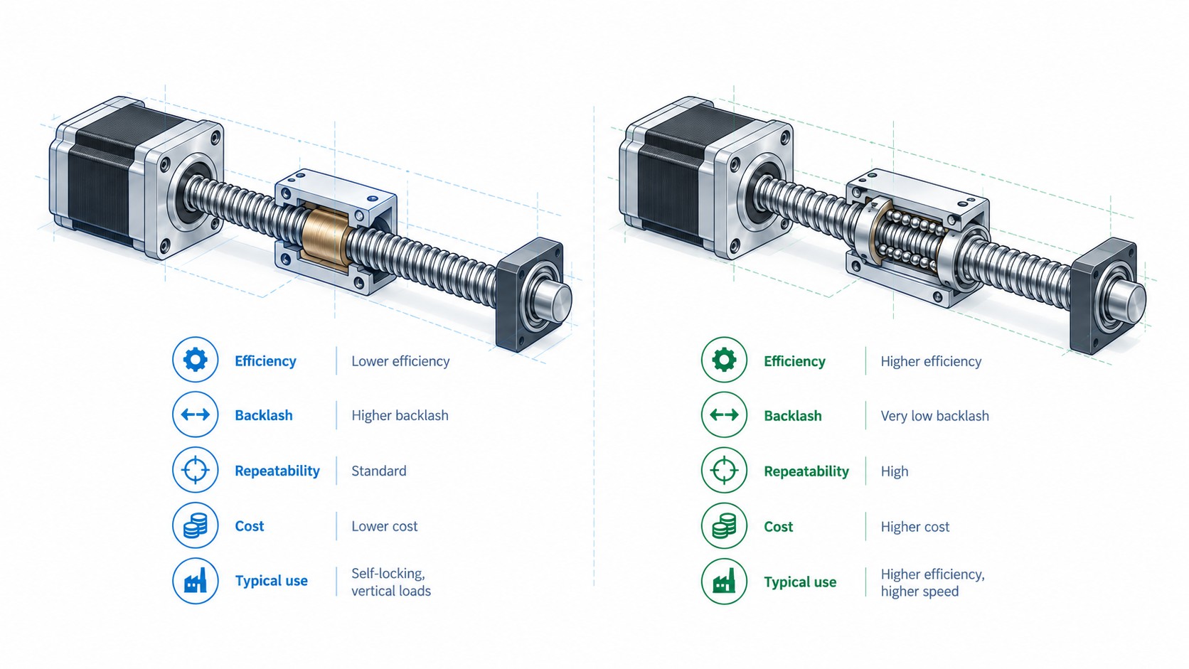
A ball screw stepper motor replaces sliding thread contact with recirculating balls. The main engineering reasons to select a ball screw are higher efficiency, lower friction, higher axial rigidity options, better suitability for high duty cycle, and the possibility of very low backlash through preload.
THK explains that ball screws use rolling contact and can require roughly one-third the driving torque of a conventional sliding screw in its comparison example. THK’s calculation example uses a ball screw efficiency of 0.96 versus 0.32 for a sliding screw, illustrating how dramatically the transmission technology can change required torque. See THK’s .
FRANK HU MOTOR offers configurations such as a and .
Closed-Loop Linear Stepper Motor
A closed-loop linear stepper adds an encoder to monitor motor position. This does not automatically remove lead screw backlash or screw lead error, but it can detect motor position error, reduce the risk of undetected step loss and improve robustness when load varies.
A closed-loop stepper is particularly useful when:
-
the machine cannot tolerate silent missed steps;
-
acceleration or process load varies significantly;
-
the required speed approaches the practical limit of an open-loop stepper;
-
diagnostics and fault detection are important; or
-
the machine needs stronger confidence that commanded motor motion was actually achieved.
FRANK HU MOTOR’s combines a 10 mm lead screw with a 1000 PPR incremental encoder. For a broader control-system comparison, see .
Linear Actuator Module
A complete linear actuator module typically integrates the motor, screw, nut, bearings, linear guide and structural housing. The module costs more than a bare linear stepper motor, but it reduces mechanical engineering work and controls alignment, guide stiffness and contamination more predictably.
For OEM equipment, this can reduce total project risk even if the purchased component price is higher.
| Architecture | Main strength | Main design concern | Good application fit |
|---|---|---|---|
| External | Flexible and easy to integrate | Rotating screw critical speed | CNC auxiliaries, stages, dispensers |
| Non-captive | Compact through-motor screw | External anti-rotation required | Instruments, compact automation |
| Captive | Self-contained anti-rotation | Stroke usually limited | Valves, clamps, short-stroke mechanisms |
| Ball screw | High efficiency and rigidity | Higher cost, lubrication and preload considerations | High duty cycle, precision axes |
| Closed-loop | Detects motor position error | Encoder does not remove mechanical backlash | Variable load and higher reliability axes |
| Complete module | Fastest system integration | Size and cost | OEM machines needing turnkey linear motion |
Lead Is the Most Important Mechanical Ratio in Linear Stepper Selection
The lead of a screw is the linear distance traveled per one revolution of the screw. It should not be confused with pitch in every case. On a single-start screw, lead and pitch are equal. On a multi-start screw, lead equals pitch multiplied by the number of starts.
The fundamental speed relationship is:
Linear speed (mm/s) = lead (mm/rev) × motor speed (rpm) / 60
For a standard 1.8° stepper motor:
Full steps per revolution = 360° / 1.8° = 200 steps/rev
Therefore:
Theoretical full-step linear increment = lead / 200
These two equations immediately reveal the principal lead trade-off:
-
increasing lead increases linear speed at a given motor rpm;
-
increasing lead increases linear distance per step, so theoretical full-step resolution becomes coarser;
-
decreasing lead increases mechanical advantage and theoretical thrust at a given shaft torque;
-
decreasing lead requires higher motor rpm to achieve the same linear speed.
That last point is extremely important for steppers because stepper torque normally falls as speed rises. A smaller lead is not automatically “stronger” in a complete machine if it forces the motor to run so fast that available torque collapses.
Lead Comparison for a 1.8° Stepper Motor
| Screw lead | Travel per revolution | Full-step increment | Linear speed at 300 rpm | Linear speed at 600 rpm | Linear speed at 900 rpm |
|---|---|---|---|---|---|
| 1 mm | 1 mm | 0.005 mm | 5 mm/s | 10 mm/s | 15 mm/s |
| 2 mm | 2 mm | 0.010 mm | 10 mm/s | 20 mm/s | 30 mm/s |
| 4 mm | 4 mm | 0.020 mm | 20 mm/s | 40 mm/s | 60 mm/s |
| 8 mm | 8 mm | 0.040 mm | 40 mm/s | 80 mm/s | 120 mm/s |
| 10 mm | 10 mm | 0.050 mm | 50 mm/s | 100 mm/s | 150 mm/s |
This table is theoretical kinematics only. It does not prove that a specific motor can produce sufficient torque at 900 rpm, nor that a long screw can safely rotate at that speed.
Worked Comparison: NEMA 17 with 2 mm Lead vs 8 mm Lead
FRANK HU MOTOR currently lists two products that make an unusually clean engineering comparison because almost all major motor and screw dimensions are the same.
The and the both use a 42 × 42 mm NEMA 17 frame, 48 mm motor body, 1.68 A rated phase current, an 8 mm diameter screw and a 200 mm screw length. The principal difference is the lead.
Direct Kinematic Comparison
| Parameter | NEMA 17, 2 mm lead | NEMA 17, 8 mm lead | Engineering effect |
|---|---|---|---|
| Step angle | 1.8° | 1.8° | Same motor step geometry |
| Full steps/rev | 200 | 200 | Same |
| Lead | 2 mm/rev | 8 mm/rev | 8 mm version travels 4× farther per rev |
| Full-step increment | 0.01 mm | 0.04 mm | 2 mm lead gives 4× finer theoretical full-step resolution |
| Speed at 300 rpm | 10 mm/s | 40 mm/s | 8 mm lead is 4× faster |
| Speed at 600 rpm | 20 mm/s | 80 mm/s | 8 mm lead is 4× faster |
| Speed at 900 rpm | 30 mm/s | 120 mm/s | 8 mm lead is 4× faster |
| 1/16 microstep command increment* | 0.000625 mm | 0.0025 mm | Command granularity only, not guaranteed accuracy |
| Pulse rate at 600 rpm, 1/16 microstep | 32 kHz | 32 kHz | Motor rpm sets pulse rate; lead changes linear output |
*Microstep command increment is the commanded electrical increment. It must not be interpreted as guaranteed mechanical positioning accuracy.
What Happens at the Same Motor Speed?
At 600 rpm, the motor completes 10 revolutions per second.
For the 2 mm lead:
10 rev/s × 2 mm/rev = 20 mm/s
For the 8 mm lead:
10 rev/s × 8 mm/rev = 80 mm/s
The 8 mm lead therefore provides four times the linear speed at the same motor rpm.
Now reverse the question. Suppose the machine requires 80 mm/s.
-
2 mm lead requires 2,400 rpm.
-
8 mm lead requires 600 rpm.
A small stepper may have far more usable torque at 600 rpm than at 2,400 rpm. This is why a higher lead can sometimes move a real load more successfully at high linear speed even though its theoretical mechanical advantage is lower.
What Happens to Theoretical Resolution?
With 200 full steps per revolution:
-
2 mm lead: 2 / 200 = 0.01 mm = 10 µm per full step;
-
8 mm lead: 8 / 200 = 0.04 mm = 40 µm per full step.
At 1/16 microstepping, the controller can command:
-
2 mm lead: 0.01 / 16 = 0.000625 mm = 0.625 µm;
-
8 mm lead: 0.04 / 16 = 0.0025 mm = 2.5 µm.
But those numbers are commanded increments, not guaranteed axis accuracy. Stepper detent torque, load torque, driver current waveform, friction, screw lead error, nut clearance, elasticity and thermal expansion all prevent a simple one-to-one conversion between microstep size and true mechanical accuracy.
Oriental Motor notes that a standard 1.8° stepper has 200 full steps per revolution and separately specifies stop-position accuracy for its products; its CVK technical material gives ±0.05° full-step stop position accuracy for that series and explains that microstep waveform quality affects stop-position accuracy. See and the .
This is exactly why engineers should keep resolution, repeatability and accuracy as separate specifications.
Lead Screw Motor Thrust Calculation
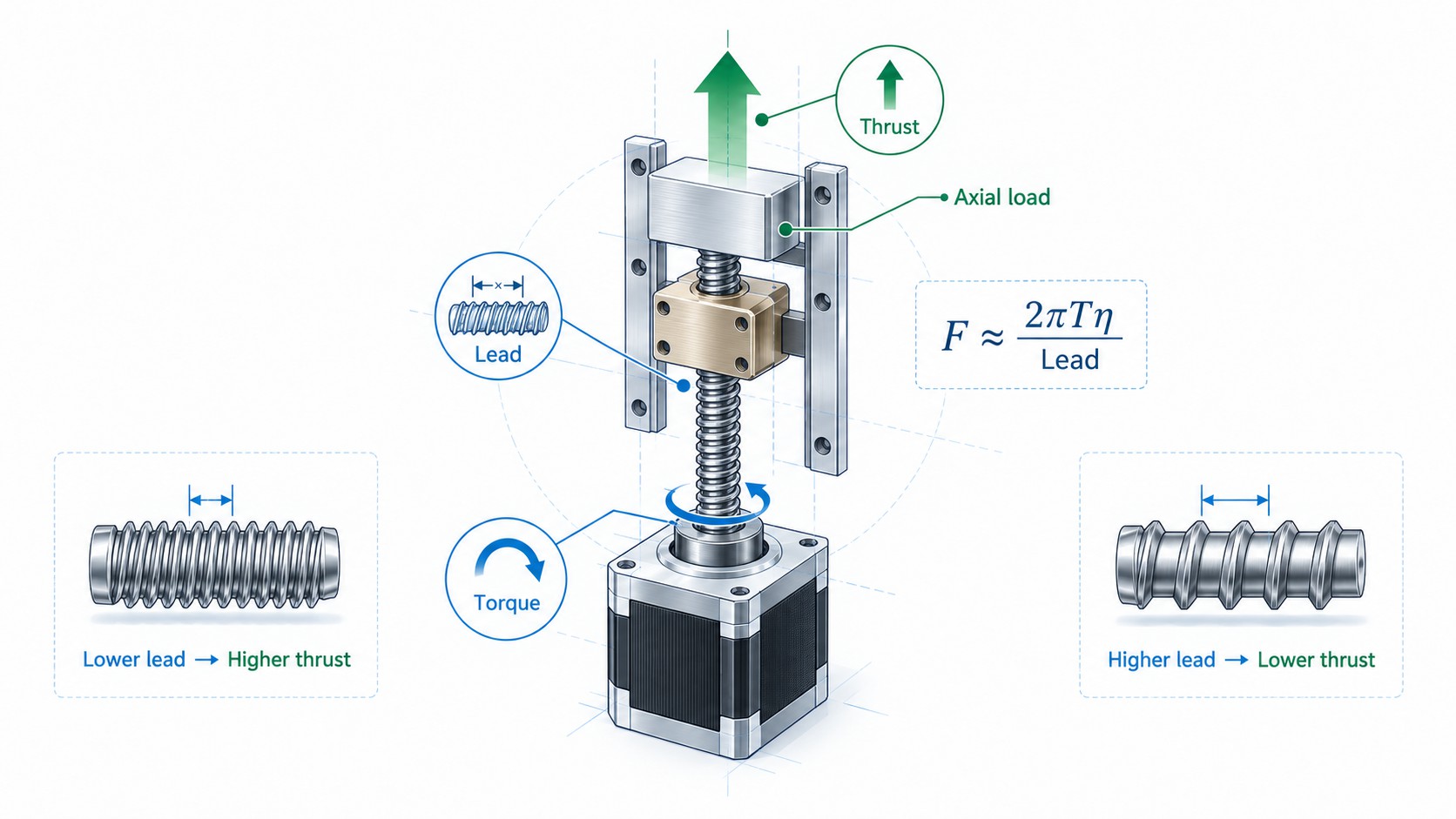
A screw converts motor torque into axial force. A useful first-order relationship is:
F = (2 × π × η × T) / L
where:
-
F = theoretical axial thrust, N;
-
η = screw efficiency as a decimal;
-
T = torque available at the screw, N·m;
-
L = screw lead, m/rev.
Rearranged to find required torque:
T = (F × L) / (2 × π × η)
Haydon Kerk publishes the same fundamental relationship in its and emphasizes that total motor torque must also include screw inertia, drag torque, bearing friction, other moving components and assembly misalignment.
Why Smaller Lead Usually Produces More Thrust
If torque and efficiency were identical, thrust is inversely proportional to lead.
For a normalized example using 0.10 N·m of shaft torque and assuming 100% ideal efficiency only to show the mechanical ratio:
| Lead | Ideal thrust per 0.10 N·m | Relative mechanical advantage |
|---|---|---|
| 2 mm | 314 N | 4.0× |
| 4 mm | 157 N | 2.0× |
| 8 mm | 78.5 N | 1.0× |
So a 2 mm lead theoretically produces four times the axial force of an 8 mm lead at the same shaft torque and the same efficiency.
Real systems are more complicated because efficiency is not constant. Lead angle, thread geometry, lubrication, nut material and preload change the efficiency. Thomson product data, for example, shows that different acetal anti-backlash lead screw combinations can range from roughly 29% efficiency for a 6 mm × 1 mm screw to over 80% for very high-lead designs. These are product-specific examples, not universal values, but they demonstrate why a thrust calculation should use the actual screw/nut data rather than a generic assumed efficiency.
Never Use Holding Torque as the Final Thrust Input
One of the most common mistakes in linear actuator sizing is to calculate thrust from the motor’s holding torque and treat the result as available thrust at operating speed.
Holding torque is measured at zero speed. A stepper operating at hundreds or thousands of rpm will normally produce less torque. The correct calculation uses the available dynamic torque at the required rpm, based on the actual motor, driver current, driver voltage and winding connection.
If an application requires 80 mm/s and uses an 8 mm lead, the motor speed is 600 rpm. The thrust check must therefore use the motor’s available torque at approximately 600 rpm, not its static holding torque.
This is also why driver voltage matters. A higher appropriate bus voltage can improve current rise in an inductive stepper winding and preserve more torque at speed, provided the motor and driver remain within their limits. The complete electrical selection process is covered in FRANK HU MOTOR’s .
Include All Axial Forces
For a horizontal axis, a practical force model is:
F_required = F_process + F_friction + m × a
For a vertical upward acceleration:
F_required = F_process + F_friction + m × g + m × a
For vertical motion, gravity can be the largest continuous load. A 10 kg payload contributes approximately 98.1 N from gravity before friction, process force and acceleration are added.
When a vertical axis can back-drive, a brake, counterbalance, self-locking screw geometry or other holding method may also be required for safety. Do not assume the stepper’s holding torque alone is an acceptable safety device.
Motor Speed, Screw Speed and Controller Pulse Rate
Once the lead is selected, the required motor speed follows directly:
Motor rpm = linear speed × 60 / lead
If linear speed is in mm/s and lead is in mm/rev, the units cancel correctly.
Example: 100 mm/s with an 8 mm lead:
rpm = 100 × 60 / 8 = 750 rpm
The controller must also generate enough step pulses.
For a 1.8° motor at 1/16 microstepping:
pulses/rev = 200 × 16 = 3,200
At 750 rpm:
pulse rate = 750 / 60 × 3,200 = 40,000 pulses/s
A controller with a low maximum pulse frequency may therefore limit speed even when the motor and screw can operate faster.
For high-speed systems, do not automatically increase microstepping to the largest number offered by the driver. High microstep settings can increase pulse-rate demand without delivering a proportional improvement in real positioning accuracy.
Long Stroke Design: Critical Speed Can Become the Limiting Factor
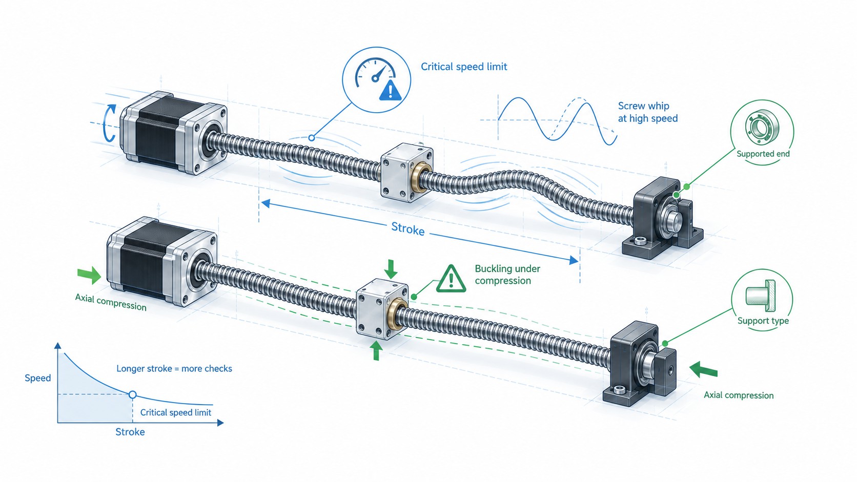
A rotating screw behaves like a slender rotating shaft. At a certain rpm, it approaches a natural bending frequency and can whip or resonate. This is the critical speed.
Critical speed becomes increasingly important as stroke and unsupported screw length increase.
Thomson gives the metric relationship:
n_c = C_s × 1.2 × 10^8 × d_r / L²
where:
-
n_c = calculated critical speed, rpm;
-
C_s = end-fixity factor;
-
d_r = screw root diameter, mm;
-
L = length between bearing supports, mm.
Thomson recommends a maximum safe operating speed of approximately:
n_safe = 0.8 × n_c
The supporting data and equations are published in Thomson’s and .
Critical-Speed End-Fixity Factors
| Screw support condition | Critical-speed factor C_s |
|---|---|
| One end fixed, one end free | 0.36 |
| Both ends supported | 1.00 |
| One end fixed, one end supported | 1.47 |
| Both ends fixed | 2.23 |
This table explains why support design can be as important as screw diameter.
Example: 6.5 mm Root Diameter, 500 mm Unsupported Length
Consider a generic screw with a 6.5 mm root diameter and 500 mm unsupported length. These are illustrative dimensions only; always use the actual root diameter from the selected screw.
| Support condition | Calculated critical speed | 80% recommended operating ceiling |
|---|---|---|
| Fixed-free | ~1,123 rpm | ~898 rpm |
| Supported-supported | ~3,120 rpm | ~2,496 rpm |
| Fixed-supported | ~4,586 rpm | ~3,669 rpm |
| Fixed-fixed | ~6,958 rpm | ~5,566 rpm |
The same physical screw changes from a safe-speed ceiling below 900 rpm to more than 5,500 rpm simply by changing end support conditions in the theoretical model.
Now connect the result back to lead selection. At the fixed-free safe speed of roughly 898 rpm:
-
2 mm lead corresponds to about 29.9 mm/s;
-
8 mm lead corresponds to about 119.7 mm/s.
This illustrates an important benefit of higher lead in long-stroke systems: a higher lead can achieve a target linear speed at a lower screw rpm, improving margin below critical speed.
However, higher lead also reduces mechanical advantage and may increase back-driving. The optimum lead is therefore a compromise, not simply “the fastest lead available.”
Ways to Improve Critical-Speed Margin
If the selected design is too close to critical speed, engineers can consider:
-
increasing screw root diameter;
-
reducing unsupported screw length;
-
improving end support from fixed-free to fixed-supported or fixed-fixed;
-
increasing lead so the required linear speed is achieved at lower rpm;
-
using a rotating-nut architecture in suitable applications; or
-
replacing the mechanism with a different actuator technology if very long stroke and very high speed must be combined.
Screw Buckling: The Other Long-Stroke Limit
Critical speed is mainly a rotational-speed problem. Buckling is mainly a compressive-load problem.
A long slender screw under compression can bend laterally even if the nut itself and motor can generate more axial force. This is especially important on vertical lifting axes, presses, clamps and any arrangement where the screw is pushed rather than kept in tension.
Thomson gives the metric critical buckling relationship:
F_c = C_s × 9.687 × 10^4 × d_r^4 / L²
and recommends a safe compression load using a factor of up to 0.8:
F_safe = 0.8 × F_c
The buckling end-fixity factors differ from the critical-speed factors.
| Screw support condition | Buckling factor C_s |
|---|---|
| One end fixed, one end free | 0.25 |
| Both ends supported | 1.00 |
| One end fixed, one end supported | 2.00 |
| Both ends fixed | 4.00 |
THK independently emphasizes the same design issue in its , stating that the screw shaft must be selected so it will not buckle under the maximum compressive axial load.
Buckling Example Using the Same 6.5 mm Root Diameter and 500 mm Length
| Support condition | Calculated critical buckling force | 80% illustrative safe load |
|---|---|---|
| Fixed-free | ~173 N | ~138 N |
| Supported-supported | ~692 N | ~553 N |
| Fixed-supported | ~1,383 N | ~1,107 N |
| Fixed-fixed | ~2,767 N | ~2,213 N |
This example shows why a long screw that appears strong enough by thread size can still fail a column-stability check when used in compression.
Design the Screw to Work in Tension When Possible
If the machine layout allows it, arranging the screw so that the dominant load places it in tension can greatly reduce buckling concerns. Thomson explicitly lists designing the screw to operate in tension as one of the options when a design fails compression-load criteria.
Do Not Ignore Bearings and Mounts
Even if the screw shaft passes its buckling calculation, the complete axis must also satisfy:
-
fixed-bearing axial load capacity;
-
support-bearing capacity;
-
nut static and dynamic load ratings;
-
bracket stiffness;
-
motor bearing limitations if axial load reaches the motor; and
-
structural alignment.
The motor should not automatically be used as the primary axial thrust bearing unless the motor design explicitly supports that loading condition.
Resolution, Repeatability and Accuracy Are Not the Same Specification
This distinction is fundamental to good linear stepper motor selection.
Resolution
Resolution is the smallest commanded increment according to the motor step angle, microstep setting and screw lead.
For a 1.8° motor:
full-step resolution = lead / 200
At 1/16 microstepping:
commanded microstep increment = lead / (200 × 16)
This is a command quantity, not a guarantee that the carriage moves by exactly that amount every time.
Repeatability
Repeatability describes how closely the mechanism returns to the same position under similar conditions. Backlash, friction, preload, temperature and load direction strongly affect repeatability.
As a manufacturer-specific benchmark, Thomson’s motorized lead screw literature lists typical positional repeatability of approximately 0.127 to 0.254 mm with a standard nut and less than 0.051 mm with an anti-backlash nut for the referenced product family. The same document lists standard screw lead accuracy of 250 µm per 300 mm and precision lead accuracy of 75 µm per 300 mm. These values should not be assumed for every lead screw, but they are useful examples of why screw and nut specifications matter as much as motor step size. See Thomson’s .
Absolute Positioning Accuracy
Absolute accuracy is the difference between commanded position and actual position across the axis travel. It can include error from:
-
screw lead accuracy;
-
pitch variation;
-
nut backlash;
-
motor step-angle error;
-
microstep nonlinearity;
-
elastic deformation of screw, nut, bearings and brackets;
-
guide straightness and angular error;
-
thermal expansion;
-
assembly misalignment; and
-
calibration or controller compensation.
THK identifies lead-angle accuracy, axial clearance and axial rigidity as key contributors to ball screw positioning accuracy, and also notes the effect of temperature rise. Its recommends measures such as reducing heat generation and, in high-accuracy systems, compensating for expected thermal growth.
Backlash Matters Most When Direction Reverses
Backlash is mechanical lost motion when the direction of travel reverses. A system that always approaches a position from the same direction can sometimes tolerate more backlash than a bidirectional positioning axis.
For a bidirectional CNC, inspection stage or robot mechanism, backlash may dominate the real positioning error even when the theoretical motor resolution is very fine.
Microstepping Does Not Automatically Create Micron Accuracy
Suppose a 2 mm lead actuator is set to 1/32 microstepping:
2 mm / (200 × 32) = 0.0003125 mm = 0.3125 µm commanded increment
It would be incorrect to advertise that axis as a “0.3 µm accuracy actuator” based only on that calculation. The screw lead error over 300 mm may be tens or hundreds of micrometers, the nut may have measurable clearance, and motor electromagnetic nonlinearity under load can cause microstep position error.
Use microstepping primarily for smoothness, vibration reduction, noise reduction and command granularity unless the complete electromechanical system has been characterized for true positioning accuracy.
Backlash Control: Standard Nut, Anti-Backlash Nut or Preloaded Ball Screw?
There are several ways to improve reversal accuracy.
Standard Polymer Nut
A standard polymer nut is economical, quiet and can operate with low friction. It is suitable for applications where moderate backlash is acceptable or where motion is mostly in one direction.
Anti-Backlash Lead Screw Nut
An anti-backlash nut uses a spring, split-nut arrangement, compensating geometry or another preload mechanism to remove axial clearance between the nut and screw.
The benefits are:
-
better bidirectional repeatability;
-
reduced lost motion;
-
easier control of small reversals; and
-
wear compensation in some designs.
The cost is additional drag torque, preload force and wear. Haydon Kerk notes that anti-backlash assemblies add drag torque, and Thomson’s ActiveCAM anti-backlash products are specifically designed to compensate for wear while maintaining zero axial backlash in their rated application.
Preloaded Ball Screw
A ball screw can be preloaded to reduce or eliminate axial clearance while increasing axial rigidity. THK states that preload is generally used for high-accuracy positioning and that it increases nut rigidity. Its published precision ball screw clearance categories include options from zero-or-less clearance to defined positive clearances depending on the product and grade. See THK’s .
Preload is not free. It increases internal load, starting torque, running torque and heat, and it must be included in life calculations.
Nut Material: POM, Other Engineering Polymers, Bronze and Ball Nuts
Nut material affects friction, noise, lubrication, wear, load capacity, temperature capability and environmental suitability.
POM / Acetal
POM, also called acetal or polyacetal, is widely used in compact lead screw actuators because it can provide low friction, low noise and good manufacturability. FRANK HU MOTOR uses POM nuts in several external linear stepper configurations.
Haydon Kerk states that its standard lead screw nuts are commonly made from self-lubricating polyacetal and that other materials such as PEEK can be used for special environments. The company also notes that self-lubricating polymer nuts can operate without external grease in many designs. See .
High-Performance Polymers
PEEK and other engineered polymers may be selected for elevated temperature, vacuum, chemical resistance or special medical and clean applications. Material choice should be based on pressure-velocity limits, temperature, environment and desired life rather than simply using the same nut material for every machine.
Bronze or Metallic Nuts
Metallic nuts can offer high load capacity and temperature capability, but they may require lubrication and can generate more friction or noise depending on the material combination and thread design.
Haydon Kerk’s discussion of lead screw noise and vibration notes that engineered thermoplastic nuts can have lower friction than typical metallic bronze combinations in certain designs, with polyacetal-based examples producing very low friction and quiet operation. Again, the exact value depends on the specific screw coating and nut system.
Ball Screw Nut
A ball screw nut uses rolling elements rather than sliding thread contact. This gives high efficiency and makes ball screws attractive for high-speed, high-duty-cycle and high-rigidity applications. The trade-offs are higher cost, more complex lubrication and contamination control, and possible preload-related heat.
Lead Screw Life and Ball Screw Life Are Evaluated Differently
There is no single universal “life formula” for every lead screw and polymer nut combination. Sliding lead screw life depends on:
-
nut material;
-
contact pressure;
-
sliding speed;
-
duty cycle;
-
lubrication or coating;
-
contamination;
-
alignment;
-
temperature; and
-
reversal frequency.
For this reason, suppliers often publish test-based travel-life or pressure-velocity limits for a specific screw/nut family. Thomson, for example, lists a typical linear travel life of 125 km for one motorized lead screw family under its defined conditions. That figure is useful only when interpreted within the manufacturer’s product assumptions.
Ball screw life is more standardized because fatigue life can be related to dynamic load rating. THK gives the nominal ball screw life relationship:
L10 = (C_a / F_a)³ × 10⁶ revolutions
where:
-
L10 = nominal life in revolutions;
-
C_a = basic dynamic load rating;
-
F_a = applied axial load.
THK defines nominal life as the total revolutions that 90% of a group of identical ball screws can achieve without fatigue flaking under the specified conditions. It also provides load factors for vibration and impact. See THK’s .
This cube relationship is significant. If applied load rises substantially, calculated fatigue life can fall very quickly. Oversizing a ball screw only by static strength may therefore result in inadequate service life.
Lead Screw vs Ball Screw Stepper Motor: Which Should You Buy?
The answer depends on the machine rather than on a universal ranking.
| Requirement | Lead screw stepper | Ball screw stepper |
|---|---|---|
| Purchase cost | Usually lower | Usually higher |
| Efficiency | Moderate, strongly dependent on lead and nut | High |
| Self-locking tendency | Possible with low lead / low efficiency | Usually back-drivable |
| Noise | Very low with suitable polymer nut | Low, but recirculating balls may produce characteristic sound |
| Backlash control | Standard or anti-backlash nut | Preload / precision nut options |
| High duty cycle | Application dependent | Generally better suited |
| High thrust at low speed | Strong mechanical advantage with low lead | Excellent, with high efficiency |
| Very high speed | Critical-speed limited; friction may generate heat | Strong option when properly sized |
| Contamination tolerance | Polymer nut systems can be forgiving | Requires good contamination and lubrication control |
| Precision positioning | Good with precision screw + anti-backlash design | Strongest option for high rigidity and low backlash |
| Maintenance | Can be low with self-lubricating polymer nut | Lubrication normally important |
A low-cost desktop mechanism moving occasionally may be better served by a trapezoidal lead screw. A production machine running thousands of cycles per day may justify the cost of a ball screw because efficiency, thermal behavior and life become more important than initial purchase price.
For applications where stepper technology itself is being compared with a servo, see FRANK HU MOTOR’s .
Lead Selection for High Speed, High Thrust and High Accuracy
The following rules are useful for preliminary screening.
Choose a Smaller Lead When
-
high axial force is required at low to moderate speed;
-
fine full-step resolution is valuable;
-
self-locking tendency is useful;
-
the required linear speed is low enough that motor rpm remains reasonable; or
-
controller pulse rate and motor speed are not limiting.
Typical examples include focusing mechanisms, dosing systems, clamps, valves and compact precision stages.
Choose a Larger Lead When
-
higher linear speed is required;
-
a lower motor rpm is needed to preserve stepper torque;
-
long stroke makes critical screw speed a concern;
-
cycle time is more important than extremely fine mechanical increment; or
-
the application can tolerate lower mechanical advantage or has enough motor torque.
Typical examples include packaging adjustments, pick-and-place travel, high-speed positioning and longer-stroke automation axes.
Do Not Choose Lead from Resolution Alone
If a designer chooses 1 mm lead because 0.005 mm/full-step resolution looks attractive, but the machine requires 100 mm/s, the screw would need 6,000 rpm. That speed may be outside the practical torque range of the stepper and may exceed the screw’s safe critical speed.
An 8 mm lead would require only 750 rpm for the same 100 mm/s linear speed. Even though its theoretical full-step increment is coarser, the complete axis may perform better.
A Practical Linear Stepper Motor Selection Workflow
The following process can be used for OEM inquiries and internal engineering reviews.
1. Define the Motion Profile
Record:
-
stroke;
-
maximum and continuous speed;
-
acceleration and deceleration time;
-
dwell time;
-
cycles per minute;
-
expected duty cycle; and
-
emergency-stop behavior.
Do not size from maximum speed alone. Acceleration can produce the peak force and peak torque.
2. Calculate Maximum Axial Force
For a horizontal axis, add process load, friction and inertial force.
For a vertical axis, include gravity.
Then add a realistic engineering margin for load variation, friction changes, wear and manufacturing tolerance.
3. Shortlist Candidate Leads
For each lead, calculate required motor rpm:
rpm = speed × 60 / lead
Reject combinations that require unrealistic motor speed or controller pulse frequency.
4. Calculate Required Screw Torque
Use:
T = F × L / (2π × η)
Then add:
-
nut drag torque;
-
screw acceleration torque;
-
rotor and reflected inertia torque;
-
bearing friction; and
-
margin for misalignment and process variation.
5. Check the Motor Torque-Speed Curve
The selected motor must provide enough dynamic torque at every important point in the motion profile.
Do not compare required running torque only with holding torque.
When deciding between NEMA 17, NEMA 23, NEMA 34 and other frames, remember that the NEMA number defines the mounting face, not guaranteed torque or performance. FRANK HU MOTOR’s explains this in detail.
6. Check Driver and Supply Voltage
Confirm:
-
phase current;
-
driver current setting;
-
supply voltage;
-
inductance;
-
desired microstep ratio;
-
controller pulse rate; and
-
thermal conditions.
A mechanically correct actuator can still underperform if the driver cannot maintain winding current at speed.
7. Check Critical Screw Speed
Use actual screw root diameter, unsupported length and support condition. Maintain an appropriate margin below critical speed; Thomson’s published guideline uses 80% as a maximum safe factor for its calculations.
8. Check Buckling and Axial Load
If the screw operates in compression, verify column buckling. Also check nut load rating, support-bearing capacity and mounting structure.
9. Define Accuracy and Backlash Requirements
Specify separately:
-
command resolution;
-
bidirectional repeatability;
-
backlash;
-
absolute travel accuracy; and
-
minimum practical move.
This prevents purchasing decisions based on an impressive but misleading microstep number.
10. Choose Nut and Screw Technology
Decide whether the application needs:
-
standard POM/acetal nut;
-
anti-backlash polymer nut;
-
special high-temperature or vacuum polymer;
-
bronze nut;
-
rolled ball screw; or
-
precision/preloaded ball screw.
11. Decide Open Loop or Closed Loop
If occasional step loss would be unacceptable, load variation is large or the motion is aggressive, consider encoder feedback.
12. Validate Thermal and Life Requirements
For continuous-duty systems, verify motor winding temperature, nut temperature, lubrication, expected wear, ball screw L10 life where applicable and environmental contamination.
Worked Engineering Example: Selecting Lead for a 100 mm/s Axis
Assume an automation axis requires:
-
300 mm stroke;
-
100 mm/s maximum speed;
-
moderate horizontal load;
-
bidirectional positioning;
-
target repeatability better than 0.05 mm; and
-
a NEMA 17 or compact NEMA 23 envelope.
We will compare 2 mm, 4 mm and 8 mm leads.
Required Motor Speed
| Lead | Required rpm at 100 mm/s | Full-step increment with 1.8° motor |
|---|---|---|
| 2 mm | 3,000 rpm | 0.010 mm |
| 4 mm | 1,500 rpm | 0.020 mm |
| 8 mm | 750 rpm | 0.040 mm |
A 2 mm lead gives excellent theoretical full-step increment, but 3,000 rpm may be a poor operating point for a conventional NEMA 17 stepper depending on winding, voltage and required torque. It may also create critical-speed problems in a long rotating screw.
The 8 mm lead requires only 750 rpm. Its 0.04 mm full-step increment is already close to the target repeatability, so an anti-backlash nut, controlled approach direction, closed-loop architecture or ball screw may be needed depending on the final accuracy requirement.
The 4 mm lead is a middle solution: 1,500 rpm and 0.02 mm/full step.
The correct answer cannot be chosen from this table alone. The engineer must next compare dynamic motor torque, calculated thrust, screw critical speed, backlash and life.
This is the central lesson of linear actuator lead selection: lead is a system ratio connecting motor speed, mechanical advantage and positioning increment.
When a Closed-Loop Linear Stepper Is Worth the Extra Cost
Closed-loop stepper systems are not necessary for every axis. Open-loop steppers remain attractive because they are simple, robust and economical when properly sized.
Closed loop becomes more valuable when:
-
the load is uncertain or changes during the process;
-
the axis sees impacts or intermittent jams;
-
acceleration must be aggressive;
-
operating speed is near the edge of the motor’s open-loop torque capability;
-
the machine must detect motion errors rather than silently continue;
-
higher utilization of the motor’s torque envelope is commercially valuable; or
-
downtime is more expensive than the added encoder and driver cost.
However, an encoder mounted on the motor does not directly measure nut-to-carriage backlash, screw lead error or structural deflection. If the application requires true load-position verification, consider a linear encoder or another feedback device at the moving load.
Selection by Application
| Application | Typical priority | Recommended direction |
|---|---|---|
| 3D printer Z axis | Low cost, holding force, moderate speed | Lead screw stepper, moderate/low lead |
| Desktop CNC Z axis | Thrust, stiffness, low backlash | Low-lead lead screw or ball screw; consider anti-backlash |
| CNC X/Y axis | Speed, stiffness, repeatability | Ball screw stepper or servo depending speed/size |
| Optical focusing | Fine increment, low noise | Small lead, precision nut, NEMA 8/11/14 |
| Medical/lab pump | Repeatability, compactness, cleanliness | Captive or non-captive linear stepper, selected polymer nut |
| Pick-and-place | Speed and acceleration | Higher lead, closed loop or servo if dynamics are aggressive |
| Valve/clamp | Thrust and holding | Low lead, captive actuator if stroke is short |
| Packaging adjustment | Fast repositioning, low maintenance | External linear stepper, moderate/high lead |
| Long-stroke automation | Speed plus critical-speed margin | Larger lead, larger screw diameter, improved end support |
| High-duty production axis | Life, efficiency, heat | Ball screw stepper or servo system |
Procurement Checklist for OEM and Custom Linear Stepper Motors
When requesting a quote from FRANK HU MOTOR or another motion supplier, include enough information for the supplier to validate the design rather than simply return a price for a frame size.
A useful RFQ should contain:
-
Motor frame size or maximum envelope — NEMA 8, 11, 14, 17, 23, 34 or custom.
-
Actuator architecture — captive, non-captive, external, ball screw, closed loop or complete module.
-
Screw diameter and lead — or provide speed/thrust requirements so the supplier can recommend them.
-
Required screw length or stroke — distinguish total screw length from useful travel.
-
Maximum axial load — include process load and whether the axis is vertical.
-
Maximum linear speed — preferably with acceleration time.
-
Duty cycle and cycles per hour/day.
-
Required repeatability, backlash and absolute accuracy — specify each separately.
-
Nut material and preload requirement — standard POM, anti-backlash, special polymer, ball nut, etc.
-
Motor current, voltage and preferred driver — if already defined.
-
Encoder requirement — PPR/CPR, output type and connector if closed loop is needed.
-
Shaft/screw end machining — bearing seats, flats, threads, couplings and custom lengths.
-
Environmental requirements — temperature, dust, cleanroom, vacuum, humidity or chemical exposure.
-
Cable length and connector type.
-
Annual volume and prototype quantity — important for OEM/ODM optimization.
FRANK HU MOTOR supports custom shafts, windings and OEM/ODM motion-control configurations, so providing this engineering information early helps avoid a catalog part that is inexpensive initially but poorly matched to the machine.
Common Linear Stepper Selection Mistakes
Choosing Only by NEMA Size
NEMA 17 defines the mounting frame, not the linear thrust, high-speed torque, screw lead or accuracy. Two NEMA 17 actuators can have completely different dynamic behavior.
Calculating Thrust from Holding Torque
Holding torque is not the same as available running torque. Always use dynamic torque at the actual operating rpm.
Selecting the Smallest Lead for “Maximum Accuracy”
A very small lead may force the motor to run at impractically high rpm. The axis can then lose torque, become noisy or exceed critical screw speed.
Selecting the Largest Lead for “Maximum Speed”
A large lead reduces mechanical advantage. The motor may not produce enough thrust, especially during acceleration or vertical lifting.
Treating Microstep Size as Mechanical Accuracy
Microstepping creates finer command increments but does not remove screw lead error, backlash, compliance or motor step-angle error.
Ignoring Screw Support Conditions
The same screw diameter and length can have very different critical speed and buckling limits depending on whether the ends are fixed, supported or free.
Ignoring Vertical Back-Driving
High-efficiency or high-lead screws can back-drive under gravity. A vertical axis may require a brake or counterbalance.
Specifying Only Stroke, Not Total Screw Length
Bearing supports, nut length, end machining and overtravel all affect the required screw length. “300 mm stroke” is not automatically the same as “300 mm screw.”
Ignoring Alignment
Misalignment increases drag torque, heat and wear. A precision screw installed in a flexible or misaligned bracket can perform worse than a less expensive screw installed correctly.
Frequently Asked Questions
What lead is best for a NEMA 17 lead screw stepper motor?
There is no universal best lead. A 2 mm lead favors mechanical advantage and finer full-step increment, while an 8 mm lead provides four times the linear travel per revolution. The correct choice depends on required speed, thrust, motor torque at the required rpm, screw critical speed and positioning requirements.
How do I calculate linear speed from lead?
Use:
linear speed = lead × rpm / 60
For an 8 mm lead at 600 rpm:
8 × 600 / 60 = 80 mm/s
How do I calculate lead screw thrust from stepper torque?
Use the first-order relationship:
F = 2πηT / L
Use the motor’s dynamic torque at operating speed, not holding torque, and include real screw efficiency plus drag and acceleration torque.
Is a 2 mm lead always more accurate than an 8 mm lead?
It has four times finer theoretical full-step linear increment with the same 1.8° motor, but absolute accuracy depends on screw lead accuracy, backlash, nut stiffness, motor step-angle accuracy, thermal expansion, guide error and calibration. A well-built 8 mm lead ball screw axis can be more accurate than a low-cost 2 mm lead screw axis.
Does 1/16 microstepping give 16 times better positioning accuracy?
No. It gives 16 times finer electrical command increments. Real mechanical accuracy does not automatically improve by the same factor.
When should I use an anti-backlash nut?
Use one when direction reversals matter and the standard nut’s axial clearance would create unacceptable lost motion. Remember that anti-backlash preload adds drag torque and can affect wear and efficiency.
When should I choose a ball screw stepper motor?
Choose a ball screw when higher efficiency, high duty cycle, low backlash, high axial rigidity or longer fatigue life are more important than minimum purchase price. Ball screws are also attractive when the motor would otherwise need excessive torque to overcome sliding friction.
What limits the speed of a long lead screw?
Three common limits are motor torque at rpm, screw critical speed and nut/screw operating limits. The longest rotating screw is often limited by critical speed before the motor reaches its theoretical maximum rpm.
What causes lead screw buckling?
Buckling occurs when a long slender screw is loaded in compression beyond its elastic stability limit. Screw root diameter, unsupported length and end support condition strongly affect the allowable load.
Is a non-captive actuator better than an external actuator?
Neither is universally better. A non-captive actuator is compact because the screw passes through the motor, but the screw or load must be prevented from rotating. An external actuator is mechanically intuitive and easy to connect to a carriage, but the rotating screw must be checked for critical speed.
Does a closed-loop stepper remove backlash?
No. A motor-mounted encoder monitors motor position. Mechanical backlash between screw and nut can remain. If true load position must be measured, a linear encoder at the load may be required.
How much safety factor should I use?
There is no single factor for every part of the system. For screw critical speed and buckling, Thomson’s published engineering method uses a maximum operating factor of 0.8 relative to the calculated critical value. For ball screw static loading, THK publishes lower-limit static safety factor guidance of 2 without vibration/impact and 5 with vibration/impact for applicable models. Motor torque margin must be chosen according to load uncertainty, acceleration, duty cycle and consequences of missed steps.
How do I choose between NEMA 17 and NEMA 23 for a linear actuator?
First calculate required dynamic torque and rpm from the linear load, lead and motion profile. Then compare the required torque with actual speed-torque curves for candidate motors and drivers. NEMA 23 usually provides more torque capacity and thermal mass, but it is larger and has higher rotor inertia. The smallest motor with adequate dynamic and thermal margin is normally the better engineering choice.
A Buyer’s Decision Matrix
For fast preliminary selection, use the following matrix before requesting a detailed engineering review.
| If your highest priority is... | Start by evaluating... | Then verify... |
|---|---|---|
| Maximum thrust | Smaller lead, larger motor | Dynamic torque, buckling, nut load |
| Maximum linear speed | Larger lead | Motor torque, critical speed, back-driving |
| Fine commanded increment | Smaller lead | True screw accuracy, backlash, microstep behavior |
| Bidirectional repeatability | Anti-backlash nut or preloaded ball screw | Drag torque, wear, heat |
| Long stroke | Larger screw diameter and better end support | Critical speed and buckling |
| High duty cycle | Ball screw or optimized polymer nut | Life, lubrication, temperature |
| Low noise | Polymer lead screw nut | Load, temperature, life |
| Low purchase cost | Standard lead screw stepper | Long-term wear and cycle time |
| Error detection | Closed-loop stepper | Mechanical backlash remains |
| Highest machine-level precision | Precision/preloaded ball screw + direct feedback | Thermal growth, structure, calibration |
Final Selection Guidance
A lead screw stepper motor should be selected as an electromechanical system, not as a motor with a screw attached.
The screw lead determines the fundamental trade between linear speed, mechanical advantage and commanded resolution. The motor and driver determine how much torque remains available at the required rpm. Screw length, root diameter and end support determine whether critical speed or buckling becomes the limiting factor. The nut determines backlash, friction, noise and wear. Feedback determines whether motor position errors can be detected, but it does not automatically remove mechanical error.
For the NEMA 17 example in this guide, changing from a 2 mm lead to an 8 mm lead changes the full-step increment from 0.01 mm to 0.04 mm and increases linear speed at the same motor rpm by 4×. At 600 rpm, that means 20 mm/s versus 80 mm/s. At the same torque and efficiency, the smaller lead has four times the theoretical mechanical advantage, but the higher-lead design may preserve far more motor torque in a high-speed application because it needs much less rpm.
That is the core engineering decision: do not optimize one number in isolation.
When preparing a new design, define the load, speed, acceleration, stroke, orientation, accuracy, backlash, duty cycle and life target first. Then evaluate lead, motor frame, winding, driver voltage, screw diameter, end support, nut type and feedback together.
FRANK HU MOTOR supplies and customizes captive, non-captive, external, ball screw and closed-loop linear stepper solutions across compact NEMA 8/11/14 sizes through NEMA 17, NEMA 23 and larger industrial frames. For OEM/ODM projects, providing the complete motion profile and mechanical constraints allows the motor, lead screw, nut, encoder and driver to be optimized as one system rather than selected as unrelated components.
If you are still at the motor-sizing stage, continue with . If the motor is already chosen and you need to finalize the electronics, continue with