Choosing a motion system is rarely a simple “stepper or servo” decision anymore. For many CNC machines, packaging systems, laboratory instruments, 3D printers, dispensing platforms, indexing tables and automation axes, the practical shortlist contains three technologies:
-
an open-loop stepper motor;
-
a closed-loop stepper motor, also called a stepper servo or hybrid servo by some suppliers; and
-
a conventional AC servo motor and servo drive.
The closed-loop stepper has become important because it fills a real engineering and commercial gap. It keeps many of the familiar advantages of a stepper motor—high low-speed torque, simple pulse-and-direction control, strong holding behavior and relatively straightforward commissioning—while adding encoder feedback so that the drive can monitor position error and react when the rotor does not follow the command.
That does not mean a closed-loop stepper becomes a servo motor in every practical sense. It also does not mean that adding an encoder automatically improves the mechanical accuracy of a machine. A feedback device tells the drive what happened at the location where the feedback is measured; it cannot remove backlash, screw lead error, structural deflection, belt elasticity, coupling wind-up, bearing clearance or thermal expansion unless the control architecture measures and compensates those effects.
For purchasing teams, machine builders and automation engineers, the right question is therefore not “Which motor is best?” The useful question is:
Which system gives the required speed, torque, positioning reliability, accuracy, thermal behavior and diagnostic capability at the lowest justified total cost?
FRANK HU MOTOR supplies , , , motor drives and conventional servo solutions. This guide focuses on the engineering differences that matter when selecting among the three architectures rather than treating them as interchangeable product labels.
Fast Answer: Which One Should You Choose?
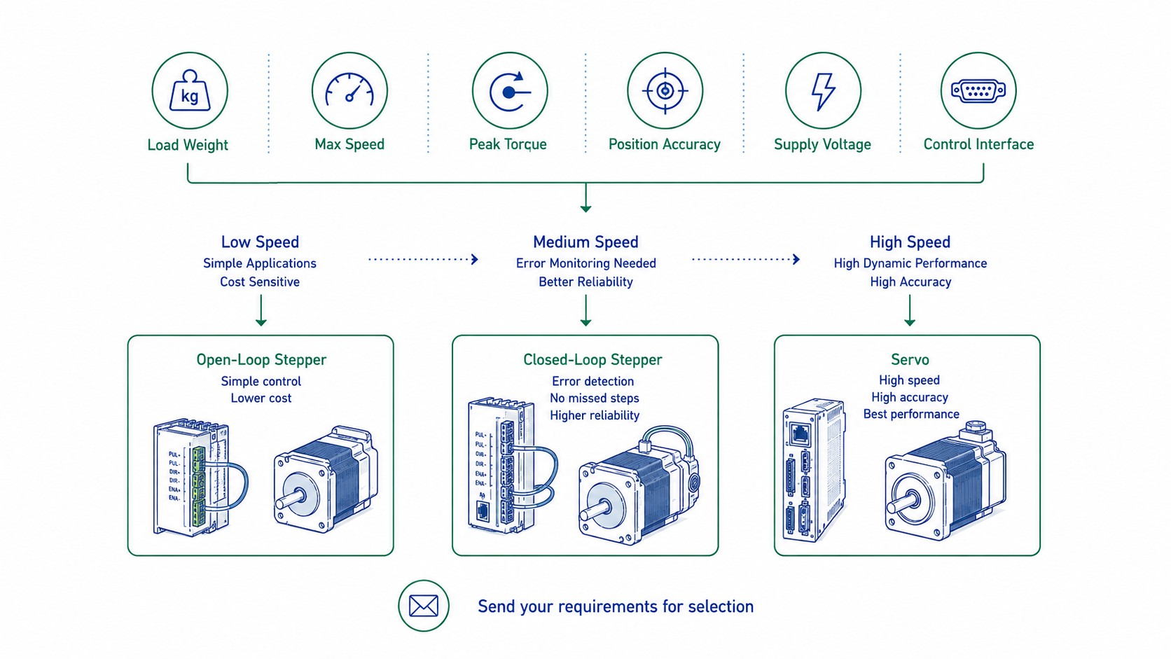
For a predictable, low-to-moderate-speed point-to-point axis, an open-loop stepper is often the most economical solution. If the machine cannot tolerate an unnoticed stall or skipped motion but still benefits from stepper simplicity, a closed-loop stepper is usually the next technology to evaluate. If the application requires a broad speed range, high acceleration, high continuous power, large transient torque, strong disturbance rejection or tightly coordinated contouring, a servo motor is normally the stronger choice.
The following table is a practical first filter. It is not a substitute for motor sizing or a torque-speed curve.
| Selection factor | Open-loop stepper | Closed-loop stepper | AC servo motor |
|---|---|---|---|
| Position feedback | None required | Encoder or position sensor | Encoder/resolver is fundamental to operation |
| Lost-motion detection | No inherent confirmation | Yes, within drive/encoder architecture | Yes, through following-error monitoring |
| Position correction | No closed-loop correction | Usually corrects rotor-position error; implementation varies | Continuous closed-loop correction |
| Low-speed torque | Excellent for frame size | Excellent, often with better current utilization | Strong, with rated and peak torque defined by system |
| Holding at zero speed | Natural stepper holding behavior | Natural stepper holding behavior plus feedback supervision | Active servo holding torque through feedback loop |
| High-speed torque | Falls as speed rises | Still limited by stepper electrical/mechanical design | Usually much stronger over a wider speed range |
| Heat at light load | Can remain high because current is commonly maintained | Often lower because current can be adapted to actual load | Efficient current-on-demand control |
| Gain/PID tuning | Normally none | Often none or simplified; some drives expose gains/filters | Auto-tuning is common, but servo gains and filters remain important |
| Disturbance rejection | Limited | Better than open loop | Best of the three when correctly sized and tuned |
| Complexity | Lowest | Medium | Highest |
| Typical project cost | Lowest | Medium | Highest, although the gap is application-dependent |
| Best fit | Predictable point-to-point motion | Moderate-speed axes requiring feedback and diagnostics | High dynamic performance and wide speed range |
A related FRANK HU MOTOR guide, , provides a broader two-technology comparison. The purpose of this article is to go deeper into the middle option: the closed-loop stepper.
What Actually Changes When You Add an Encoder to a Stepper Motor?
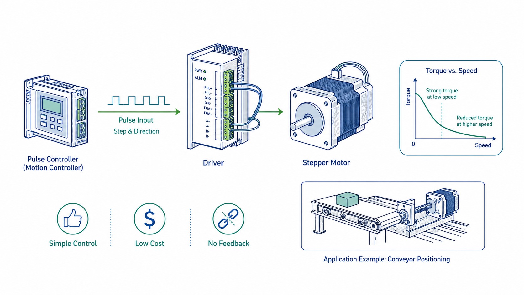
A conventional hybrid stepper motor is a synchronous device with many magnetic pole positions. A common two-phase 1.8° motor has 200 full-step positions per revolution. The drive energizes the windings in sequence and the controller assumes the rotor follows those electrical commands.
In an open-loop system, that assumption is the key simplification. The controller can count command pulses, but it does not inherently know whether the shaft actually moved the requested amount. If an external load exceeds the available torque, if acceleration is too aggressive, if the mechanism jams, or if resonance causes the rotor to fall out of synchronism, the controller may continue sending pulses even though actual position no longer matches commanded position.
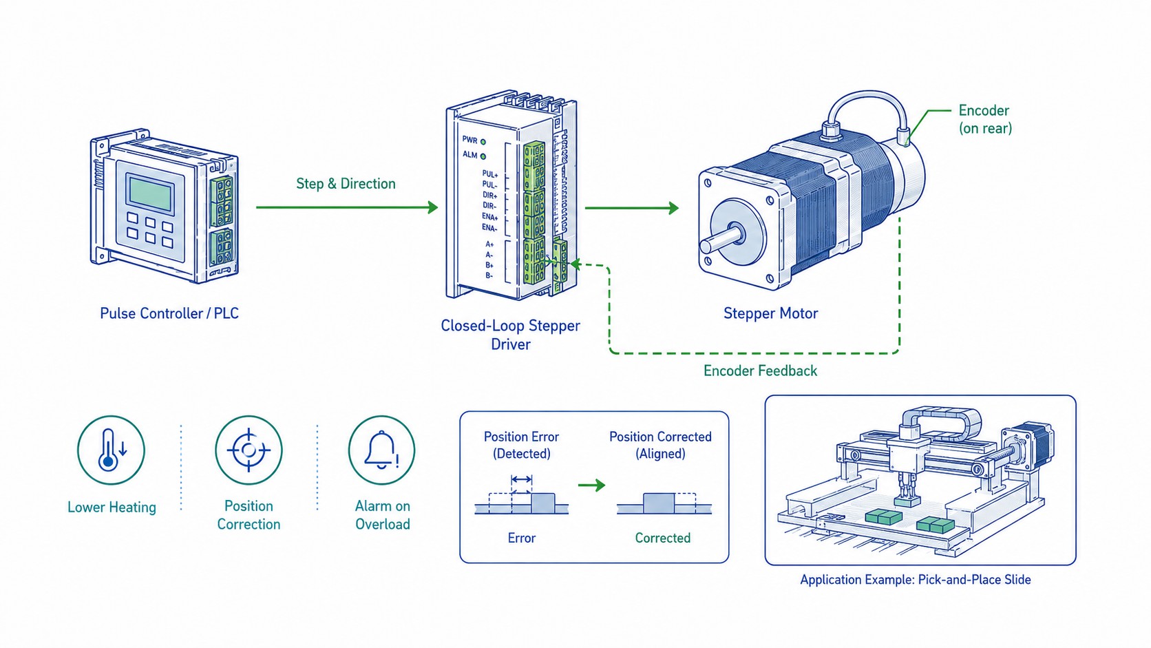
A closed-loop stepper adds a feedback sensor and a compatible drive. The feedback can be an incremental encoder, an absolute encoder or another rotor-position sensor. The drive can then compare commanded motion with measured motion.
Different manufacturers implement this feedback differently. Some systems operate primarily like a stepper and switch to corrective closed-loop behavior when the position deviation grows. Oriental Motor, for example, describes its as operating synchronously under normal conditions and switching into closed-loop correction when an overload causes position deviation. Other closed-loop stepper drives perform continuous servo-like position supervision and current adjustment.
This distinction matters commercially because the phrase “closed-loop stepper” does not define one universal control algorithm. Two products may both have encoders yet differ in:
-
how often feedback is sampled;
-
whether the loop continuously regulates rotor position or only intervenes beyond a deviation threshold;
-
whether the drive can command extra current temporarily;
-
whether it limits current at light load;
-
how following-error thresholds are configured;
-
whether the drive supports auto-tuning;
-
whether the feedback is motor-side or load-side;
-
whether the controller receives only an alarm output or actual position data;
-
whether the system can continue after a temporary overload; and
-
how a persistent error is handled.
For procurement, therefore, “motor with encoder” should never be treated as a complete specification. The motor, encoder and drive must be selected as a system.
Closed Loop Stepper vs Open Loop: The Most Important Difference Is Fault Visibility
The biggest practical weakness of a correctly sized open-loop stepper is not that it is inherently inaccurate. A good stepper system can repeat point-to-point moves very well within its designed torque and speed envelope. The bigger weakness is that it has no inherent proof that the commanded move actually occurred.
Imagine a pick-and-place axis commanded to move 80 mm. The motion controller sends the correct number of pulses. If the motor completes the move, the open-loop architecture works perfectly. If the axis is briefly blocked by a cable carrier, a contaminated guide or a collision, the pulse count in the controller can still look correct even though the mechanical position is wrong.
A closed-loop stepper makes that failure observable. It can compare command and feedback, attempt correction and, if the error exceeds the configured limit or persists too long, issue a position-following alarm. Leadshine’s closed-loop stepper products, for example, advertise position-error supervision and closed-loop operation, and its supports encoder-based closed-loop control, low-speed enhancement and configurable drive settings.
This is one reason closed-loop steppers are attractive for machines that already use step/direction control but need better production reliability. The architecture can often be upgraded without redesigning the entire motion-control platform.
Does a Closed-Loop Stepper Lose Steps?
The popular marketing answer is “no lost steps.” The more useful engineering answer is:
A closed-loop stepper can detect and correct a limited position error, but it cannot violate the motor’s torque-speed capability or mechanical limits.
If a temporary load disturbance slows the rotor, a properly designed closed-loop drive may increase corrective torque and bring the rotor back to the commanded position. If the disturbance disappears before the allowable following error is exceeded, the machine can continue normally.
If the axis is physically jammed, if the motor has insufficient torque at the commanded speed, if bus voltage is too low, if acceleration demands too much torque, or if the encoder signal is lost, the drive cannot magically force the axis through the obstruction. A correctly designed system should eventually alarm, disable motion, stop the cycle or ask the higher-level controller to execute a recovery sequence.
Oriental Motor states that its αSTEP system corrects position under overload but outputs an alarm if the overload condition continues. That is the correct mental model: feedback makes the failure detectable and sometimes recoverable; it does not make the system infinitely strong.
What Happens After a Position Error?
The exact sequence depends on the drive, but a typical closed-loop stepper fault path looks like this:
-
The controller commands a step position.
-
The encoder reports actual rotor position.
-
The drive calculates following error.
-
If error is small, the drive continues normally.
-
If error grows, the drive increases corrective action according to its control algorithm.
-
If the rotor catches up, normal operation continues.
-
If error exceeds a configured threshold, a fault or alarm output is generated.
-
The machine controller decides whether to stop, re-home, retract, reduce speed or request operator intervention.
This is why a machine builder should ask for the drive’s following-error limit, alarm behavior and reset logic, not merely whether the motor includes an encoder.
Does an Encoder Really Increase Mechanical Accuracy?
This is one of the most misunderstood questions in motion control.
An encoder can improve position knowledge and closed-loop behavior, but encoder resolution is not the same thing as machine accuracy.
Renishaw’s technical material on separates accuracy, repeatability, resolution and cyclic error because they describe different performance characteristics. A high number of encoder counts gives the controller finer measurement increments, but the physical measurement can still contain systematic and mechanical errors.
Consider a closed-loop stepper with a 1,000-line quadrature encoder. Leadshine lists products such as the with a 1,000-line encoder corresponding to 4,000 counts per revolution. The theoretical angular increment per count is:
\frac{360^\circ}{4000}=0.09^\circ
$$
Now compare that with a modern servo example. Panasonic lists the with a 23-bit encoder, or 8,388,608 counts per revolution. Its theoretical count increment is approximately:
\frac{360^\circ}{8,388,608}=0.0000429^\circ
$$
That is an enormous difference in feedback quantization. But it would be wrong to conclude that the servo-driven machine is automatically thousands of times more accurate.
Resolution, Repeatability and Accuracy Are Different
A useful way to separate the terms is:
-
Command resolution: the smallest command increment the controller can request.
-
Encoder resolution: the smallest feedback increment represented by the feedback interface.
-
Motor stopping accuracy: how close the motor shaft stops to the target under specified conditions.
-
Repeatability: how closely repeated moves return to the same position.
-
Absolute accuracy: how close the actual machine position is to the true intended physical coordinate.
The final machine accuracy also depends on the mechanical transmission.
For a linear axis using a 5 mm/revolution ball screw, a motor-angle error of 0.05° corresponds to a theoretical linear displacement of:
5\text{ mm}\times\frac{0.05}{360}=0.000694\text{ mm}=0.694\ \mu\text{m}
$$
That number looks excellent. Yet a real axis may have ball-screw lead error of several micrometers over travel, backlash or lost motion at reversals, thermal expansion, bearing compliance, coupling torsion, guideway error and frame deflection. Those errors can be much larger than the motor’s theoretical angular increment.
Motor-Side Encoder vs Load-Side Encoder
A standard closed-loop stepper normally places the encoder on the motor shaft. This tells the drive whether the motor rotor is in the commanded position. It does not directly measure the machine table, gripper, tool or carriage after the transmission.
If there is backlash between the motor and the load, the motor encoder cannot directly see the lost motion. If the ball screw expands as it warms, the motor encoder still reports the motor shaft accurately while the physical table coordinate shifts.
HEIDENHAIN explains why are used in high-accuracy machine tools: measuring the linear axis directly avoids error sources introduced by the mechanical transmission, including backlash, pitch error and ball-screw heating.
This leads to an important selection rule:
A motor encoder closes the loop around the motor. A load-side encoder closes the loop around more of the machine.
For ordinary CNC routers, automation modules and 3D printers, motor-side feedback is often sufficient. For metrology equipment, semiconductor stages, precision grinders, inspection systems and high-end machine tools, load-side feedback may be necessary to meet the actual accuracy specification.
Can a Closed-Loop Stepper Automatically Compensate Position Error?
Yes—but the meaning of “compensate” must be defined carefully.
A closed-loop stepper can generally compensate rotor-position deviation within its available torque and configured control limits. If the rotor lags because of a temporary load increase, the drive can adjust current and corrective torque. Some systems can regain the commanded position after the disturbance.
However, a motor-side encoder cannot automatically compensate an error it cannot observe.
It cannot directly correct:
-
gearbox backlash that occurs after the encoder;
-
coupling slip after the encoder;
-
ball-screw pitch error;
-
belt stretch that changes load position while motor position remains correct;
-
thermal expansion of the screw or machine structure;
-
tool deflection under cutting load;
-
fixture movement;
-
compliance in a robotic gearbox; or
-
mechanical lost motion between motor and working point.
A fully closed-loop architecture with a load-side linear or rotary encoder can correct more of these errors because it measures the output position directly. Oriental Motor’s work on is a good example of this distinction between motor-side and load-side feedback.
Correction Is Not the Same as Unlimited Recovery
Suppose a closed-loop NEMA 23 stepper has enough torque to follow the command at 600 rpm. If a brief 20% load spike makes the rotor lag, the drive may recover. If the same axis is commanded at a speed where available motor torque has already fallen below required load torque, position error will keep growing. Feedback tells the drive that the motor is failing; it does not create missing torque.
Therefore, closed-loop selection still requires the same fundamental sizing discipline described in FRANK HU MOTOR’s . The closed loop is a reliability feature and performance tool, not permission to ignore the torque-speed curve.
Why Closed-Loop Steppers Usually Run Cooler Than Open-Loop Steppers
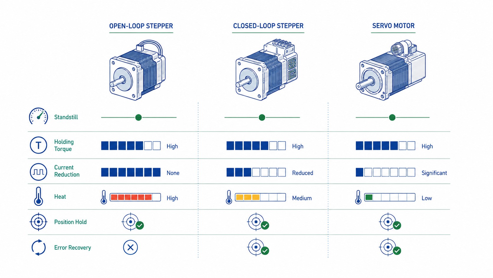
Traditional open-loop stepper drives are commonly configured to maintain a fixed phase-current setting based on the motor rating. This is one reason stepper motors can run surprisingly hot even when the mechanical load is light. The motor is being magnetically prepared to produce the required torque whether or not the load needs all of that torque at every instant.
Many open-loop drives include idle-current reduction, which lowers current after the axis stops. That helps, but during motion the drive still does not know the actual torque demand from position feedback.
A closed-loop stepper drive can use feedback to avoid supplying more current than necessary during light-load operation, depending on the control implementation. This reduces copper loss and therefore reduces heat generation.
Oriental Motor notes in its comparison of that conventional stepper current control is typically load-independent, while closed-loop feedback enables more efficient current utilization. Its is published with up to 40% lower power consumption than specified conventional models and reduced motor heat under the manufacturer’s test conditions.
These figures should not be generalized to every closed-loop stepper. The actual thermal improvement depends on:
-
motor winding resistance and inductance;
-
drive algorithm;
-
bus voltage;
-
phase-current limit;
-
acceleration profile;
-
duty cycle;
-
holding-current behavior;
-
mechanical load;
-
ambient temperature;
-
mounting plate thermal conductivity; and
-
enclosure airflow.
Why Heat Matters Beyond Touch Temperature
Lower heat is not merely a comfort or enclosure issue. Motor temperature affects:
-
winding resistance;
-
magnet and insulation life;
-
encoder electronics;
-
bearing grease life;
-
nearby sensors;
-
dimensional stability of precision mechanisms; and
-
the allowable duty cycle inside compact enclosures.
This is particularly important in laboratory automation, optical systems, 3D printers with enclosed heated chambers and compact CNC electronics cabinets. A cooler motor can reduce thermal drift and simplify mechanical packaging.
Why a Closed-Loop Stepper Cannot Completely Replace a Servo Motor
If feedback solves lost steps, why not replace every servo with a closed-loop stepper?
Because the fundamental motor designs remain different.
A hybrid stepper motor has many rotor and stator teeth and a high pole count. This construction gives strong low-speed torque, natural detent/holding behavior and excellent short-move responsiveness. But it also produces relatively high electrical frequency as mechanical speed rises. Winding inductance, back EMF and iron losses increasingly limit torque at higher rpm.
A permanent-magnet servo motor is designed around continuous closed-loop commutation over a much broader speed range. It generally has lower rotor inertia for a given performance class, strong transient overload capability and a flatter usable torque-speed envelope.
Kollmorgen summarizes this difference in its motion-control guidance: servo systems maintain useful torque over a much wider speed range, and its current engineering guidance notes that servo motors can reach speeds several times higher than many stepper applications. The exact crossover speed is not universal, but the principle is consistent: as sustained motor speed and dynamic power rise, the servo becomes increasingly attractive. See Kollmorgen’s discussion, .
Published Servo Data Shows the Different Operating Envelope
A real servo data point illustrates the concept. Panasonic’s 400 W MHMF042L1S1 lists:
-
1.27 N·m rated torque;
-
1.40 N·m continuous stall torque;
-
4.46 N·m momentary peak torque;
-
3,000 rpm rated speed;
-
6,500 rpm maximum speed; and
-
a 23-bit encoder with 8,388,608 counts per revolution.
This does not mean a 400 W servo is the correct replacement for a particular NEMA 23 or NEMA 34 closed-loop stepper. It shows that the servo’s specification is built around continuous power, rated speed, peak torque and high-speed operation, while a stepper is commonly selected from holding torque and a drive-specific torque-speed curve.
A Closed-Loop Stepper Still Has a Stepper Torque-Speed Curve
Adding an encoder does not remove winding inductance. It does not remove back EMF. It does not eliminate stepper iron losses. It does not convert the rotor into a low-inertia servo rotor.
A closed-loop drive can improve utilization of the motor’s available torque and prevent conservative “torque reserve” from being the only protection against lost steps, but the motor still has a physical torque-speed limit.
For this reason, the application should be evaluated in mechanical rpm, not only travel speed.
For a direct-driven ball screw:
n=\frac{v}{p}\times60
$$
where:
-
n = motor speed in rpm;
-
v = linear speed in mm/s; and
-
p = screw lead in mm/revolution.
For a 10 mm lead screw:
| Linear speed | Required motor speed |
|---|---|
| 100 mm/s | 600 rpm |
| 200 mm/s | 1,200 rpm |
| 300 mm/s | 1,800 rpm |
| 600 mm/s | 3,600 rpm |
At 100 mm/s, a stepper or closed-loop stepper may be very comfortable if the torque-speed curve provides adequate margin. At 600 mm/s, the same mechanical axis demands 3,600 rpm, where many hybrid stepper combinations are no longer competitive. A servo is much more likely to be the practical solution.
The correct crossover cannot be chosen from rpm alone. The required torque at that rpm, acceleration, reflected inertia, bus voltage and duty cycle must also be checked.
Low-Speed Holding: Closed-Loop Stepper vs Servo
Low-speed and zero-speed behavior is one of the strongest reasons to keep a stepper architecture.
A stepper motor naturally develops holding torque when energized. Because the rotor is magnetically aligned with discrete equilibrium positions, the system can hold a commanded stop without needing the same continuous position-loop behavior as a servo.
Oriental Motor specifically describes its closed-loop αSTEP systems as capable of holding the stop position without the “hunting” that can occur in a servo system. That characteristic can be valuable for low-rigidity belt drives, optical stages, dispensing equipment or inspection systems where tiny stop-position oscillations are undesirable.
A servo motor, by contrast, holds position by continuously measuring error and commanding current to reduce that error. A well-sized and well-tuned modern servo can hold extremely well, but the control loop is always part of the behavior. Poor tuning, mechanical compliance or excessive gain can create audible noise or small oscillation. Low gain can create softer holding and larger disturbance deflection.
Does This Mean a Stepper Is More Accurate at Standstill?
Not necessarily.
The stepper may be naturally stable and quiet at a fixed position, but its absolute shaft position is influenced by load torque and motor stiffness. An external torque can displace the rotor within the stable magnetic region even though the motor has not “lost a full step.”
A servo can actively counter external torque and can use extremely high-resolution feedback. Therefore, the better technology depends on whether the requirement is:
-
no visible hunting;
-
very high static stiffness;
-
minimum position error under disturbance;
-
low noise;
-
low power consumption; or
-
nanometer/micrometer-class load-side accuracy.
For a vertical axis, neither motor’s holding behavior should be treated as a personnel-safety brake. If loss of power can allow the load to fall, use a properly rated electromagnetic brake, counterbalance or mechanical safety device.
Speed Range and Inertia: The Two Variables That Often Decide the Winner
Many motor selections that look acceptable from torque alone fail because of speed or inertia.
Start With the Required Speed Range
A useful workflow is:
-
Convert machine speed into motor rpm.
-
Identify the highest rpm during normal production, homing and rapid traverse.
-
Determine required torque at each important speed point.
-
Check acceleration and deceleration torque.
-
Compare those points with the actual motor-drive torque-speed curve.
-
Add thermal and application margin.
For an open-loop or closed-loop stepper, the torque-speed curve must match the proposed driver current, supply voltage and winding connection. Holding torque is not enough.
For a servo, compare required continuous and peak torque against the servo’s rated and peak envelope, while also checking maximum speed, regenerative energy and thermal duty.
Then Calculate Reflected Inertia
Motor torque must accelerate both the motor rotor and the reflected load inertia:
T_a=J_{total}\alpha
$$
where:
-
Ta = acceleration torque;
-
Jtotal = total inertia reflected to the motor shaft; and
-
α = angular acceleration.
The load-to-motor inertia ratio is:
R_J=\frac{J_{load,reflected}}{J_{motor}}
$$
A high ratio means the motor is trying to control a load that stores much more rotational energy than the rotor itself. The axis becomes harder to accelerate, decelerate and stabilize.
There Is No Universal “10:1” Servo Rule
It is common to hear rules such as “servo inertia must be below 10:1.” That is too simplistic.
Manufacturer limits vary by motor size, rotor design, drive bandwidth, mechanism rigidity and tuning capability. Panasonic’s published MINAS A6 examples illustrate the variation:
| Example servo | Rated power / class | Published recommended inertia ratio | Rated / max speed |
|---|---|---|---|
| MHMF042L1S1 | 400 W, high inertia | 30:1 or less | 3,000 / 6,500 rpm |
| MHMF082L1D2M | 750 W-class family example | 20:1 or less | 3,000 / 6,000 rpm |
| MGMF242L1D8M | Larger high-inertia model | 10:1 or less | 1,500 / 3,000 rpm |
| MHMF304L1DAM | 3 kW model | 5:1 or less | 2,000 / 3,500 rpm |
The lesson is not that one ratio is “better.” The lesson is that inertia capability is model-specific.
Closed-loop steppers also have inertia limits, although they can be forgiving in short point-to-point moves because of their high pole count and low-speed torque. Oriental Motor publishes application guidance showing that closed-loop stepper systems can tolerate substantial load inertia in certain motion profiles. But the machine builder should use the selected system’s own data, not copy a universal ratio from another brand or frame size.
Gearboxes Can Change the Decision
A gearbox reduces reflected load inertia approximately by the square of the reduction ratio:
J_{reflected}=\frac{J_{load}}{i^2}
$$
where i is the speed-reduction ratio.
A 5:1 gearbox reduces reflected load inertia to 1/25 of the original load inertia, ignoring gearbox inertia. This can transform a difficult high-inertia axis into a manageable motor load.
However, a gearbox also introduces:
-
backlash;
-
torsional compliance;
-
efficiency loss;
-
additional inertia;
-
noise;
-
maintenance considerations; and
-
a higher motor speed for a given output speed.
FRANK HU MOTOR offers closed-loop motor and gearbox combinations such as a . In that product example, the published gearbox efficiency is 80% and no-load backlash is listed at up to 1.5°. Those values illustrate why gear reduction can improve torque and inertia matching while simultaneously limiting output-side accuracy.
Does a Closed-Loop Stepper Need PID Tuning?
Sometimes no; sometimes a little; sometimes effectively yes. The answer depends on the product architecture.
A conventional AC servo uses nested current, velocity and position loops. Servo drives therefore have control gains, filters and compensation parameters. Modern systems have made commissioning much easier through auto-tuning, inertia identification, adaptive notch filters and vibration suppression.
Panasonic’s , for example, includes automatic gain functions, adaptive notch filtering and a published 3.2 kHz frequency response. This is a good example of how modern servo technology reduces manual tuning effort without eliminating the underlying control-loop concepts.
Closed-loop stepper systems are different. Many are designed specifically to preserve the easy setup of a stepper. Oriental Motor states that its αSTEP systems can operate without conventional servo gain tuning. Leadshine’s CS-D507E also markets “no tuning” behavior while still exposing some current and gain-related settings for optimization.
Therefore, a practical answer is:
-
Open-loop stepper: generally no PID tuning.
-
Closed-loop stepper: often plug-and-run or auto-tuned; advanced products may expose stiffness, current or loop-gain parameters.
-
AC servo: increasingly easy to auto-tune, but tuning quality still matters when the mechanism is flexible, high-inertia or highly dynamic.
When Servo Tuning Still Becomes Important
Auto-tuning is not magic. Manual engineering may still be needed when:
-
a long belt or coupling creates torsional resonance;
-
the load inertia changes dramatically between cycles;
-
the axis has low mechanical rigidity;
-
settling time is extremely short;
-
machine vibration affects process quality;
-
two axes mechanically interact;
-
backlash creates nonlinear behavior;
-
a high-gain loop excites a frame resonance; or
-
the application needs exceptional disturbance rejection.
This is one reason closed-loop steppers are attractive for many retrofit and mid-performance applications. They can add feedback without requiring the machine builder to become a servo-control specialist.
Published Product Data: What the Numbers Do and Do Not Tell You
The following examples are not intended as direct substitutes for one another. They show how stepper and servo specifications are expressed differently and what a buyer should ask for.
| Example system/component | Key published data | What it tells you |
|---|---|---|
| FRANK HU MOTOR / Leadshine 57CME23 closed-loop NEMA 23 | 2.3 N·m holding torque, 5.0 A, 24–72 VDC system range, 1000 PPR encoder | Strong low-speed holding class, encoder-equipped stepper architecture; still requires torque-speed curve for running point |
| FRANK HU MOTOR / Leadshine 86CME45 closed-loop NEMA 34 | 4.6 N·m holding torque, 6.0 A, 24–110 VDC, 1000 PPR encoder | Higher holding torque for heavier axes; bus voltage and drive selection matter for speed |
| Leadshine CS-M22321-L | 2.1 N·m holding torque, 5 A, 1000-line / 4000-count encoder | Demonstrates typical closed-loop stepper feedback granularity and NEMA 23 class |
| Panasonic MHMF042L1S1 servo | 400 W, 1.27 N·m rated, 4.46 N·m peak, 3000 rpm rated, 6500 rpm max, 23-bit encoder | Servo is specified by continuous power, rated speed, peak torque and high-resolution feedback |
FRANK HU MOTOR product references: and .
Why Holding Torque Cannot Be Compared Directly With Servo Peak Torque
A 4.6 N·m stepper holding-torque number and a 4.46 N·m servo peak-torque number may look nearly equal, but they describe different conditions.
Holding torque is a zero-speed static characteristic. Servo peak torque is a short-duration overload capability within thermal and drive-current constraints. For motion selection, the buyer needs the actual torque available at the operating speed and duty cycle.
The correct comparison is therefore a motion profile over time:
-
acceleration torque;
-
running torque;
-
deceleration/regeneration;
-
dwell/holding requirement;
-
peak duration;
-
cycle frequency; and
-
worst-case ambient temperature.
Open-Loop Stepper: Where the Simple System Still Wins
Closed loop is valuable, but it is not automatically worth paying for.
An open-loop stepper remains a strong commercial choice when the mechanical load is predictable and the motor is sized with comfortable dynamic margin.
Typical examples include:
-
label dispensers;
-
small indexing tables;
-
light-duty Cartesian robots;
-
desktop CNC engravers;
-
3D printer X/Y axes;
-
camera sliders;
-
syringe pumps;
-
valve actuators;
-
low-cost pick-and-place feeders; and
-
laboratory mechanisms with periodic homing.
The advantages are straightforward:
-
fewer components;
-
no encoder cable;
-
lower purchase cost;
-
simple replacement;
-
no feedback setup;
-
easy pulse/direction integration; and
-
strong low-speed torque.
If the machine can safely home after a fault and the cost of an occasional position error is low, open loop may still be the best value.
When Open Loop Becomes a False Economy
The economics change when an undetected missed move causes:
-
scrapped parts;
-
a crashed tool;
-
a dispensing defect;
-
misaligned packaging;
-
a damaged probe;
-
a production stoppage that is difficult to diagnose; or
-
repeated service calls for “intermittent” positioning problems.
In those situations, the extra cost of encoder feedback can be recovered quickly through better diagnostics and reduced production risk.
Closed-Loop Stepper: The Practical Middle Ground
Closed-loop stepper systems are particularly attractive when a machine builder wants three things simultaneously:
-
stepper-like low-speed behavior;
-
position-error detection; and
-
less commissioning complexity than a high-performance servo axis.
A closed-loop stepper is often a strong candidate for:
-
CNC routers with heavier gantries;
-
laser and plasma machines where missed motion is unacceptable;
-
automatic screwdriving;
-
indexing conveyors;
-
packaging machines;
-
electronic assembly equipment;
-
medical sample-handling systems;
-
compact laboratory automation;
-
industrial 3D printers;
-
low-speed rotary tables; and
-
retrofits from open-loop stepper systems.
FRANK HU MOTOR’s includes compact through larger-frame configurations, and the can be used to match motor current, bus voltage and control interface.
Why Closed Loop Is Especially Attractive for Retrofits
Many existing machines already generate pulse/direction signals for a stepper drive. Replacing the open-loop motor and drive with a compatible closed-loop stepper package can preserve:
-
controller hardware;
-
motion programming;
-
command pulse logic;
-
basic wiring architecture; and
-
mechanical motor mounting.
The retrofit gains encoder supervision without forcing a complete transition to a fieldbus servo system.
However, the designer should still verify:
-
encoder cable routing and shielding;
-
alarm output integration;
-
motor length and rear encoder clearance;
-
driver supply requirements;
-
pulse frequency limits;
-
emergency-stop behavior; and
-
whether the original controller can respond intelligently to a following-error alarm.
Servo Motor: When Machine Performance Is the Business Case
A servo system costs more because it provides more control capability. In a production machine, that extra capability can directly increase output.
Servo becomes increasingly justified when:
-
rapid traverse speed reduces non-cutting time;
-
higher acceleration shortens every cycle;
-
coordinated interpolation affects part quality;
-
process load varies rapidly;
-
the axis must remain stable across a wide speed range;
-
peak torque is needed for short acceleration events;
-
a heavy load must reverse direction quickly;
-
regenerative braking is significant;
-
torque control is required; or
-
machine diagnostics and network integration are important.
Servo Economics Should Be Measured Per Machine Output, Not Per Motor
Suppose a servo system costs several hundred dollars more per axis but shortens a packaging-machine cycle by 150 ms. If the machine runs millions of cycles per year, the servo can create far more value than its purchase-price premium.
Conversely, installing a servo on a simple indexing fixture that moves once every five seconds may add cost and commissioning effort without improving the user’s production result.
The correct commercial comparison therefore includes:
-
hardware cost;
-
commissioning time;
-
wiring and cabinet cost;
-
production throughput;
-
energy use;
-
maintenance;
-
fault diagnostics;
-
scrap risk; and
-
the economic cost of downtime.

Application Comparison: CNC, 3D Printing, Robotics and Precision Equipment
CNC Routers and Engraving Machines
For a small or medium woodworking router, an open-loop NEMA 23 or NEMA 34 stepper can be completely appropriate when feed rates are moderate and the machine has a well-designed ball-screw or rack transmission.
Closed-loop stepper becomes attractive when:
-
the gantry is heavier;
-
cutting force varies more;
-
the machine performs long unattended jobs;
-
a missed step could ruin an expensive workpiece; or
-
the user wants an alarm rather than silent position loss.
A servo is preferred when high rapid-traverse speed, aggressive acceleration or high-speed contouring is central to machine productivity.
Metal Cutting and High-Performance CNC
Production machining centers generally favor servos because cutting loads, acceleration, contouring and speed range are more demanding. Motor feedback also integrates naturally into CNC following-error diagnostics.
For precision CNC, however, do not assume that a high-resolution motor encoder alone guarantees machining accuracy. Ball-screw thermal error, linear scale feedback, structural stiffness, guideway geometry, servo tuning and thermal compensation can all dominate the final tool-center position.
3D Printers
Open-loop steppers remain the standard for many 3D printers because they are economical, compact and easy to coordinate across several axes.
Closed-loop steppers can be useful for:
-
large-format printers with heavy beds;
-
high-acceleration CoreXY systems;
-
industrial printers where a layer shift is expensive;
-
filament or pellet feed systems with variable torque; and
-
Z axes where position monitoring is valuable.
Servo systems are less common in desktop printing but become reasonable in large industrial additive systems where axis speed, load and continuous-duty requirements justify them.
Robotics and Pick-and-Place
A slow indexing arm can work well with a stepper or closed-loop stepper, especially when gearing provides mechanical advantage.
A fast articulated robot has different requirements: low rotor inertia, high acceleration, wide speed range and continuous disturbance correction. Servo systems are generally stronger in that environment.
Closed-loop steppers remain useful for auxiliary robotic axes, grippers, feeders, tool changers and slower rotary joints where cost and compactness matter more than high dynamic bandwidth.
Medical and Laboratory Automation
Laboratory systems often value smooth low-speed motion, low heat, compact packaging and reliable position verification more than extreme top speed. Closed-loop steppers can therefore be an excellent fit.
A compact example is FRANK HU MOTOR’s , which combines an encoder, drive and screw mechanism in a small package. Integrated systems can reduce wiring and assembly time in analyzers, dosing systems and sample-positioning equipment.
For metrology-class or optical equipment, however, load-side encoder feedback may still be required when the accuracy target is tighter than the screw, coupling and frame can guarantee.
Control Interface: Pulse/Direction Is Not the Whole Story
Many purchasing decisions focus on the motor and overlook the communication interface.
An open-loop or closed-loop stepper drive commonly accepts:
-
pulse/direction;
-
CW/CCW pulse;
-
analog speed or torque commands on some models;
-
Modbus RTU;
-
CANopen;
-
EtherCAT; or
-
EtherNet/IP on more advanced systems.
Servo drives may provide the same interfaces plus high-performance synchronous fieldbus control, electronic gearing, position capture, torque mode, safety functions and richer diagnostics.
The correct interface depends on the machine controller.
A PLC with high-speed pulse outputs may work perfectly with a closed-loop stepper. A multi-axis CNC or high-speed packaging machine may benefit from EtherCAT because synchronized cyclic position commands and drive diagnostics can be distributed over one network.
The motor choice should therefore be made together with the control architecture, not after the PLC and network are already fixed.
Accuracy Planning: Use an Error Budget Instead of an Encoder Number
For precision equipment, build an error budget.
A simple linear-axis error budget might include:
| Error source | Typical mechanism | Can motor encoder see it? | Possible mitigation |
|---|---|---|---|
| Motor following error | Torque/load disturbance | Yes | Closed loop, correct sizing, tuning |
| Coupling torsion | Elastic coupling under torque | Usually not directly | Stiffer coupling, load encoder |
| Gearbox backlash | Gear tooth clearance | No | Precision gearbox, preload, compensation |
| Ball-screw lead error | Screw manufacturing error | No | Mapping, higher-grade screw, linear encoder |
| Thermal screw growth | Temperature change | No | Cooling, compensation, linear encoder |
| Guideway error | Straightness/angular error | No | Mechanical correction/calibration |
| Frame deflection | Structural load | No | Stiffer frame, lower force, metrology feedback |
| Encoder interpolation error | Feedback device | Yes, but it is part of measurement | Better encoder/interface |
This method prevents a common purchasing mistake: buying a motor with a higher encoder count while ignoring the error source that actually limits the machine.
Thermal and Duty-Cycle Selection
A motor that passes the peak torque calculation can still fail thermally.
For each candidate system, ask:
-
What is the worst-case ambient temperature?
-
Is the motor mounted to an aluminum plate or an insulating bracket?
-
Is the enclosure ventilated?
-
What percentage of the cycle is acceleration, running, holding and idle?
-
Does the drive reduce current at standstill?
-
Is the motor near a heater, spindle or process oven?
-
Does the encoder have a lower temperature limit than the motor winding?
-
Will the machine run continuously for hours?
Closed-loop stepper current optimization can reduce heating, but it does not eliminate thermal design. Likewise, a servo can overheat if continuous RMS torque exceeds the motor rating even when every individual peak is below the peak-torque limit.
For high-duty production equipment, use RMS torque and manufacturer thermal data rather than only peak values.
Failure Modes: What Can Still Cause an Alarm or Stop?
Feedback creates diagnostics, which means a closed-loop system can report faults that an open-loop system would simply ignore.
Typical closed-loop stepper or servo alarms include:
-
excessive following error;
-
encoder disconnection;
-
encoder signal error;
-
overcurrent;
-
overvoltage;
-
undervoltage;
-
drive overtemperature;
-
motor overtemperature where sensing is available;
-
overspeed;
-
communication timeout;
-
regenerative overvoltage during deceleration; and
-
internal drive fault.
A following-error alarm may be caused by:
-
an undersized motor;
-
excessive acceleration;
-
excessive rpm for the required torque;
-
a mechanical jam;
-
an incorrectly set current limit;
-
wrong encoder wiring;
-
an overly tight following-error threshold;
-
poor servo tuning;
-
unstable mechanics; or
-
an unexpected process force.
This is why “the drive alarms” should not automatically be treated as a drive defect. The alarm can be evidence that the feedback system is correctly detecting a mechanical or sizing problem that an open-loop axis would have hidden.
A Practical Selection Method for Purchasing and Engineering Teams
The following workflow works well for custom machines and OEM projects.
Define the Motion Before Choosing the Motor
Collect:
-
payload or moving mass;
-
external process force;
-
maximum speed;
-
acceleration and deceleration time;
-
travel distance;
-
duty cycle;
-
screw lead, pulley diameter or gear ratio;
-
axis orientation;
-
friction estimate;
-
required repeatability;
-
required absolute accuracy;
-
available supply voltage; and
-
controller interface.
Calculate Required Motor Speed
Convert the mechanism to motor rpm. This immediately reveals whether the axis naturally belongs in a stepper-friendly or servo-friendly speed range.
Calculate Load and Acceleration Torque
Include friction, gravity, process force and reflected inertia. Add a justified engineering margin rather than selecting from holding torque alone.
Check Dynamic Torque at Speed
For steppers, use the exact torque-speed curve for the proposed motor, drive, current and bus voltage.
For servos, check continuous and peak torque over the complete speed profile.
Evaluate the Consequence of Position Loss
If silent position loss is acceptable and recovery by homing is easy, open loop remains attractive.
If silent position loss would create scrap or a machine crash, use feedback.
Decide Whether the Application Needs Servo Dynamics
Ask whether productivity depends on:
-
high speed;
-
very short acceleration time;
-
rapid reversals;
-
high transient torque;
-
tight multi-axis synchronization; or
-
strong disturbance rejection.
If yes, the servo premium may be economically justified.
Validate on the Machine
A paper calculation cannot fully predict:
-
resonance;
-
cable drag;
-
lubrication changes;
-
belt dynamics;
-
structural vibration;
-
cutting-force transients; or
-
temperature rise.
Test the selected system at maximum load, maximum speed, maximum acceleration and worst-case temperature.
Decision Matrix by Application Requirement
| Requirement | Open-loop stepper | Closed-loop stepper | Servo |
|---|---|---|---|
| Lowest hardware cost | Best | Good | Fair |
| Simple commissioning | Best | Very good | Good with auto-tuning |
| No silent lost steps | Poor | Very good | Best |
| Strong low-speed holding | Best | Best | Very good |
| Low heat at light load | Fair | Very good | Best |
| Moderate-speed CNC axis | Good | Best value | Excellent |
| High-speed production axis | Fair | Good only if torque curve allows | Best |
| High peak acceleration | Fair | Good | Best |
| Heavy changing inertia | Fair | Good | Best when correctly selected |
| Low-rigidity mechanism with minimal stop hunting | Good | Excellent | Requires careful tuning |
| High-end contouring / interpolation | Fair | Good | Best |
| Load-side micron accuracy | Needs external measurement | Needs external measurement | Best with external/full-closed feedback |
| Easy retrofit from pulse/direction stepper | Best | Best upgrade | Possible but more redesign likely |
Commercial Example: When the More Expensive Motor Costs Less
Consider an automated cutting or dispensing machine operating unattended.
An open-loop stepper system costs the least. If it stalls once every several months but the machine detects the bad part at the next inspection, the low-cost architecture may still make business sense.
Now change the process. Suppose one missed move causes a cutting head to shift by several millimeters and ruins a large sheet of material. The direct cost of one scrap event may exceed the price difference between an open-loop and closed-loop system.
Now change the process again. Suppose cycle time is the key business metric and a servo reduces every cycle by 0.25 seconds. At 10 cycles per minute and two production shifts, the throughput gain accumulated over a year may be worth far more than the additional servo hardware.
This is why FRANK HU MOTOR recommends selecting by application requirements and lifecycle economics, not only motor price.
Send Us Your Load, Speed and Accuracy Requirements
If you are deciding between an open-loop stepper, closed-loop stepper and servo system, send FRANK HU MOTOR the following project data:
-
Load weight / moving mass
-
Maximum motor or axis speed
-
Peak torque or process force, if known
-
Positioning accuracy and repeatability requirement
-
Power-supply voltage available in the machine
-
Control interface such as pulse/direction, CW/CCW, Modbus, CANopen or EtherCAT
For a complete engineering check, also include screw lead or pulley diameter, acceleration time, axis orientation, duty cycle and any gearbox ratio.
Use the to submit the application. The selection can then be reviewed against an open-loop stepper, closed-loop stepper or servo architecture rather than guessing from NEMA size alone.
Frequently Asked Questions
Closed-loop stepper vs open-loop stepper: which is more accurate?
If both systems use the same motor and mechanics and the open-loop axis never loses synchronism, their basic motor positioning behavior can be similar. The main advantage of the closed-loop version is that it knows the actual rotor position, can correct limited following error and can alarm when the move cannot be completed. Some closed-loop drives also improve current control and stopping performance.
Do not assume the encoder automatically improves the absolute accuracy of the machine table. Backlash, screw error and structural effects can remain unchanged.
Does a closed-loop stepper motor lose steps?
A correctly applied closed-loop stepper is designed to prevent unnoticed lost-step behavior by monitoring position feedback and correcting deviations. However, it can still reach a condition where the motor cannot follow the command. A persistent overload, jam, excessive speed or insufficient torque should cause a following-error alarm or controlled stop rather than silent position loss.
Can a closed-loop stepper automatically recover its commanded position?
Often yes, if the disturbance is temporary and the motor still has enough available torque. The exact recovery behavior depends on the drive algorithm and following-error settings. If the mechanical axis is blocked or the torque deficit continues, the drive must alarm instead of continuing indefinitely.
Does the encoder make a closed-loop stepper mechanically more accurate?
It can improve position supervision and sometimes rotor stopping performance, but it does not automatically remove downstream mechanical errors. A motor-mounted encoder cannot directly measure gearbox backlash or ball-screw thermal growth. When the working-point accuracy is critical, consider a load-side linear or rotary encoder.
Why is a closed-loop stepper cooler than an open-loop stepper?
Many closed-loop drives can adapt motor current to actual load instead of applying a high fixed current regardless of torque demand. Lower current during light-load operation reduces copper loss. The actual temperature reduction is product- and duty-cycle-specific.
Closed-loop stepper vs servo: which has more torque?
At low speed, a stepper can provide excellent torque for its frame size. A servo generally provides a broader torque-speed range and significant short-duration peak torque. The meaningful comparison is the required torque at the required rpm, not the zero-speed holding-torque label.
Which is better for 1,000 rpm?
There is no universal answer. Some closed-loop steppers can perform well at 1,000 rpm, while others may have already lost substantial torque. Check the exact torque-speed curve at the intended bus voltage and current. If the axis also requires aggressive acceleration or sustained high torque, a servo may be better.
Which is better above 3,000 rpm?
A servo is usually the stronger candidate because permanent-magnet servo systems are designed for a much wider speed range. Many mainstream industrial servos have rated speeds around several thousand rpm and maximum speeds well above that, whereas hybrid stepper torque usually falls substantially as speed rises. Verify the specific product data rather than using a universal cutoff.
Does a closed-loop stepper need PID tuning?
Many do not require traditional servo-style PID tuning and may include automatic tuning. Some drives still expose gain, stiffness, filter or current-control parameters for optimization. Check the specific drive manual.
Does a servo always need manual tuning?
No. Modern servo drives commonly provide automatic inertia identification, gain tuning, notch filters and vibration suppression. However, difficult mechanisms may still need manual optimization to achieve the desired settling time and stability.
What is “hybrid servo vs servo”?
“Hybrid servo” is a marketing term often used for a closed-loop stepper system. It normally means a hybrid stepper motor combined with encoder feedback and a compatible closed-loop drive. It is not the same motor construction as a conventional AC permanent-magnet servo.
Servo stepper motor vs servo motor: what is the real difference?
A stepper servo retains the electromagnetic construction and many low-speed characteristics of a stepper motor. A conventional servo uses a motor optimized for closed-loop commutation, broad speed range, high acceleration and power density. Both may use encoder feedback, but the torque-speed behavior and control architecture are different.
How much encoder resolution do I need?
Enough to support the required control and measurement performance, but not so much that the specification becomes disconnected from the mechanics. A 23-bit motor encoder is impressive, but if the machine has 20 µm of backlash, the encoder count is not the limiting factor. Start from the required load-side accuracy and build an error budget backward.
What inertia ratio should I use?
Use the selected manufacturer’s recommendation. Published servo examples range from single-digit ratios to 30:1 or more depending on model and drive capability. A universal 10:1 rule is not reliable. Closed-loop steppers also need inertia and acceleration checks even if they are tolerant of certain high-inertia point-to-point moves.
Is a closed-loop stepper good for CNC machines?
Yes, particularly for routers, engravers, laser machines, plasma systems, light mills and other moderate-speed axes where feedback reliability is valuable but full servo performance is not necessary. High-speed machining centers and highly dynamic contouring axes are more likely to justify servos.
Is a servo always more accurate than a stepper?
No. Accuracy depends on the complete motor-drive-mechanism-feedback system. A servo offers much higher feedback resolution and stronger dynamic correction, but machine accuracy may still be dominated by transmission and structural errors. A well-designed stepper mechanism can be very repeatable in a suitable application.
What information should I send a motor supplier for selection?
At minimum, provide moving mass, maximum speed, required acceleration, peak/process force or torque, positioning accuracy, available voltage and control interface. For linear axes, also provide screw lead or pulley diameter. For rotary axes, provide load inertia or dimensions that allow it to be calculated.
Final Recommendation
The three technologies form a logical performance ladder, but they overlap significantly.
Choose an open-loop stepper when the load is predictable, speed is moderate, cost matters and a missed move is either very unlikely or easy to recover by homing.
Choose a closed-loop stepper when you want the low-speed strength and simple commissioning of a stepper but need encoder-based position monitoring, reduced risk of unnoticed lost steps, lower heat or better diagnostics. It is often the best commercial middle ground for CNC routers, packaging machines, laboratory automation, large 3D printers and retrofit projects.
Choose an AC servo when speed, acceleration, wide operating range, peak torque, dynamic response, changing load and coordinated motion determine machine productivity. Servo systems cost more because they provide more performance and control bandwidth; in a high-throughput machine, that performance can easily justify the price.
Most importantly, do not select from labels alone. “Closed loop,” “1000 PPR,” “23-bit encoder,” “4.6 N·m,” or “400 W” are only pieces of the engineering problem. The final choice must prove that the motor and drive can deliver the required torque throughout the real speed profile, control the reflected inertia, remain thermally safe and meet the load-side positioning requirement.
If you are comparing the three architectures for a new machine, start with FRANK HU MOTOR’s , review the and , then send the project requirements through the .
Send Us Your Load, Speed and Accuracy Requirements and include your load weight, maximum speed, peak torque, positioning accuracy, supply voltage and control interface. With those six data points—and preferably your transmission and acceleration details—it is possible to compare open-loop stepper, closed-loop stepper and servo solutions on engineering merit rather than guesswork.