running torque at the required speed, accelerate the combined inertia, tolerate friction and process-force variation, remain inside the driver and power-supply limits, and operate without excessive temperature rise.
The core sizing relationship is:
T_M = (T_L + T_a) \times S_f
$$
where:
-
T_M = required motor torque at the motor shaft
-
T_L = load torque, including friction, gravity and process forces
-
T_a = acceleration torque for the motor rotor and reflected load inertia
-
S_f = safety factor
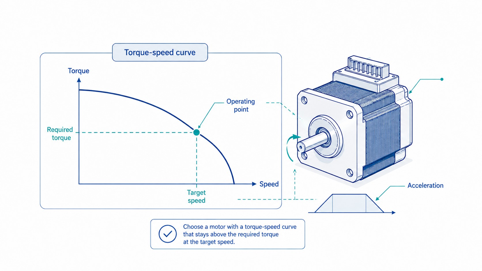
This equation is a useful starting point, but it is not the final selection test. The calculated value must be plotted against the actual motor's speed-torque curve for the proposed driver voltage, current setting and connection. A motor that provides 2.0 N·m holding torque at zero speed may provide only a fraction of that torque at 800, 1,200 or 2,000 rpm.
This guide presents a complete stepper motor sizing workflow for ball screws, lead screws, belts, pulleys, gears, rotary tables, conveyors, CNC axes, 3D printers, robots and industrial automation. It also explains how to prepare a sizing worksheet that can be sent to a motor supplier for engineering review.
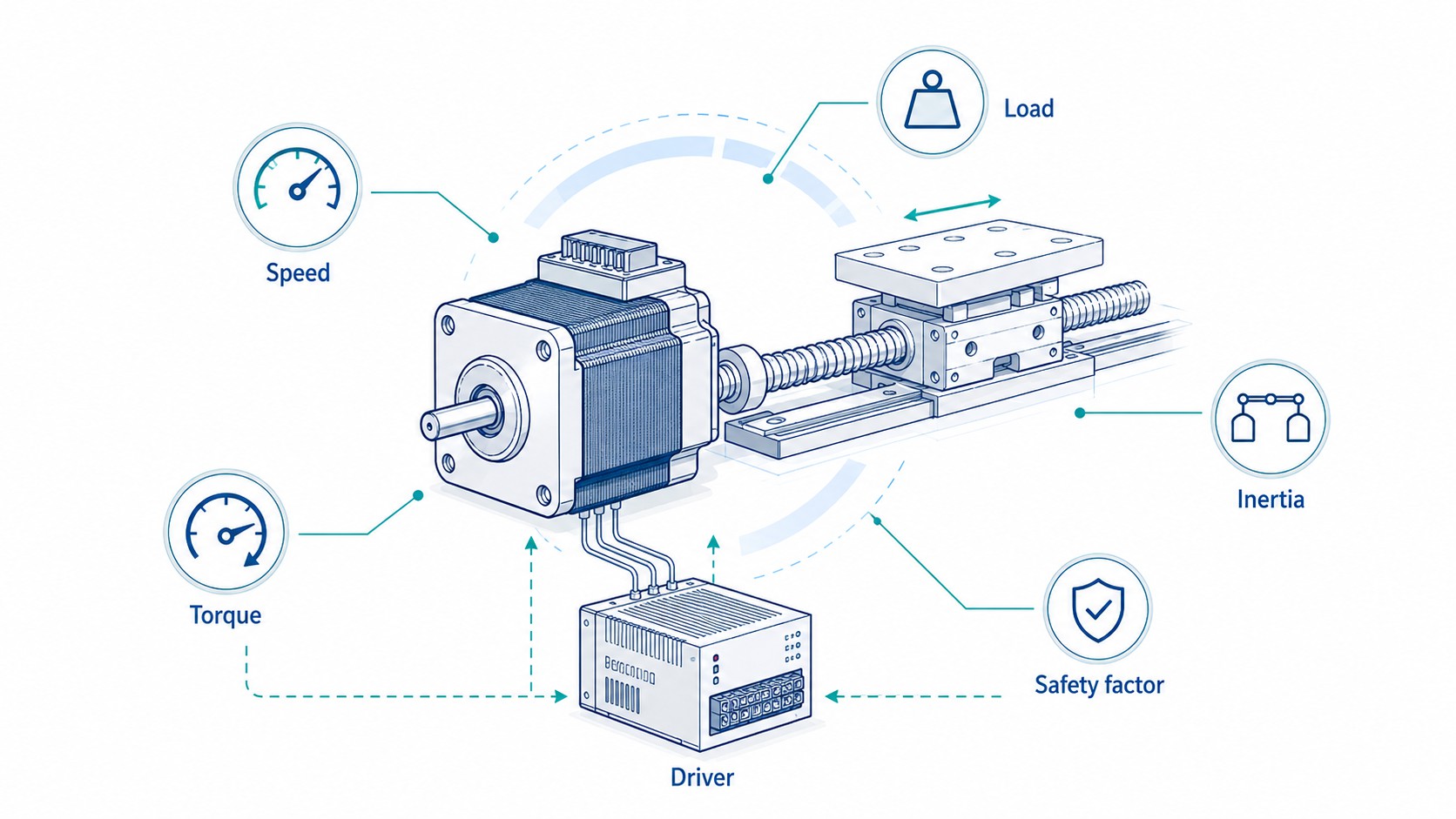
Engineering summary: Calculate the load torque, calculate the acceleration torque, reflect all inertia to the motor shaft, determine the maximum motor speed, select a motor whose torque-speed curve stays above the required torque throughout the motion profile, apply a realistic safety factor, and then verify the driver, power supply, temperature and duty cycle.
Stepper Motor Sizing at a Glance
| Sizing task | What must be determined | Why it matters |
|---|---|---|
| Define the mechanism | Screw, belt, rack, gearbox, direct rotary load or linear actuator | The mechanism determines the torque, speed and reflected inertia formulas |
| Define the motion profile | Travel, maximum speed, acceleration time, deceleration time, dwell and cycle rate | Acceleration often creates more torque demand than steady running |
| Calculate load torque | Friction, gravity, process force, preload and transmission loss | This is the torque needed after acceleration is complete |
| Calculate acceleration torque | Total motor-shaft inertia multiplied by angular acceleration | A high-inertia load can stall a motor even when steady load torque is small |
| Determine motor speed | Linear speed converted through screw lead or pulley circumference | Stepper torque decreases as speed increases |
| Check torque-speed curve | Available running torque at the actual driver voltage and current | Holding torque alone cannot validate the design |
| Apply safety factor | Usually selected from the uncertainty and severity of the application | Covers friction variation, temperature, supply tolerance and unexpected load |
| Match driver and supply | Phase current, voltage range, microstep setting, pulse frequency and braking energy | The driver strongly influences high-speed torque and temperature |
| Check thermal duty | Running current, holding current, ambient temperature, mounting and cycle time | A motor can meet torque requirements but still overheat |
| Validate the machine | Instrumented test at worst-case load, speed and temperature | Calculation reduces risk; machine testing confirms the result |
The required-torque method shown above is also used in the , which calculates required torque from load torque, acceleration torque and a safety factor. Applied Motion Products likewise emphasizes that dynamic stepper sizing must use the available torque at speed rather than the static holding-torque value; see its discussion of .
Why Holding Torque Is Not Enough
Holding torque is the maximum static torque an energized stepper motor can resist at standstill under specified test conditions. It is useful for comparing motors in the same family, but it does not tell you how much torque the motor can produce during acceleration or at the target running speed.
A stepper winding has resistance and inductance. When the drive switches current from one phase state to another, winding current needs time to rise. As speed increases, the electrical commutation period becomes shorter. Back electromotive force also increases with speed. The current may no longer reach the commanded value before the next step, so available torque falls.
Oriental Motor's technical explanation of describes this current-rise limitation and explains why constant-current chopper drives use a supply voltage higher than the motor's simple resistance-based winding voltage. AutomationDirect similarly notes in its that torque decreases substantially as speed approaches the upper operating range.
For this reason, stepper motor selection must answer two different questions:
-
Can the motor provide enough static and low-speed torque?
-
Can the motor provide enough dynamic torque at every speed in the commanded move?
The second question is usually the one that prevents stalls and lost steps.
A practical product comparison
The includes multiple motors with the same nominal frame size but very different electrical and mechanical characteristics. The examples below demonstrate why a NEMA designation does not define torque capability.
| Example motor | Frame and length | Holding torque | Rated current | Inductance | Typical design implication |
|---|---|---|---|---|---|
| 57 mm frame, 25 mm body | 0.33 N·m | 0.9 A/phase | 4.5 mH | Compact and light; suited to low-torque mechanisms where axial length matters | |
| 57 mm frame, 76 mm body | 2.0 N·m | 4.2 A/phase | 2.2 mH | Much higher torque and current; requires a properly matched higher-current driver | |
| 57 mm frame, 56 mm body | 0.9 N·m | 5.2 A/phase | 1.8 mH | Three-phase construction and 1.2° step angle require a compatible three-phase drive | |
| 86 mm frame | 4.5 N·m | 6.0 A/phase | Product-specific | Larger closed-loop option for heavier axes and position-error monitoring |
The correct conclusion is not that one motor is universally better. The conclusion is that frame size, body length, winding current, inductance, rotor inertia, shaft design, encoder option and torque-speed curve must all be considered together.
Define the Load and Motion Before Selecting a Motor
A good motor sizing calculation begins with the machine, not the motor catalog. Collect the following data before calculating torque.
Mechanical data
-
Moving mass in kilograms
-
Rotary load inertia in kg·m², if known
-
Screw lead in meters per revolution or millimeters per revolution
-
Screw diameter and unsupported length
-
Pulley pitch diameter or effective radius
-
Gear ratio and gearbox efficiency
-
Belt reduction or speed-increase ratio
-
Coupling inertia
-
Brake inertia
-
Orientation: horizontal, vertical or inclined
-
Friction coefficient or measured breakaway/running force
-
External process force, such as cutting, pressing, pumping or clamping force
-
Preload force from seals, ball screws, linear bearings or tensioned belts
-
Expected contamination, lubrication condition and temperature range
Motion data
-
Travel distance per move
-
Maximum linear speed or rotary speed
-
Acceleration time
-
Deceleration time
-
Dwell time
-
Repetitions per minute
-
Direction reversals
-
Emergency-stop requirement
-
Required positioning accuracy
-
Required repeatability
-
Acceptable settling time
-
Maximum permitted lost motion or backlash
Electrical and control data
-
Available DC or AC supply
-
Driver current range
-
Driver voltage range
-
Controller pulse-frequency limit
-
Microstep setting
-
Step/direction, CW/CCW, Modbus, CANopen, EtherCAT or other command interface
-
Need for encoder feedback or stall alarm
-
Need for holding brake on a vertical or safety-related axis
A useful rule is to measure uncertain values whenever possible. For example, a spring scale or load cell can measure the actual force needed to move an assembled axis. That measurement captures seal drag, alignment error, guide friction and cable-chain force more accurately than a friction coefficient taken from a catalog.
Calculate Load Torque for the Motion Mechanism
Load torque is the torque required to overcome the steady mechanical load after acceleration is complete. It may include friction, gravity, process force and transmission losses.
The general rotary relationship is:
T = F \times r
$$
where F$ is tangential force and $r is the effective radius. Oriental Motor presents this basic relationship in its guide to .
Belt and pulley drive
For a load moved by a pulley:
T_L = \frac{F_{total} \times r}{\eta}
$$
where:
-
F_{total} = total linear force in newtons
-
r = pulley pitch radius in meters
-
\eta = transmission efficiency as a decimal
For a horizontal axis:
F_{total} = F_{friction} + F_{process} + F_{preload}
$$
For a vertical lifting axis:
F_{total} = mg + F_{friction} + F_{process}
$$
A counterweight, gas spring or constant-force spring can reduce the gravity component, but its force variation across travel must be included.
Lead screw or ball screw drive
For an axial force moved by a screw:
T_L = \frac{F_{total} \times p}{2\pi\eta}
$$
where:
-
p = screw lead in meters per revolution
-
\eta = screw and bearing efficiency
A ball screw often has higher efficiency than a sliding lead screw, but the exact value depends on preload, lubrication, nut design, speed and installation. Do not use an optimistic efficiency value for a dry, contaminated or misaligned mechanism.
For a vertical screw axis, calculate both upward and downward conditions. Upward motion usually has the highest positive torque demand. Downward motion may become overhauling, meaning the load drives the motor. That condition can affect driver bus voltage, braking behavior and the need for a holding brake.
Rack-and-pinion drive
For a pinion with pitch radius r_p:
T_L = \frac{F_{total} \times r_p}{\eta}
$$
If a gearbox is installed between the motor and pinion, reflect the torque through the ratio as described later. Include rack preload and pinion bearing friction.
Direct rotary table
For a rotating table, the steady torque may include bearing friction, seal drag, cable torsion, an off-center gravity load and process torque. If the table rotates around a horizontal axis, gravity torque changes with angle:
T_g = m g e \sin(\theta)
$$
where e is the distance from the rotation axis to the load center of gravity. Use the maximum magnitude over the operating range.
Winding, feeding and conveyor applications
For web winding or unwinding:
T_L = F_{tension} \times r_{roll}
$$
The roll radius changes during operation, so both torque and speed change. A stepper motor may be suitable for low-speed indexed feeding, but continuous tension control with a changing roll diameter often favors a closed-loop stepper, BLDC system or servo.
Calculate Acceleration Torque
Acceleration torque is often underestimated because the steady load force may be small. A low-friction gantry can move easily by hand yet still require high torque to reach speed quickly.
For a rotary system:
T_a = J_{total} \times \alpha
$$
where:
-
J_{total} = total inertia reflected to the motor shaft in kg·m²
-
\alpha = motor angular acceleration in rad/s²
Angular acceleration is:
\alpha = \frac{\omega_2 - \omega_1}{t_a}
$$
and angular velocity is:
\omega = \frac{2\pi n}{60}
$$
where n is speed in rpm.
The total inertia must include:
-
Motor rotor inertia
-
Coupling inertia
-
Pulley or gear inertia
-
Screw inertia
-
Brake inertia
-
Reflected translational mass
-
Reflected rotary loads
-
Reflected gearbox output inertia
Oriental Motor provides a useful companion explanation in and then combines inertia with acceleration in .
Why motor rotor inertia must be included
The motor must accelerate its own rotor as well as the external load. A larger motor can provide more torque, but it also usually has higher rotor inertia. In some fast indexing applications, simply moving to a longer motor can produce less improvement than expected because part of the additional torque is consumed accelerating the heavier rotor.
This is one reason torque-to-inertia performance matters for high-cycle machines.
Reflect Linear and Rotary Inertia to the Motor Shaft
Inertia reflection converts all moving components into an equivalent inertia at the motor shaft. Once every component is expressed at the same shaft, the acceleration-torque calculation becomes straightforward.
Linear mass driven by a screw
For a mass m$ moved by a screw lead $p:
J_{linear} = m\left(\frac{p}{2\pi}\right)^2
$$
Use p in meters per revolution.
A larger screw lead increases linear distance per revolution, which reduces required motor speed for a given linear velocity. However, it also increases the reflected inertia and torque required for a given linear force. Screw lead therefore creates an important speed-versus-torque trade-off.
Linear mass driven by a pulley
For a mass driven directly by a pulley radius r:
J_{linear} = m r^2
$$
A larger pulley reduces motor rpm for the same belt speed, but increases required torque and reflected inertia.
Solid cylinder or pulley
For a solid cylinder rotating around its center:
J = \frac{1}{2}mr^2
$$
Hollow cylinder or roll
For a thick-walled hollow cylinder:
J = \frac{1}{2}m(r_o^2+r_i^2)
$$
Rectangular plate rotating around a central axis
For a rectangular plate rotating around an axis perpendicular to its face through the center:
J = \frac{1}{12}m(a^2+b^2)
$$
Point mass at a radius
For a concentrated mass:
J = mr^2
$$
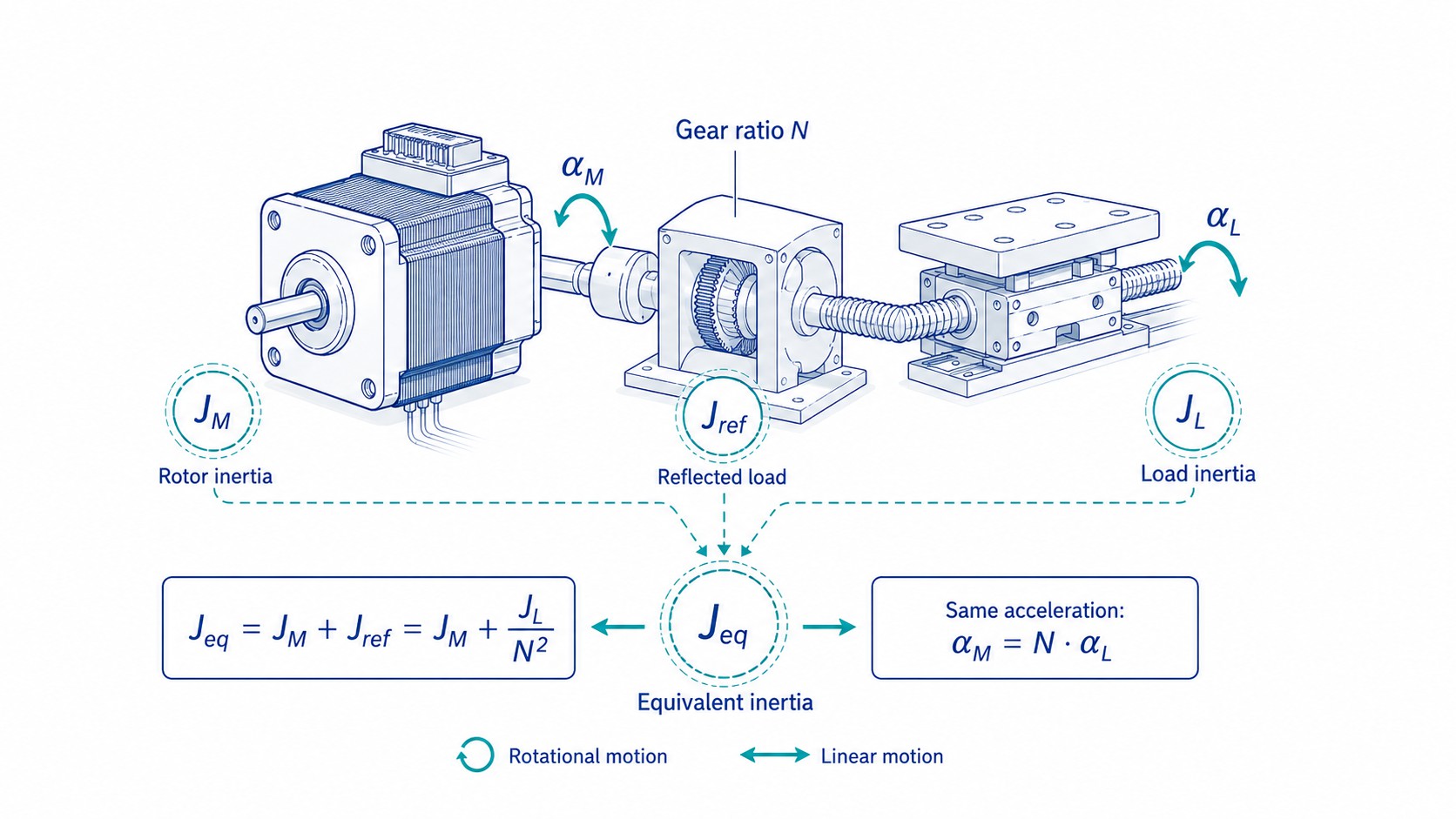
Inertia through a gearbox or belt ratio
Define the reduction ratio as:
i = \frac{\text{motor speed}}{\text{load speed}}
$$
A 5:1 reduction means the motor rotates five revolutions while the load rotates once. Load inertia reflected to the motor is:
J_{reflected} = \frac{J_{load}}{i^2}
$$
This square-law reduction is one of the most valuable reasons to use a gearbox. A 5:1 gearbox reduces the reflected load inertia by 25 times. The trade-offs are higher motor speed, gearbox efficiency loss, backlash, torsional compliance, cost and maximum input-speed limits.
The includes economy and precision planetary options as well as right-angle, spur and worm gearboxes. Gear selection should be based on required output torque, ratio, efficiency, backlash, radial load, service life and allowable input speed, not ratio alone.
Determine the Required Motor Speed
The motor must provide the calculated torque at the required rpm.
Screw-driven linear axis
n = \frac{v}{p} \times 60
$$
where:
-
v = linear speed in meters per second
-
p = screw lead in meters per revolution
-
n = motor speed in rpm for direct drive
Example: a 10 mm lead screw moving at 150 mm/s requires:
n = \frac{0.150}{0.010}\times60 = 900\text{ rpm}
$$
A 5 mm lead screw at the same linear speed requires 1,800 rpm. The finer lead doubles mechanical advantage but also doubles required motor speed. That can be a poor trade for a stepper if the torque-speed curve falls sharply above 1,000 rpm.
Belt-driven axis
n = \frac{v}{\pi D}\times60
$$
where D is pulley pitch diameter.
Gearbox output
For a reduction ratio i:
n_{motor} = n_{load}\times i
$$
A gearbox increases the motor speed required for a given output speed. Always check both the motor torque-speed curve and the gearbox maximum input speed.
Step pulse frequency
The controller must generate enough pulses for the selected microstep setting:
f_{pulse} = \frac{n \times N_{steps/rev}}{60}
$$
For a 1.8° motor there are 200 full steps per revolution. At 16 microsteps, there are 3,200 command pulses per revolution. At 1,200 rpm:
f_{pulse} = \frac{1200\times3200}{60}=64,000\text{ pulses/s}
$$
A controller limited to 50 kHz cannot command that combination of speed and microstep resolution. Reducing the microstep setting may solve the pulse-frequency limit without changing mechanical resolution as much as expected, because microsteps should not be treated as guaranteed load-position accuracy.
Understand Microstepping, Resolution and Accuracy
Microstepping commands intermediate phase-current ratios between full-step positions. It can reduce vibration, audible noise and low-speed roughness. It also increases command resolution.
A 1.8° motor has:
-
200 full steps per revolution
-
400 half steps per revolution
-
1,600 command increments at 8 microsteps
-
3,200 command increments at 16 microsteps
-
51,200 command increments at 256 microsteps
Analog Devices explains the current-vector concept and practical benefits in .
However, command resolution is not the same as accuracy. Actual position is influenced by:
-
Step-angle error
-
Detent torque
-
Load torque
-
Drive current accuracy
-
Motor magnetic symmetry
-
Coupling compliance
-
Belt elasticity
-
Gearbox backlash
-
Screw pitch error
-
Bearing play
-
Structural deflection
-
Thermal expansion
Under load, the rotor may deflect from the ideal microstep equilibrium. Therefore, do not claim that 1/256 microstepping makes a normal mechanical axis 256 times more accurate than full stepping. Use microstepping primarily for smoothness, noise reduction and command granularity, then build a complete mechanical error budget for accuracy.
Use the Speed-Torque Curve Correctly
The torque-speed curve is the decisive catalog document for stepper motor sizing.
A valid curve must match, as closely as possible:
-
Exact motor winding
-
Exact driver or equivalent current-control method
-
Supply voltage
-
Phase current setting
-
Series or parallel winding connection, when applicable
-
Microstep or step mode
-
Test load and measurement method
Pull-in torque and pull-out torque
Some traditional stepper data distinguishes between:
-
Pull-in torque: torque at which the motor can start, stop or reverse without an acceleration ramp
-
Pull-out torque: maximum torque the motor can sustain at speed after it has been accelerated into operation
Modern sizing usually uses a controlled acceleration profile and compares required torque with the dynamic or pull-out curve. Do not assume the motor can instantly start at the final pulse rate.
Plot the required operating points
At minimum, check:
-
Start of acceleration
-
Mid-acceleration
-
End of acceleration at maximum speed
-
Constant-speed process condition
-
Deceleration, especially with an overhauling load
-
Reverse acceleration after a direction change
For a trapezoidal profile, required acceleration torque may be nearly constant while available motor torque decreases with speed. The smallest margin often occurs near the end of acceleration.
Use the lower curve when data is uncertain
If the exact motor-drive-voltage curve is unavailable, do not interpolate optimistically from holding torque. Request the correct curve or test the proposed combination. A conservative selection based on the lower plausible curve is usually less expensive than redesigning a machine after intermittent stalls appear in production.
Applied Motion's illustrates how higher drive voltage can extend the useful torque curve to a higher speed. The principle is important, but the driver voltage must stay within the driver's absolute limits and the motor must remain within thermal limits.
Choose a Safety Factor
The safety factor covers the difference between a clean calculation and a real machine.
Common sources of uncertainty include:
-
Friction that increases as lubrication ages
-
Seal drag
-
Ball-screw preload variation
-
Belt tension variation
-
Cable carrier force
-
Misalignment
-
Supply-voltage tolerance
-
Driver current tolerance
-
Elevated ambient temperature
-
Motor heating and winding resistance increase
-
Machine contamination
-
Process-force spikes
-
Workpiece variation
-
Emergency or abnormal moves
-
Manufacturing tolerances
A practical starting range is often 1.5 to 2.0 for a well-understood industrial axis. Oriental Motor shows a factor of 2 in a worked sizing example, while its application discussions also use lower minimum factors in defined systems. The correct value depends on how well the load is known and how serious a missed step would be.
| Application condition | Suggested engineering approach |
|---|---|
| Laboratory prototype with measured load and low consequence of a stall | A lower factor may be acceptable if the axis is tested over the full operating range |
| Normal industrial automation with predictable load | Start around 1.5 to 2.0 and confirm on the torque-speed curve |
| CNC cutting, dispensing pressure, seals or contamination | Use stronger margin and include measured process-force peaks |
| Vertical lifting axis | Include gravity, brake requirements and failure behavior; do not rely on torque margin alone for safety |
| Human-safety or damage-critical motion | Use appropriate safety architecture, braking and risk assessment; a torque safety factor is not a safety function |
| Uncertain custom mechanism | Measure force, select conservatively and validate at worst-case temperature and supply |
Do not apply the safety factor twice. For example, if you already use a conservative maximum friction force and maximum process force, then apply one documented system safety factor to the combined torque. Keep the assumptions visible so another engineer can review them.
Match the Driver to the Motor
A stepper motor is not a complete system without a compatible driver. Driver selection affects torque, smoothness, noise, heat and protection.
The includes low-current compact drives, higher-current NEMA 23/34 drives, three-phase drives and closed-loop stepper drives. Match the driver to the exact motor current, phase count, feedback type and supply.
Phase current
The driver must support the motor's rated phase current using the same rating convention. Manufacturers may specify peak current, RMS current or a driver-setting value with a conversion. Do not assume a 4.2 A motor should be connected to any driver labeled 4.2 A without checking the manuals.
Too little current reduces torque. Too much current increases copper loss and temperature and may damage the motor or driver.
Supply voltage
Higher supply voltage generally improves current rise and high-speed torque, but voltage must remain within the driver range under all conditions, including line tolerance and regenerative voltage during deceleration.
A motor product page may list a broad recommended drive-voltage range, but final voltage selection should follow the torque-speed curve and driver manual. For example, the is intended for larger motors and supports a much higher supply range than compact low-voltage drives. It should not be substituted into a system without checking current, insulation, heat, control signals and protection.
Texas Instruments notes that stepper system behavior depends on supply voltage, winding inductance and winding resistance in its article on . This is why two motors with the same holding torque can have different high-speed performance.
Microstep setting
Select microstepping to achieve smoothness and manageable pulse frequency. Common practical settings are 8, 10, 16 or 32 microsteps per full step. Very high settings may be useful for quiet motion, but they do not automatically improve load accuracy and can exceed the controller pulse-rate capability.
Idle-current reduction
At standstill, a conventional open-loop drive may continue applying high current to maintain holding torque. Idle-current reduction lowers temperature and power consumption, but it also lowers holding torque. Enable it only after confirming the reduced holding torque is sufficient against gravity, process force and external disturbance.
Closed-loop stepper option
A closed-loop stepper adds encoder feedback and a compatible drive. It can detect position error, optimize current and alarm when the axis cannot follow the command. It does not make an undersized mechanical system unlimited, but it can improve fault detection and load tolerance.
For a detailed technology comparison, see FRANK HU MOTOR's article . Closed-loop steppers are especially useful when a machine needs step/direction simplicity but cannot tolerate unnoticed lost steps.
Select the Power Supply
The power supply must satisfy voltage, average current, peak demand and deceleration behavior.
Voltage selection
Use the driver manufacturer's recommended range and the motor's torque-speed data. A 48 V system often provides better high-speed performance than a 24 V system for a suitable motor and driver, but the higher voltage can increase switching stress and motor heating if current and motion are not configured correctly.
The includes multiple voltage and power options for motion-control systems. A listed supply should still be checked for output tolerance, overload behavior, cooling, regulatory needs and compatibility with the complete machine.
Current sizing
A chopper stepper drive does not draw DC supply current equal to the simple sum of motor phase-current settings at all times. Input current depends on bus voltage, motor speed, load, driver efficiency and current recirculation. Follow the driver manufacturer's power-supply sizing method.
For multi-axis machines, evaluate whether all axes accelerate simultaneously. Diversity can reduce the required continuous supply rating, but a worst-case coordinated move may require substantial peak current.
Deceleration and bus voltage rise
A moving load contains kinetic energy. During deceleration, some systems return energy to the DC bus. A vertical descending load can also regenerate. If the supply cannot absorb the energy, bus voltage may rise and trip or damage the driver. Depending on the driver, solutions may include a braking resistor, regenerative clamp, larger bus capacitance, slower deceleration or a power supply designed to absorb reverse energy.
Check Temperature Rise and Duty Cycle
Stepper motors can run hot even when they are not rotating because holding torque requires winding current. The motor may satisfy the torque calculation and still fail the thermal requirement.
Heat is influenced by:
-
Phase current
-
Winding resistance
-
Driver current waveform
-
Speed
-
Duty cycle
-
Standstill current
-
Ambient temperature
-
Airflow
-
Mounting plate size and material
-
Enclosure temperature
-
Nearby heat sources
-
Motor body length
-
Cable and connector losses
Oriental Motor notes in its discussion of that increasing current also increases operating temperature and can limit duty cycle. Its recommends reducing current when full torque is unnecessary to lower operating temperature.
Thermal validation procedure
-
Mount the motor in the final or thermally equivalent machine structure.
-
Use the intended driver, voltage, current and microstep settings.
-
Run the worst realistic motion cycle, including dwell with holding current.
-
Use the highest expected ambient temperature.
-
Measure motor case temperature and, when possible, driver temperature.
-
Continue until temperature stabilizes; a short test can miss slow heat accumulation.
-
Confirm cable, connector and power-supply temperature.
-
Repeat with the highest expected mechanical load and friction.
The permissible case temperature depends on insulation class, bearings, grease, encoder, brake, cable and application requirements. Do not use a universal hand-touch rule. A motor that is too hot to touch may still be inside its electrical rating, but it may be unacceptable near plastic parts, sensors, adhesives, operators or temperature-sensitive instruments.
Worked Example: Ball-Screw Positioning Axis
Consider a horizontal automation axis with these requirements:
| Input | Value |
|---|---|
| Moving mass | 18 kg |
| Ball-screw lead | 10 mm/rev |
| Screw diameter | 16 mm |
| Screw length | 800 mm |
| Screw efficiency | 0.90 |
| Linear-guide friction coefficient | 0.03 |
| External process force | 40 N |
| Maximum linear speed | 150 mm/s |
| Acceleration time | 0.30 s |
| Candidate motor rotor inertia | 4.8\times10^{-5} kg·m² |
| Coupling inertia | 3.0\times10^{-6} kg·m² |
| Safety factor | 1.8 |
This example is intentionally transparent. A real project should replace assumed values with measured or supplier-certified data.
1. Calculate friction force
F_f = \mu mg
$$
F_f = 0.03\times18\times9.81 = 5.30\text{ N}
$$
2. Calculate total steady force
F_{total}=F_f+F_{process}=5.30+40=45.30\text{ N}
$$
3. Calculate load torque
Convert the lead to meters per revolution:
p=10\text{ mm/rev}=0.010\text{ m/rev}
$$
T_L=\frac{F_{total}p}{2\pi\eta}
$$
T_L=\frac{45.30\times0.010}{2\pi\times0.90}=0.080\text{ N·m}
$$
The steady torque is small because the ball screw provides substantial mechanical advantage.
4. Calculate reflected inertia of the moving mass
J_{mass}=m\left(\frac{p}{2\pi}\right)^2
$$
J_{mass}=18\left(\frac{0.010}{2\pi}\right)^2=4.56\times10^{-5}\text{ kg·m}^2
$$
5. Estimate screw inertia
First calculate screw mass using steel density of approximately 7,850 kg/m³:
m_s=\rho\pi\left(\frac{d}{2}\right)^2L
$$
m_s\approx1.263\text{ kg}
$$
Treating the screw as a solid cylinder:
J_s=\frac{1}{2}m_s\left(\frac{d}{2}\right)^2
$$
J_s\approx4.04\times10^{-5}\text{ kg·m}^2
$$
6. Add external inertia
J_{external}=J_{mass}+J_s+J_{coupling}
$$
J_{external}=4.56\times10^{-5}+4.04\times10^{-5}+0.30\times10^{-5}
$$
J_{external}=8.90\times10^{-5}\text{ kg·m}^2
$$
Including the candidate motor rotor:
J_{total}=8.90\times10^{-5}+4.80\times10^{-5}=1.37\times10^{-4}\text{ kg·m}^2
$$
7. Calculate maximum motor speed
n=\frac{v}{p}\times60
$$
n=\frac{0.150}{0.010}\times60=900\text{ rpm}
$$
8. Calculate angular acceleration
Final angular speed:
\omega=\frac{2\pi\times900}{60}=94.25\text{ rad/s}
$$
\alpha=\frac{94.25}{0.30}=314.16\text{ rad/s}^2
$$
9. Calculate acceleration torque
T_a=J_{total}\alpha
$$
T_a=1.37\times10^{-4}\times314.16=0.043\text{ N·m}
$$
10. Calculate required torque with safety factor
T_M=(T_L+T_a)\times S_f
$$
T_M=(0.080+0.043)\times1.8=0.222\text{ N·m}
$$
11. Interpret the result
The motor-drive combination must provide at least 0.222 N·m at approximately 900 rpm, not merely 0.222 N·m at standstill. The selected curve should also have adequate margin through the acceleration range.
A NEMA 23 motor with 1.2 or 2.0 N·m holding torque might appear oversized from the static calculation, yet the actual decision depends on its 900 rpm torque at the selected bus voltage. A compact high-inductance motor may not have enough speed margin, while a lower-inductance winding on a suitable higher-voltage drive may perform well.
The load-to-motor inertia ratio in this example is:
\frac{J_{external}}{J_{motor}}=\frac{8.90\times10^{-5}}{4.80\times10^{-5}}=1.85
$$
This is a manageable ratio for many systems, but the final acceptance criterion must come from the motor and driver manufacturer.
12. Check pulse frequency
At 16 microsteps:
N_{steps/rev}=200\times16=3200
$$
f_{pulse}=\frac{900\times3200}{60}=48,000\text{ pulses/s}
$$
The controller must sustain at least 48 kHz for this axis, with additional margin for command timing and multi-axis interpolation.
13. Check the thermal cycle
Assume the axis accelerates for 0.30 s, runs for 1.2 s, decelerates for 0.30 s and dwells for 2.0 s. The motor may spend more time holding than moving. If full holding current is unnecessary, configure idle-current reduction and verify that the lower holding torque still resists process force and external disturbance.
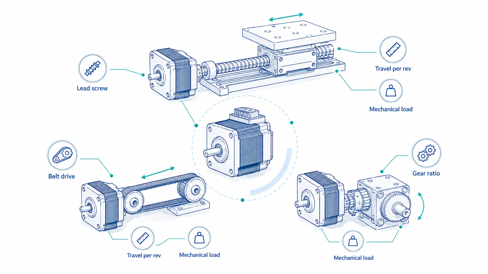
How Transmission Choices Change the Motor Size
The motion mechanism often has more influence on motor selection than moving from one motor frame to another.
Screw lead trade-off
For a fixed linear speed:
-
Smaller lead increases motor rpm
-
Smaller lead reduces required force torque
-
Smaller lead reduces reflected linear inertia
-
Larger lead reduces motor rpm
-
Larger lead increases torque demand
-
Larger lead increases reflected linear inertia
If a design requires 300 mm/s, a 5 mm lead screw needs 3,600 rpm, which is generally unattractive for a direct-drive stepper. A 20 mm lead needs 900 rpm, but requires four times the torque for the same axial force and reflects 16 times the linear inertia. The correct lead must balance speed, torque, inertia, resolution, screw critical speed and buckling.
Pulley diameter trade-off
For a fixed belt speed:
-
Smaller pulley increases motor rpm and reduces torque
-
Larger pulley reduces motor rpm and increases torque
-
Reflected linear inertia changes with the square of pulley radius
A slightly smaller pulley can improve acceleration torque significantly, but very small pulleys may reduce belt life, tooth engagement and stiffness.
Gear reduction trade-off
A reduction gearbox:
-
Multiplies output torque approximately by ratio and efficiency
-
Reduces reflected load inertia by the square of the ratio
-
Increases motor speed by the ratio
-
Adds backlash, compliance, cost and efficiency loss
For low-speed high-torque mechanisms, a geared stepper can be more compact than an oversized direct-drive motor. For precise reversing motion, use a low-backlash gearbox and include torsional stiffness in the positioning analysis.
Open-Loop Stepper, Closed-Loop Stepper or Servo?
Correct sizing sometimes shows that a stepper is not the best technology.
| Requirement | Open-loop stepper | Closed-loop stepper | Servo |
|---|---|---|---|
| Low-speed point-to-point motion | Excellent value | Excellent where fault detection matters | Usually capable but may be unnecessarily complex |
| High holding torque at zero speed | Strong with current applied | Strong with feedback monitoring | Active holding; brake may still be required |
| High speed under load | Limited by torque decay | Better utilization, but still stepper-based | Usually strongest option |
| Rapid acceleration and short cycle | Possible with low inertia and proper sizing | Better diagnostics | Usually best dynamic performance |
| Unnoticed lost steps unacceptable | Risk unless external verification is used | Encoder can alarm or correct within limits | Continuous feedback is standard |
| Simple pulse/direction retrofit | Very easy | Easy | Often possible but may require more setup |
| Heat at standstill | Can be high | Often reduced by adaptive current | Current follows load demand more closely |
| Wide load variation | Requires conservative sizing | Better tolerance | Best disturbance response |
If the calculated operating point is near the edge of every plausible stepper torque curve, do not solve the problem by using an extreme safety factor and a very large motor. Consider changing the transmission, increasing acceleration time, reducing speed, using a closed-loop stepper or moving to a servo system.
NEMA Frame Size: What It Does and Does Not Tell You
A NEMA frame designation primarily standardizes mounting dimensions. It does not guarantee body length, holding torque, current, inductance, rotor inertia, shaft size, connector, IP rating or high-speed performance.
The spans compact NEMA 6 and NEMA 8 designs through NEMA 34, NEMA 42 and NEMA 51 products. Within one frame, longer stacks usually provide more holding torque, but they may also increase rotor inertia and current demand.
Use frame size late in the process:
-
Calculate torque, speed and inertia.
-
Identify motor-drive combinations with adequate dynamic margin.
-
Compare rotor inertia, thermal performance and electrical requirements.
-
Confirm that the frame, shaft and body length fit the machine.
-
Confirm cable, connector, encoder, brake and environmental options.
This prevents the common mistake of starting with “NEMA 23 should be enough” before any calculation has been completed.
Common Stepper Motor Sizing Mistakes
Selecting from holding torque only
Holding torque is measured at zero speed. Use the running torque at the actual speed.
Ignoring acceleration torque
A low-friction axis may have small steady torque but large acceleration torque. Calculate inertia and angular acceleration.
Ignoring motor rotor inertia
The motor accelerates itself. Include rotor inertia in J_{total}.
Using the wrong screw units
Convert millimeters per revolution to meters per revolution before using SI formulas.
Confusing gear ratio direction
Document the ratio definition. In this guide, i = n_{motor}/n_{load}.
Forgetting gearbox efficiency
Output torque is not equal to motor torque multiplied by the ideal ratio. Include efficiency and verify rated output torque.
Treating microsteps as guaranteed accuracy
Microstepping improves command resolution and smoothness, not necessarily proportional load accuracy.
Ignoring pulse-frequency limits
High rpm combined with high microstepping can exceed controller output frequency.
Choosing voltage from the motor resistance only
A current-regulated chopper drive often uses a supply much higher than the simple I\times R winding voltage. Follow the driver and motor curve data.
Matching peak current to RMS current incorrectly
Confirm how the driver and motor specify current.
Ignoring vertical-axis failure behavior
A stepper's holding torque disappears or decreases when power is removed. Use a properly rated brake or counterbalance where a falling load creates risk.
Ignoring temperature rise
Test the final duty cycle with the real mount, enclosure and ambient temperature.
Using an oversized motor as the only solution
A larger motor adds rotor inertia and may require a larger driver and power supply. Improve the transmission or motion profile first.
Failing to test worst-case friction
A newly assembled, cool, well-lubricated machine may not represent production conditions after contamination, temperature change or cable aging.
Stepper Motor Sizing Worksheet
The following worksheet can be copied into a project specification, spreadsheet or online inquiry form.
Project identification
| Field | Entry |
|---|---|
| Project or machine name | |
| Axis name | |
| Application | CNC / robotics / 3D printing / packaging / laboratory / other |
| Prototype quantity | |
| Estimated annual quantity | |
| Required delivery date |
Load and mechanism
| Field | Symbol | Unit | Entry |
|---|---|---|---|
| Moving load mass | m | kg | |
| Rotary load inertia | J_L | kg·m² | |
| Motion orientation | — | horizontal / vertical / inclined | |
| Transmission type | — | screw / belt / rack / gearbox / direct rotary | |
| Screw lead | p | mm/rev | |
| Screw diameter | d | mm | |
| Screw length | L | mm | |
| Pulley pitch diameter | D | mm | |
| Gear ratio | i | motor rev/load rev | |
| Transmission efficiency | \eta | % | |
| Friction force | F_f | N | |
| Process force | F_p | N | |
| Gravity or counterbalance force | F_g | N | |
| Coupling inertia | J_c | kg·m² | |
| Gearbox/pulley inertia at motor | J_t | kg·m² |
Motion profile
| Field | Symbol | Unit | Entry |
|---|---|---|---|
| Travel distance | s | mm | |
| Maximum linear speed | v | mm/s | |
| Maximum rotary speed | n | rpm | |
| Acceleration time | t_a | s | |
| Constant-speed time | t_c | s | |
| Deceleration time | t_d | s | |
| Dwell time | t_w | s | |
| Cycles per minute | — | cycles/min | |
| Direction reversals | — | per cycle | |
| Emergency-stop time | — | s |
Accuracy and environment
| Field | Unit | Entry |
|---|---|---|
| Required positioning accuracy | mm or degree | |
| Required repeatability | mm or degree | |
| Maximum backlash | arcmin or mm | |
| Ambient temperature | °C | |
| Enclosure temperature | °C | |
| Protection requirement | IP rating | |
| Dust, coolant, vacuum or cleanroom | description | |
| Noise limit | dBA or qualitative | |
| Required brake | yes/no | |
| Required encoder | open loop / incremental / absolute |
Electrical and controller
| Field | Unit | Entry |
|---|---|---|
| Available supply | VDC or VAC | |
| Maximum driver current | A | |
| Controller pulse limit | kHz | |
| Control interface | step/direction / fieldbus / I/O | |
| Preferred microstep setting | microsteps/full step | |
| Cable length | m | |
| Connector requirement | description |
Calculation results
| Result | Symbol | Unit | Value |
|---|---|---|---|
| Load torque | T_L | N·m | |
| External reflected inertia | J_{external} | kg·m² | |
| Candidate motor rotor inertia | J_M | kg·m² | |
| Total inertia | J_{total} | kg·m² | |
| Maximum motor speed | n_{max} | rpm | |
| Angular acceleration | \alpha | rad/s² | |
| Acceleration torque | T_a | N·m | |
| Safety factor | S_f | — | |
| Required motor torque | T_M | N·m | |
| Required pulse frequency | f_{pulse} | Hz | |
| Available curve torque at max speed | T_{curve} | N·m | |
| Torque margin | T_{curve}/T_M | ratio | |
| Load-to-motor inertia ratio | J_{external}/J_M | ratio |
Information to Send for a Motor Recommendation
A supplier can make a much stronger recommendation when the inquiry includes the complete motion profile. Send:
-
Load mass or rotary inertia
-
Screw lead, pulley diameter or gearbox ratio
-
Maximum speed
-
Acceleration and deceleration time
-
Horizontal or vertical orientation
-
Friction and process force
-
Duty cycle
-
Required accuracy and repeatability
-
Available voltage
-
Controller interface and pulse-frequency limit
-
Environmental requirements
-
Shaft, cable, connector, brake and encoder requirements
-
Prototype and annual quantities
FRANK HU MOTOR supports standard and custom stepper motor configurations, including shafts, windings, encoders, brakes, gearboxes, cables and integrated drives. Use the to submit the worksheet and request a motor-drive recommendation.
Frequently Asked Questions
How do I calculate the torque required for a stepper motor?
Calculate the steady load torque, calculate the acceleration torque from total motor-shaft inertia and angular acceleration, add them, and multiply by a documented safety factor:
T_M=(T_L+T_a)\times S_f
$$
Then confirm that the motor's torque-speed curve provides more than T_M at the required speed.
What safety factor should I use for stepper motor sizing?
A common starting range is 1.5 to 2.0 for a well-understood industrial mechanism, but the correct value depends on uncertainty, load variation, temperature, contamination and the consequence of a stall. A safety factor is not a substitute for a correct speed-torque curve or machine validation.
Is holding torque the same as running torque?
No. Holding torque is measured at standstill. Running torque decreases with speed and depends strongly on the motor winding, driver, current and supply voltage.
How do I calculate stepper motor speed for a lead screw?
For direct drive:
n=\frac{v}{p}\times60
$$
Use linear speed v$ in meters per second and screw lead $p in meters per revolution.
How do I calculate reflected inertia for a lead screw?
For a translating mass:
J_{linear}=m\left(\frac{p}{2\pi}\right)^2
$$
Add the screw, coupling, pulley, gearbox and motor rotor inertia before calculating acceleration torque.
What is a good load-to-motor inertia ratio for a stepper?
There is no universal limit. Many practical systems target a modest ratio, and some drive documentation uses ranges such as below 10:1 for conventional applications. The acceptable ratio depends on the motor, driver damping, acceleration profile, coupling stiffness and feedback. Follow the specific manufacturer's recommendation and validate the system.
Does a gearbox reduce inertia?
A reduction gearbox reduces load inertia reflected to the motor by the square of the ratio:
J_{reflected}=\frac{J_{load}}{i^2}
$$
It also increases motor speed and adds backlash, compliance and efficiency loss.
Does higher voltage increase stepper motor torque?
Higher driver bus voltage can improve high-speed torque by increasing the rate of winding-current rise. It does not increase the permitted phase current, and it must remain within driver and insulation limits. Use a torque-speed curve for the intended voltage.
Does microstepping increase torque?
Microstepping mainly improves smoothness, noise and command resolution. It does not multiply the motor's available torque. Very small microstep increments may not produce proportional shaft movement under load.
How hot can a stepper motor run?
The allowable temperature depends on insulation class, bearings, grease, encoder, brake, cable and installation. Use the product specification and measure temperature in the final duty cycle. Reduce current or improve cooling if temperature is excessive.
When should I use a closed-loop stepper?
Use a closed-loop stepper when you want step/direction simplicity and strong low-speed behavior but need position-error detection, stall alarms, lower heat or better response to load variation. It is not a replacement for correct sizing.
When should I choose a servo instead?
Choose a servo when the machine requires sustained high-speed torque, very rapid acceleration, wide speed range, aggressive disturbance rejection, coordinated contouring or large load variation. Review the complete application rather than assuming that either technology is always superior.
Can I size a motor from load weight alone?
No. Weight must be converted through the mechanism, and the calculation also needs speed, acceleration, orientation, friction, process force, inertia, duty cycle and the driver voltage.
Why does my stepper work slowly but stall at production speed?
The most common reasons are insufficient running torque at speed, acceleration that is too aggressive, low supply voltage, excessive winding inductance, incorrect current setting, mechanical resonance or underestimated friction. Compare the operating point with the correct torque-speed curve.
Can I simply increase the current to stop missed steps?
Increasing current may increase low-speed torque up to the motor's permitted rating, but it also increases heat. If the motor already uses rated current, further increase can damage the motor or driver. Improve the motion profile, voltage, mechanism or motor selection instead.
Final Selection Checklist
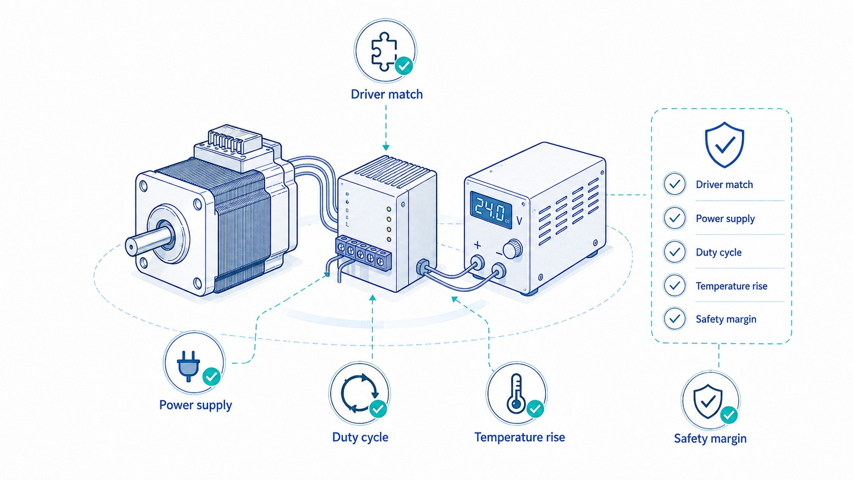
Before approving the motor-drive system, confirm all of the following:
-
The mechanism and load data are documented.
-
Load torque includes friction, gravity, process force and efficiency.
-
Acceleration torque includes motor rotor inertia and all reflected inertia.
-
Maximum motor rpm is calculated from the transmission.
-
Controller pulse frequency is sufficient at the selected microstep setting.
-
The exact torque-speed curve stays above required torque through the motion profile.
-
The safety factor is documented and not applied twice.
-
Driver phase current matches the motor and uses the correct RMS/peak convention.
-
Driver voltage is suitable for the desired speed and within all limits.
-
The power supply supports average and peak demand.
-
Deceleration and vertical-load regeneration are addressed.
-
Load-to-motor inertia ratio is within the manufacturer's recommendation.
-
Motor case and driver temperature are tested at worst-case duty and ambient temperature.
-
Holding-current reduction does not compromise the stationary load.
-
A brake or counterbalance is provided where loss of power could cause dangerous motion.
-
Accuracy is evaluated at the load, including backlash, compliance and screw or belt error.
-
The complete axis is tested at maximum load, speed, acceleration and temperature.
Conclusion
A dependable stepper motor sizing calculation connects the mechanical load, motion profile, transmission, motor, driver, power supply and thermal environment. The basic equation
T_M=(T_L+T_a)\times S_f
$$
is the center of the calculation, but the final selection must be proven against the dynamic torque-speed curve at the required rpm.
Start by defining the mass, force, mechanism, speed and acceleration. Calculate steady load torque. Reflect all inertia to the motor shaft and calculate acceleration torque. Evaluate screw lead, pulley diameter or gearbox ratio. Determine the highest motor speed and pulse frequency. Apply a justified safety factor. Then verify the exact motor-driver-voltage curve, driver current convention, supply capability, temperature rise and duty cycle.
When these steps are followed, stepper motor selection becomes a traceable engineering decision rather than a guess based on NEMA frame size or holding torque. The result is a machine with fewer stalls, lower heat, better positioning reliability and a clearer path from prototype to production.
For project-specific selection, browse the , , , and , then send the completed sizing worksheet through the