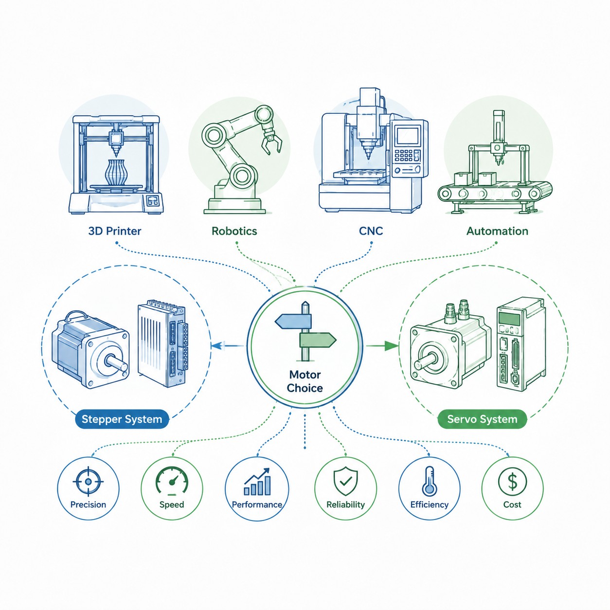
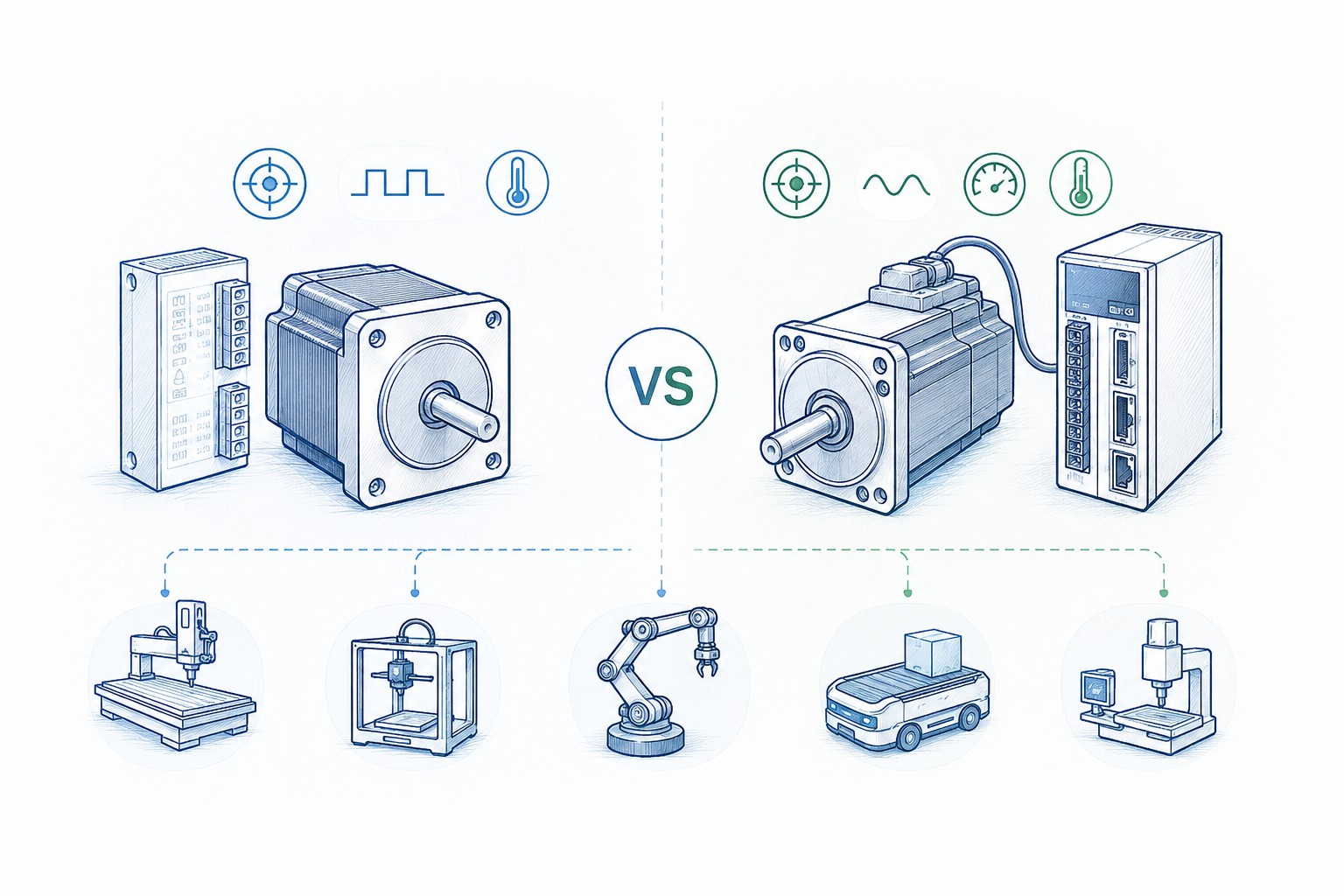
Choosing between a stepper motor and a servo motor is not simply a matter of asking which technology is “better.” The correct question is: Which motor-drive system delivers the required torque, speed, accuracy, reliability and lifecycle cost for this specific machine?
For many low-speed positioning tasks, a properly sized stepper system is the most practical and economical solution. It can deliver strong low-speed torque, repeatable indexed motion, simple pulse-and-direction control and useful holding torque without requiring servo tuning. For high-speed machines, rapidly changing loads, aggressive acceleration, coordinated multi-axis motion or wide operating-speed ranges, a servo system usually provides the stronger performance margin.
There is also a third option between these two familiar choices: the closed-loop stepper, sometimes marketed as a stepper servo. It combines the high pole count and low-speed behavior of a stepper motor with encoder feedback that can detect position error, reduce the risk of unnoticed lost steps and improve current control.
This guide compares all three approaches from an engineering and purchasing perspective. It covers low-speed torque, high-speed torque decay, positioning accuracy, repeatability, missed-step risk, encoder feedback, tuning, holding torque, heat, efficiency, cost, load inertia and application-specific selection for CNC machines, 3D printers, robots and industrial automation.
Fast answer: Choose an open-loop stepper for economical low-speed positioning with predictable loads. Choose a closed-loop stepper when you want stepper simplicity but need error detection and better load tolerance. Choose a servo when speed, acceleration, dynamic response and disturbance rejection determine machine productivity.
Quick Decision Table
| Project condition | Recommended solution | Why |
|---|---|---|
| Low speed, high holding torque, cost-sensitive | Open-loop stepper | Strong low-speed torque, simple control and low system cost |
| Concerned about missed steps but budget is limited | Closed-loop stepper | Encoder feedback adds position monitoring and correction without moving fully to a servo platform |
| High speed and high dynamic response | Servo | Broad torque-speed range, peak torque and high control bandwidth |
| Load changes significantly during operation | Closed-loop stepper or servo | Feedback allows the drive to react to position error and changing torque demand |
| CNC woodworking router or engraving machine | NEMA 23/34 stepper or closed-loop stepper | Practical torque and cost for moderate feed rates and predictable cutting loads |
| High-speed metal machining equipment | Servo system | Better high-speed torque, acceleration, contouring response and overload recovery |
| Desktop or industrial 3D printer | Stepper; closed-loop stepper for demanding axes | High resolution, low-speed control, low cost and easy multi-axis integration |
| Fast pick-and-place robot or coordinated robotic arm | Servo | Low rotor inertia, high acceleration, continuous feedback and rapid disturbance correction |
FRANK HU MOTOR supplies a broad range of , , and for motion-control projects from compact instruments to CNC equipment and industrial automation.
What Is the Fundamental Difference Between a Stepper Motor and a Servo Motor?
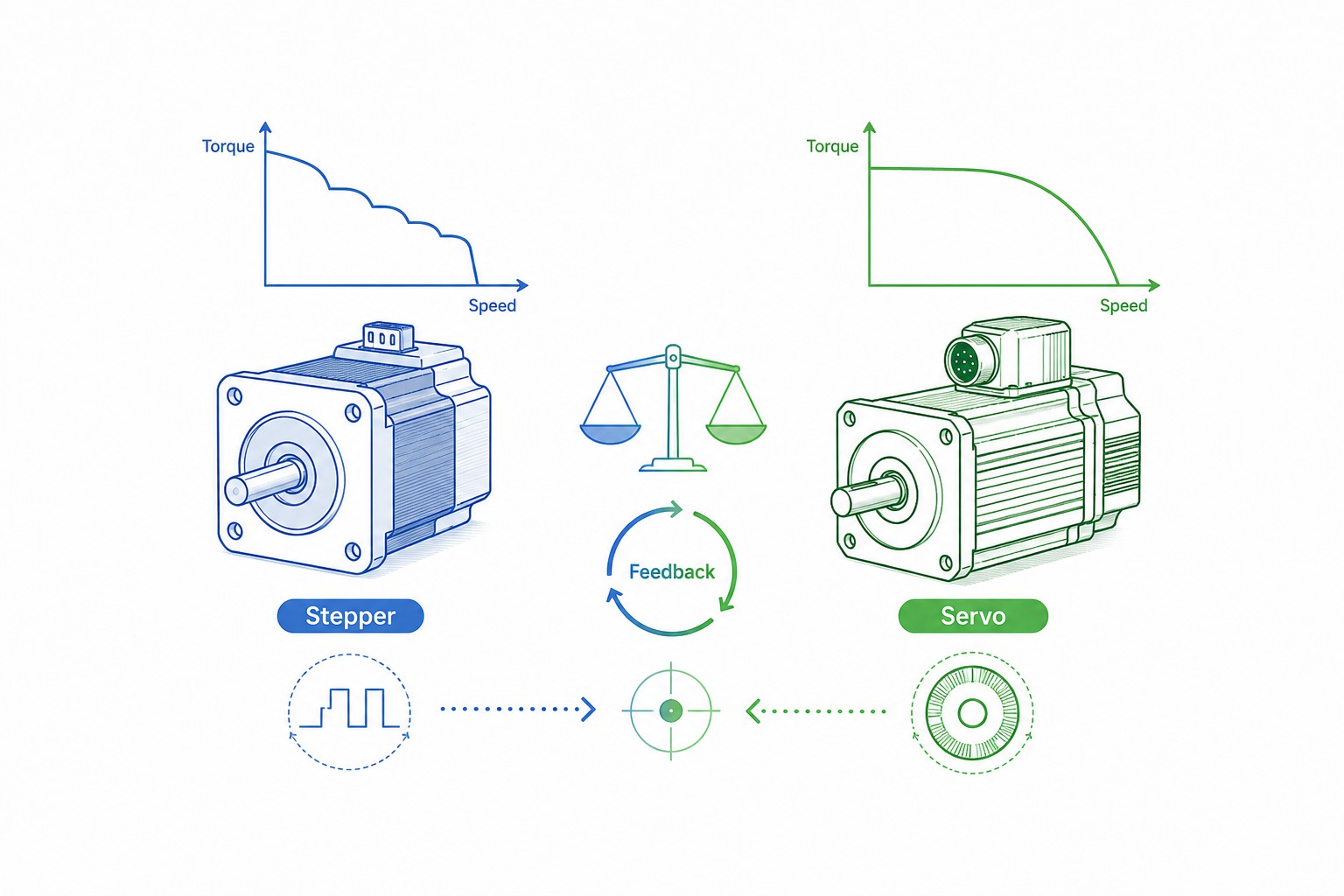
A stepper motor moves in discrete electromagnetic increments. A common two-phase hybrid stepper has a 1.8-degree full-step angle, which corresponds to 200 full steps per revolution. The controller sends step pulses, and the drive energizes the windings in a sequence that advances the rotor from one stable magnetic position to the next. In an open-loop system, the controller assumes that each commanded step has been completed.
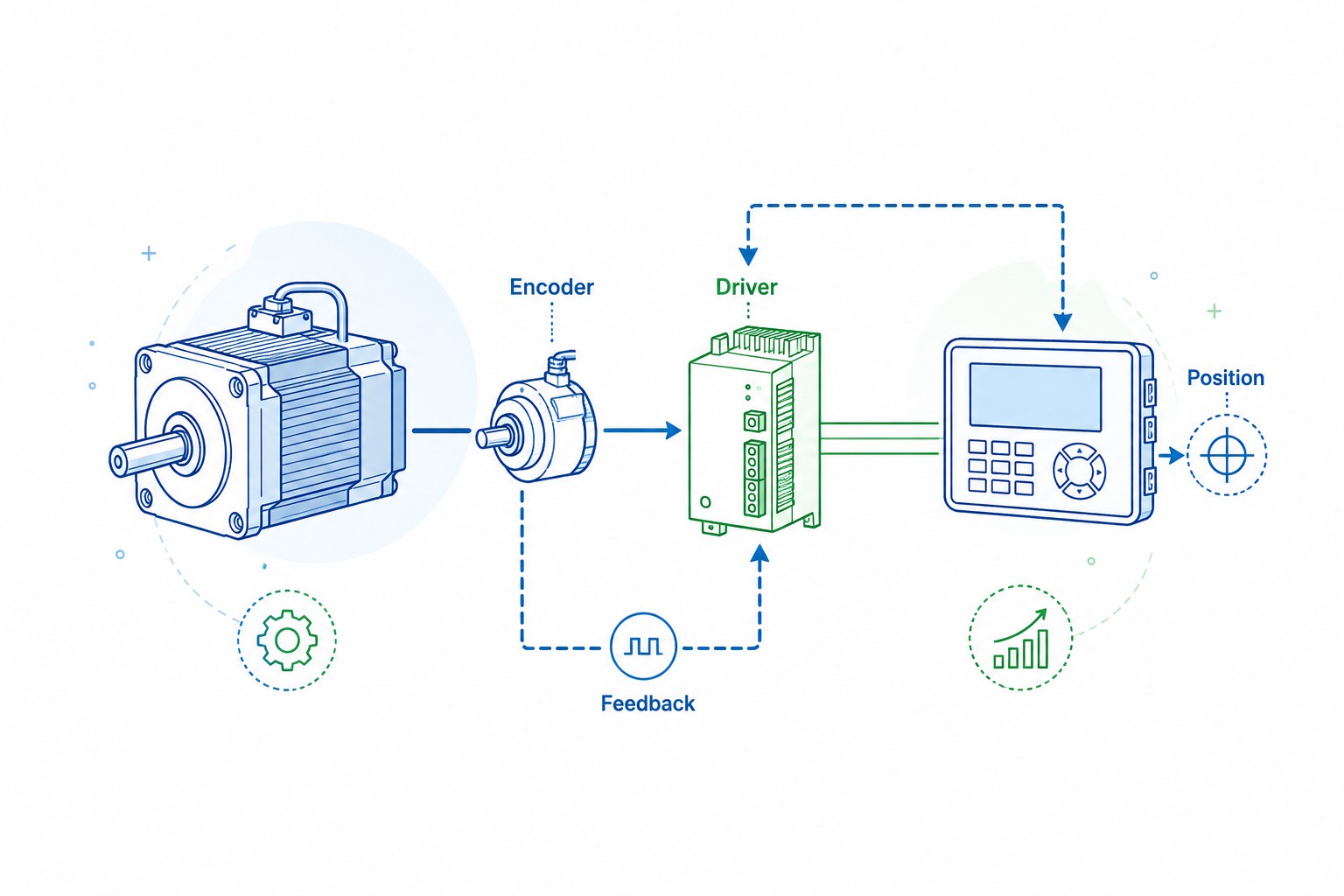
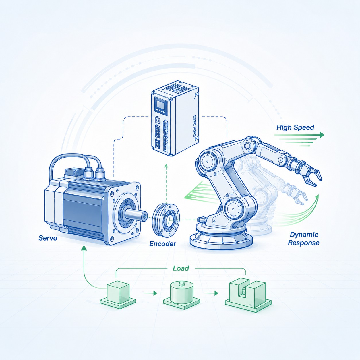
A servo motor is part of a feedback-controlled system. The motor normally uses an encoder or resolver to report rotor position and speed to the servo drive. The drive continuously compares the command with the measured response and adjusts motor current to reduce the error. Position, velocity and current loops operate together, allowing the servo to respond to changing loads and disturbances.
This difference creates the practical contrast:
-
A stepper system is naturally suited to commanded incremental positioning.
-
A servo system is naturally suited to continuous error correction and dynamic motion control.
-
A closed-loop stepper uses stepper motor construction but adds feedback, creating a hybrid solution between traditional open-loop steppers and conventional servos.
The comparison is not purely about the motor. The performance of either technology depends on the complete system: motor winding, drive voltage, current setting, encoder, controller, mechanical transmission, load inertia, acceleration profile, coupling stiffness, thermal environment and cable quality.
Stepper Motor vs Servo Motor at a Glance
| Selection factor | Open-loop stepper | Closed-loop stepper | Servo motor system |
|---|---|---|---|
| Control principle | Commanded steps without continuous position feedback | Step commands with encoder-based position monitoring or correction | Closed-loop position, speed and current regulation |
| Low-speed torque | Usually excellent for frame size | Excellent, often with better current utilization | Good, with strong intermittent peak torque depending on system |
| High-speed torque | Falls substantially as speed rises | Better utilization than open loop, but still limited by stepper electrical characteristics | Maintains useful torque over a much wider speed range |
| Holding at zero speed | Strong energized holding torque | Strong holding torque with feedback supervision | Can hold position actively; brake may be required for vertical or safety-critical axes |
| Missed-step risk | Possible if available torque is exceeded | Detected and often corrected within system limits | Position error is continuously monitored; drive can alarm on excessive following error |
| Encoder | Usually none | Incremental or absolute encoder | Incremental, absolute encoder or resolver is standard |
| Tuning | Minimal | Usually light or simplified | Auto-tuning is common, but high-performance machines may still need engineering adjustment |
| Heat at standstill | Can be high if full current is maintained | Usually lower with load-based or idle-current control | Current is generally supplied according to required torque |
| Efficiency | Good in the correct operating region; less efficient when continuously overdriven | Improved relative to open-loop operation | Typically better over variable loads and higher duty cycles |
| Initial cost | Lowest | Medium | Highest hardware and integration cost |
| Best operating region | Low to moderate speed, predictable load, point-to-point motion | Low to moderate speed with changing load or lost-step concerns | High speed, wide speed range, high acceleration, coordinated motion |
A widely referenced Kollmorgen engineering guide shows the characteristic difference between similarly sized systems: a stepper can produce higher continuous torque at very low speed, while a servo provides continuous and peak torque across a much broader and higher speed range. The same guide notes that stepper torque commonly begins to fall significantly as speed rises, whereas comparable servo systems can continue operating at several thousand revolutions per minute. See Kollmorgen’s technical paper, .
Low-Speed Torque: Why Steppers Are So Effective Near Standstill
Stepper motors are frequently selected for low-speed axes because they can generate substantial torque at zero or low rotational speed without a gearbox. Their toothed rotor and stator structure creates many magnetic alignment positions per revolution, and the energized phases provide a stiff restoring torque around each commanded position.
This is useful in applications such as:
-
indexing tables;
-
label and packaging adjustments;
-
syringe pumps and laboratory dosing mechanisms;
-
low-speed lead-screw stages;
-
desktop CNC machines;
-
3D printer extruders and Z axes;
-
camera and optical positioning mechanisms;
-
valve and damper adjustment.
However, holding torque is not the same as usable running torque. Holding torque is measured at standstill under specified current and thermal conditions. Once the motor accelerates, the available torque falls. A sound design should use the manufacturer’s torque-speed curve for the exact motor-drive-voltage combination rather than applying a fixed percentage of the holding-torque value.
For example, FRANK HU MOTOR lists hybrid steppers from compact NEMA 6 and NEMA 8 frames through NEMA 23, NEMA 34 and larger industrial frames in its . The frame designation primarily describes mounting dimensions. It does not guarantee torque, current, inductance or speed capability. Two NEMA 23 motors may have very different body lengths, winding constants and torque-speed curves.
Practical low-speed sizing rule
For an open-loop stepper, the motor should have adequate margin at the actual operating speed, not merely at standstill. The available torque at every point in the acceleration and running profile should exceed the combined demand from:
-
load acceleration;
-
friction;
-
gravity on vertical axes;
-
machining or process force;
-
transmission losses;
-
disturbance margin.
A common engineering mistake is to choose a motor whose holding torque is only slightly above the calculated load torque. That design may work during slow testing but stall during rapid acceleration, high-temperature operation, reduced supply voltage or an unexpected process load.
High-Speed Torque Decay: The Main Limitation of Stepper Systems
The most important difference in the stepper motor vs servo motor decision often appears at higher speed.
A stepper winding has resistance and inductance. Current cannot rise instantly when the drive switches the phase voltage. As electrical stepping frequency increases, there is less time for winding current to reach its commanded level. Back electromotive force also rises with motor speed. The result is declining phase current and declining torque.
A higher-voltage current-regulated stepper drive can force current into the winding faster and substantially improve the torque-speed curve. This is why the same motor can perform very differently on a 24 V drive and a properly matched higher-voltage drive. Nevertheless, the motor still retains the characteristic high-speed torque decline associated with its electrical time constants and magnetic construction.
Servo motors are generally designed for a wider speed range. A typical servo torque-speed envelope includes:
-
a continuous operating region;
-
an intermittent peak-torque region for acceleration and disturbance recovery;
-
a rated or base-speed area;
-
a higher-speed region where available torque may decline as voltage becomes the limiting factor.
AutomationDirect’s emphasizes that continuous torque, peak torque and maximum speed must all be checked against the motion profile and the system torque-speed curve. This is more useful than comparing only nameplate wattage or stall torque.
What speed is “high” for a stepper?
There is no universal crossover speed. It depends on frame size, winding inductance, drive voltage, load inertia and required torque. In many industrial comparisons, steppers are most attractive below roughly 1,000 rpm, while servos become increasingly attractive when an application needs sustained torque above that region. This is a guideline, not a hard boundary.
A lightly loaded NEMA 17 stepper may spin well above 1,000 rpm. That does not mean it can deliver sufficient torque there. Conversely, a large NEMA 34 stepper may be selected for an axis that runs only a few hundred rpm but needs strong low-speed force.
When machine throughput depends on fast traverses, rapid acceleration and short cycle time, the servo’s broad speed range usually justifies its higher cost.
Positioning Accuracy, Resolution and Repeatability Are Not the Same
Motor suppliers and machine builders often use these terms incorrectly. A purchasing decision should distinguish them clearly.
Resolution
Resolution is the smallest command increment the control system can represent.
For a 1.8-degree stepper:
-
200 full steps per revolution;
-
400 half steps per revolution;
-
3,200 command increments per revolution at 16 microsteps per full step;
-
51,200 command increments per revolution at 256 microsteps per full step.
Analog Devices explains that 256 microsteps applied to a 200-step motor produce 51,200 theoretical command positions per revolution, equivalent to about 0.00703125 degree per microstep. See .
Accuracy
Accuracy is the difference between the commanded position and the actual position. It is affected by:
-
motor step-angle error;
-
load torque and rotor displacement;
-
microstep current accuracy;
-
coupling eccentricity;
-
gearbox backlash;
-
belt compliance;
-
lead-screw pitch error;
-
ball-screw backlash or preload;
-
thermal expansion;
-
structural deflection;
-
encoder installation error;
-
controller interpolation and following error.
Microstepping increases command resolution and usually improves smoothness, vibration and acoustic behavior. It does not guarantee that each microstep produces a perfectly equal mechanical movement. The rotor may not move by the theoretical microstep angle under friction, detent torque and external load.
Oriental Motor reports no-load step-angle accuracy on the order of ±0.05 degree for specific stepper families, while also explaining that real positioning accuracy depends on load and the mechanical system. Its technical overview, , also makes the important distinction between resolution and stopping accuracy.
Repeatability
Repeatability is the ability to return to the same position under the same conditions. A system can be highly repeatable but offset from the true commanded coordinate. This is common in mechanisms with consistent pitch error or calibration error.
For a production machine, repeatability may matter more than absolute accuracy. For a measurement instrument, semiconductor device or calibration stage, absolute accuracy may be equally important and may require load-side feedback, mapping or laser calibration.
Example: rotary commands converted to linear motion
Assume a 1.8-degree stepper drives a 5 mm-pitch screw directly.
| Drive setting | Command increments per revolution | Theoretical linear increment |
|---|---|---|
| Full step | 200 | 0.025 mm or 25 µm |
| Half step | 400 | 0.0125 mm or 12.5 µm |
| 8 microsteps/full step | 1,600 | 0.003125 mm or 3.125 µm |
| 16 microsteps/full step | 3,200 | 0.0015625 mm or 1.5625 µm |
| 256 microsteps/full step | 51,200 | 0.0000977 mm or 0.0977 µm |
The last value is a theoretical command increment, not a guarantee of sub-micron machine accuracy. A standard screw, bearing arrangement and machine frame may introduce errors much larger than 0.0977 µm.
Servo systems face the same distinction. A 17-bit encoder represents 131,072 positions per revolution, and an 18-bit encoder represents 262,144. Those values describe feedback resolution; the final load accuracy still depends on encoder accuracy, mechanical transmission, structural stiffness, tuning and the location of the feedback device.
Missed Steps, Following Error and Overload Behavior
Open-loop stepper behavior
An open-loop stepper drive sends pulses but does not normally confirm whether the rotor followed them. If demanded torque exceeds available torque, the rotor may lag, lose synchronization or stall. The controller may continue counting pulses, creating a difference between the internal coordinate and the actual machine position.
Lost steps can be caused by:
-
acceleration that is too aggressive;
-
insufficient running torque at the target speed;
-
sudden load increase;
-
mechanical binding;
-
low supply voltage;
-
incorrect current setting;
-
resonance;
-
overheating;
-
undersized motor;
-
excessive load inertia;
-
poor wiring or electrical noise.
Open-loop control is not inherently unreliable. A correctly sized stepper system can operate for millions of cycles without missing a step. The risk becomes significant when a design is operated too close to the torque limit or when the load is unpredictable.
Closed-loop stepper behavior
A closed-loop stepper uses encoder feedback to compare commanded and measured motion. Depending on the drive architecture, it may increase phase current, correct position error, reduce current when lightly loaded and generate an alarm if the error exceeds a threshold.
This is particularly useful when:
-
a machine cannot tolerate silent position loss;
-
acceleration or load varies;
-
mechanical friction changes over time;
-
the axis occasionally encounters a temporary obstruction;
-
reduced heat is valuable;
-
the project needs better diagnostics without full servo complexity.
FRANK HU MOTOR offers across multiple frame sizes. A representative combines a 1.8-degree motor with encoder feedback for applications that need the familiar stepper format plus position supervision.
Closed-loop feedback does not create unlimited torque. If the motor is undersized, the drive voltage is too low or the load is mechanically blocked, the axis can still fail. The advantage is that the system can react and report the error rather than continuing with an incorrect assumed position.
Servo behavior
A servo continuously operates with following error: the small difference between commanded and measured position that the control loop uses to generate corrective torque. During rapid acceleration or disturbance, the error rises; the drive supplies more current within its limits. If the error exceeds a configured threshold or the motor reaches a current, voltage or thermal limit, the servo drive generates an alarm.
This controlled overload behavior is valuable in production machinery because it supports diagnostics, quality control and safe fault handling.
Encoder Feedback: What It Adds and What It Does Not
An encoder can provide one or more of the following:
-
incremental position;
-
absolute single-turn position;
-
absolute multi-turn position;
-
motor speed;
-
commutation information;
-
index or home reference;
-
diagnostic data.
Incremental encoder
An incremental encoder generates pulses as the shaft rotates. A quadrature encoder typically provides A and B channels, allowing direction detection and multiple edge counts per cycle. A Z or index channel may provide one reference pulse per revolution.
Be careful when comparing PPR, CPR and counts per revolution. Suppliers may use these terms differently. A “1,000 PPR” quadrature encoder may be interpreted as 1,000 line cycles or 4,000 edge counts per revolution by the receiving electronics. Confirm the exact definition in the motor and drive documentation.
Absolute encoder
An absolute encoder reports a unique position code. A multi-turn absolute system can preserve shaft position across multiple revolutions and power cycles, depending on encoder technology and system configuration. This can eliminate homing after power-up and reduce the need for external home sensors.
Motor-side feedback versus load-side feedback
A motor-mounted encoder confirms motor-shaft position. It does not directly measure backlash, belt stretch, screw pitch error, coupling slip or structural deflection between the motor and load.
For the highest machine accuracy, a fully closed-loop system can use a linear scale or load-side encoder. Oriental Motor’s technical discussion of explains why load-side feedback can correct mechanical errors that a motor encoder cannot see.
Tuning and Commissioning Complexity
Open-loop stepper commissioning
A conventional stepper system normally requires:
-
correct motor-drive current matching;
-
suitable supply voltage;
-
microstep setting;
-
acceleration and deceleration limits;
-
direction and pulse configuration;
-
idle-current setting;
-
resonance testing;
-
verification of torque margin.
It usually does not require PID gain tuning. This makes stepper systems attractive for cost-sensitive equipment, modular machines and high-axis-count systems.
Closed-loop stepper commissioning
Closed-loop stepper drives may require:
-
encoder resolution and direction configuration;
-
position-error alarm threshold;
-
current and torque limits;
-
smoothing or anti-resonance settings;
-
possible basic loop parameters.
Many products are designed to work with matched motors and need little manual tuning. However, the exact behavior varies by supplier. A closed-loop stepper should not be assumed to be a drop-in replacement for every open-loop stepper drive.
Servo commissioning
Modern servo drives often include automatic inertia estimation and auto-tuning. This has reduced commissioning time dramatically, but high-performance applications still require attention to:
-
position-loop gain;
-
velocity-loop gain;
-
filters and notch frequencies;
-
feedforward;
-
jerk-limited motion profiles;
-
mechanical resonance;
-
coupling stiffness;
-
encoder direction;
-
regenerative energy;
-
braking resistor sizing;
-
safety functions;
-
multi-axis synchronization.
A servo can be easy to make operational, but extracting maximum bandwidth without vibration or instability may require a skilled controls engineer.
Holding Torque, Standstill Stability and Brakes
A stepper can produce substantial holding torque while energized. This is a major advantage for axes that spend long periods stopped and do not experience large external disturbances.
However, several points matter:
-
Full holding current produces heat.
-
Many drives reduce current automatically at standstill, reducing available holding torque.
-
Holding torque is not a safety brake.
-
A vertical axis can descend during power loss.
-
A gearbox may be backdrivable even when the motor is energized.
A servo can also hold position by applying corrective torque. Because the encoder detects position displacement, the drive reacts to external force. Depending on tuning and mechanical compliance, a servo may exhibit small corrective motion or audible hunting at standstill.
For vertical loads, suspended loads, human-accessible machinery or axes that must remain fixed after emergency stop, use a properly rated electromagnetic brake or mechanical counterbalance. FRANK HU MOTOR supplies combinations such as for vertical-axis and holding applications. The brake must be selected for static holding and safety requirements; it should not automatically be treated as a dynamic service brake unless its specification explicitly permits that duty.
Heat Generation, Efficiency and Duty Cycle
Why steppers can run hot
An open-loop stepper drive often supplies a fixed phase current based on the motor rating, whether the shaft is lightly loaded or heavily loaded. At standstill, the drive may continue applying substantial current to maintain holding torque. Copper loss is approximately proportional to current squared times winding resistance:
Copper loss ≈ I²R
This means a modest increase in phase current can cause a much larger increase in winding heat. Excessive temperature reduces bearing grease life, can damage insulation and may heat nearby precision components.
Good stepper drives reduce standstill current, shape phase current accurately and provide anti-resonance or load-adaptive control. Closed-loop stepper systems can reduce current when torque demand is low, lowering temperature and power consumption compared with an always-full-current open-loop configuration.
Servo efficiency under changing load
A servo drive regulates current according to the torque required by the control loop. Under a light load, it generally uses less current; during acceleration or disturbance, it supplies more. This load-responsive behavior is efficient in machines with variable duty and long operating hours.
Servo efficiency does not eliminate thermal limits. Continuous RMS torque, peak current duration, ambient temperature, enclosure ventilation, motor mounting and regenerative energy must all be considered.
Thermal design questions for buyers
Ask the supplier for:
-
allowable motor case temperature;
-
insulation class;
-
ambient-temperature rating;
-
continuous and intermittent torque limits;
-
drive current definition: peak or RMS;
-
duty-cycle limitations;
-
derating at altitude or high ambient temperature;
-
brake coil heating;
-
cable current capacity;
-
recommended enclosure cooling.
Cost: Compare the Complete System, Not Only the Motor
An open-loop stepper motor may be inexpensive, but a fair comparison should include:
-
motor;
-
drive;
-
power supply;
-
controller or motion card;
-
encoder and encoder cable;
-
motor power cable;
-
brake and brake control;
-
gearbox;
-
coupling;
-
shielded cable and connectors;
-
commissioning time;
-
safety components;
-
downtime and scrap risk;
-
maintenance and replacement stock.
Typical cost pattern
| Cost element | Open-loop stepper | Closed-loop stepper | Servo |
|---|---|---|---|
| Motor | Low | Medium | Medium to high |
| Drive | Low | Medium | High |
| Feedback hardware | None in basic system | Included or added | Standard |
| Cabling | Simple | Motor plus encoder cable | Power, feedback and often brake cables |
| Commissioning | Low | Low to medium | Medium; can be high for demanding machines |
| Performance margin | Requires conservative sizing | Better diagnostics and load adaptation | Strongest dynamic performance |
| Consequence of overload | Possible silent position loss | Alarm or corrective action | Controlled following-error response and alarm |
The least expensive motor is not always the lowest-cost machine. A low-cost stepper that limits traverse speed, causes occasional scrap or requires frequent re-homing can cost more over the equipment lifecycle than a properly selected servo. Conversely, installing servos on every low-speed adjustment axis can add unnecessary hardware, tuning effort and spare-parts complexity.
The best commercial choice is often a mixed architecture: servos on productivity-critical dynamic axes and steppers on slower positioning, setup and auxiliary axes.
Load Inertia and Acceleration: The Part Most Selection Guides Miss
Torque is only one side of motion sizing. The motor must accelerate both the load and its own rotor.
The acceleration torque relationship is:
T = J × α
where:
-
T is acceleration torque;
-
J is total reflected inertia at the motor shaft;
-
α is angular acceleration.
A motor with high static torque may still accelerate a load slowly if the rotor and load inertia are large. This is especially important for stepper motors, which often have relatively large rotors to produce strong low-speed torque.
Reflected inertia through a gearbox
For an ideal reduction ratio N:1, the load inertia reflected to the motor is approximately:
Jreflected = Jload / N²
A 10:1 gearbox therefore reduces reflected load inertia by a factor of 100, while multiplying output torque by approximately 10 before efficiency losses. AutomationDirect’s servo selection guide uses the same squared relationship and explains why gearing can improve inertia matching and disturbance rejection.
Servo inertia ratio
A useful starting target for a high-response servo application is a load-to-motor inertia ratio below approximately 10:1. AutomationDirect notes that much higher ratios can be tuned, but response and bandwidth generally decrease. The correct limit depends on mechanical stiffness, drive capability, motion profile and performance target.
Do not apply a single inertia-ratio rule blindly. Modern drives can control high mismatch when acceleration is moderate and mechanics are rigid. A low ratio is desirable for very fast response, but oversizing the motor solely to reduce the ratio can increase rotor inertia, cost and energy consumption.
Stepper inertia ratio
Stepper axes can also operate with large inertia ratios, particularly with slow acceleration and smooth motion profiles. However, an open-loop stepper has no continuous feedback to correct a growing lag. A high-inertia load combined with aggressive acceleration is a common cause of stalling or missed steps.
Use S-curve or jerk-limited profiles where possible. They reduce abrupt torque demand, mechanical shock and excitation of resonance.
Open-Loop Stepper, Closed-Loop Stepper or Servo?
Choose an open-loop stepper when:
-
the motion is primarily point-to-point;
-
operating speed is low to moderate;
-
loads are predictable;
-
acceleration can be controlled conservatively;
-
strong holding torque is useful;
-
cost and simplicity are major priorities;
-
a position error can be recovered by homing;
-
machine throughput is not limited by motor speed.
Suitable products include compact and industrial and application-specific ranges for , and .
Choose a closed-loop stepper when:
-
lost-step detection is important;
-
the load changes but speed remains moderate;
-
lower heat is desired;
-
the machine needs an alarm when motion is blocked;
-
the project already uses step-and-direction control;
-
servo cost and tuning are not justified;
-
the axis needs stronger low-speed behavior than a similarly priced compact servo solution.
FRANK HU MOTOR’s and cover frame sizes and torque levels for precision positioning, automation and CNC axes.
Choose a servo when:
-
high speed is required under load;
-
cycle time determines productivity;
-
acceleration and deceleration are aggressive;
-
the load changes rapidly;
-
axes must be tightly coordinated;
-
contouring quality is critical;
-
a wide speed range is required;
-
peak torque is needed for short intervals;
-
the machine must recover quickly from disturbances;
-
energy efficiency matters over a high-duty production cycle.
Review and other when the machine’s performance envelope exceeds practical stepper operation.
Stepper vs Servo for CNC Machines
“CNC machine” covers equipment ranging from a small desktop engraver to a high-speed machining center. Motor selection must be based on machine mass, feed rate, cutting force, transmission and contouring requirements.
CNC woodworking routers and engraving machines
NEMA 23 and NEMA 34 stepper motors are widely used on woodworking routers, plasma tables, laser machines and engraving systems because:
-
axis speeds are often moderate;
-
belt, rack-and-pinion or ball-screw transmissions provide mechanical advantage;
-
cutting forces are predictable;
-
open-loop step-and-direction controllers are inexpensive;
-
holding torque helps resist movement at rest;
-
replacement parts are readily available.
A closed-loop stepper is a strong upgrade where the machine experiences variable friction, heavier gantries or occasional overload. It can detect position error and reduce the chance of an unnoticed dimensional shift.
High-speed metal cutting and machining centers
Servo systems are usually preferred for high-speed metal machining because they provide:
-
higher torque at elevated speed;
-
rapid acceleration and deceleration;
-
stronger disturbance rejection during cutting-force changes;
-
better synchronization for interpolation;
-
following-error monitoring;
-
higher power density;
-
more effective control of heavy tables and spindles through geared or direct-drive mechanisms.
For precision contouring, the motor is only part of the system. Ball-screw pitch accuracy, preload, guideway friction, structural stiffness, thermal compensation and control-loop tuning often dominate final machining accuracy.
CNC selection table
| CNC application | Usually preferred | Key reason |
|---|---|---|
| Desktop engraver | NEMA 17/23 stepper | Low cost and moderate speed |
| Wood router with light gantry | NEMA 23 stepper | Good torque-to-cost ratio |
| Large woodworking router | NEMA 34 stepper or closed-loop stepper | Higher low-speed torque and better fault detection |
| Plasma or laser table | Stepper, closed-loop stepper or servo | Depends on gantry mass, traverse speed and contouring demand |
| Metal router or light milling machine | Closed-loop stepper or servo | Variable cutting load and accuracy requirements |
| Production machining center | Servo | High dynamic response, coordinated motion and diagnostics |
| Rotary indexer | Stepper, closed-loop stepper or servo with gearbox | Choice depends on cycle time, holding method and backlash requirement |
Stepper vs Servo for 3D Printers
Most desktop fused-filament 3D printers use stepper motors because the application matches stepper strengths:
-
low to moderate axis speed;
-
precise incremental movement;
-
frequent starts and stops;
-
multiple axes controlled economically;
-
strong holding behavior;
-
simple digital interfaces;
-
compact NEMA 14 and NEMA 17 formats.
Where open-loop steppers work well
Open-loop steppers are effective for X, Y, Z and extruder axes when the printer frame is rigid, acceleration is appropriate and belts or screws are correctly tensioned. Microstepping improves smoothness and reduces noise, but mechanical calibration still determines dimensional accuracy.
When closed-loop steppers help
Closed-loop steppers may be useful in:
-
large-format printers with heavy beds or gantries;
-
high-temperature industrial printers where friction varies;
-
printers with high acceleration;
-
pellet extruders with changing torque demand;
-
systems where a failed print is expensive;
-
printers that need automatic fault detection.
When servos are justified
Servos become attractive for very large, high-throughput additive manufacturing systems, fast delta robots, production equipment or machines with long travel and aggressive acceleration. The benefit is not necessarily finer static resolution; it is the ability to maintain commanded motion under dynamic load at higher speed.
Stepper vs Servo for Robotics
Robotic applications vary even more widely than CNC machines.
Stepper-friendly robotic axes
Steppers can be a good choice for:
-
small educational robot arms;
-
camera pan-tilt units;
-
low-speed grippers;
-
laboratory sample handlers;
-
dispensing robots;
-
indexed rotary mechanisms;
-
compact mobile-robot accessories;
-
cost-sensitive joints with high-ratio gearboxes.
A gearbox increases output torque and reduces reflected inertia, but backlash and efficiency must be considered. Hollow-shaft and integrated designs can simplify cable routing and joint packaging.
Servo-friendly robotic axes
Servos are usually favored for:
-
high-speed pick-and-place robots;
-
collaborative or industrial robot arms;
-
AGV steering and traction systems requiring rapid torque response;
-
synchronized multi-axis manipulators;
-
dynamic balancing mechanisms;
-
robots that experience frequent external disturbances;
-
joints requiring torque estimation or advanced safety functions.
The phrase stepper vs servo for robotics should therefore be answered joint by joint. A robot may use servos on shoulder and elbow axes, a stepper on a tool changer and a compact linear stepper on a gripper.
FRANK HU MOTOR provides as well as specialized robot and UAV motor categories for compact motion-control integration.
Stepper vs Servo for Industrial Automation
Industrial automation often benefits from mixed motor technologies.
Good stepper applications
-
format adjustment axes;
-
guide-rail width adjustment;
-
label position adjustment;
-
camera focus and inspection positioning;
-
feeder indexing;
-
valve positioning;
-
pump metering;
-
low-speed conveyor indexing;
-
product changeover mechanisms.
These axes commonly move to a position, stop and hold. Their loads are predictable, and maximum speed is not the production bottleneck.
Good servo applications
-
electronic camming;
-
high-speed packaging;
-
synchronized conveyors;
-
flying cutoffs;
-
rotary knives;
-
print registration;
-
high-speed pick and place;
-
winding and unwinding;
-
tension control;
-
coordinated multi-axis assembly.
These applications depend on continuous feedback, phase synchronization, dynamic correction and high acceleration.
A Practical Motor-Sizing Workflow
The following workflow applies to both stepper and servo selection.
1. Define the motion profile
Record:
-
travel distance or angle;
-
move time;
-
acceleration time;
-
constant-speed time;
-
deceleration time;
-
dwell time;
-
moves per minute;
-
maximum and average speed;
-
emergency-stop behavior.
2. Calculate mechanical load
Include:
-
moving mass;
-
rotary inertia;
-
friction;
-
gravity;
-
cutting or process force;
-
preload;
-
external disturbances;
-
gearbox, pulley, coupling and screw inertia.
3. Reflect the load to the motor shaft
Convert linear and rotary elements into equivalent motor-shaft inertia and torque. Apply gearbox ratio and efficiency correctly.
For a mass m moved by a screw with lead p, a simplified reflected inertia is:
Jlinear = m × (p / 2π)²
Use consistent SI units: mass in kilograms and screw lead in meters per revolution.
4. Calculate continuous and peak torque
Peak torque includes acceleration, gravity, friction and process force at the most demanding point. For a servo, calculate RMS torque over the complete cycle:
TRMS = √[(T1²t1 + T2²t2 + ... + Tn²tn) / (t1 + t2 + ... + tn)]
The selected servo’s continuous torque must exceed the required RMS torque with suitable thermal margin. Peak torque and peak duration must remain inside the drive-motor intermittent region.
For a stepper, compare required torque against the pull-out or available running-torque curve at every operating speed. Add margin for temperature, supply variation and mechanical uncertainty.
5. Check speed and voltage
Verify:
-
maximum motor rpm;
-
step pulse frequency;
-
drive bus voltage;
-
back-EMF limit;
-
field-weakening or high-speed region for servo;
-
stepper torque at maximum speed;
-
gearbox input-speed rating.
6. Check inertia and acceleration
Confirm that the motor can accelerate the total inertia without exceeding torque limits. For servo systems, evaluate load-to-motor inertia ratio and mechanical stiffness. For stepper systems, test conservative acceleration and provide margin against loss of synchronism.
7. Check thermal duty
Review continuous current, RMS torque, dwell current, ambient temperature, enclosure conditions and motor mounting. A metal machine frame may act as a heat sink; an insulated plastic mount may not.
8. Check accuracy at the load
Create an error budget including motor or encoder accuracy, transmission error, backlash, compliance and thermal growth. Do not approve the design based only on microstep or encoder counts.
9. Validate with the actual motor-drive combination
Request a torque-speed curve or sizing confirmation for the proposed winding, drive voltage and current setting. Prototype testing should include maximum payload, warm motor conditions, lowest expected supply voltage and worst-case acceleration.
Worked Selection Example: Ball-Screw Positioning Axis
Consider a horizontal automation axis with these preliminary requirements:
-
moving mass: 20 kg;
-
ball-screw lead: 10 mm/rev;
-
mechanical efficiency: 0.9;
-
maximum linear speed: 500 mm/s;
-
acceleration time: 0.25 s;
-
moderate external process force;
-
repeatable point-to-point motion;
-
occasional load variation.
The screw speed at maximum linear speed is:
500 mm/s ÷ 10 mm/rev = 50 rev/s = 3,000 rpm
That speed immediately changes the motor decision. A direct-drive stepper may have insufficient torque at 3,000 rpm even if its holding torque appears adequate. Options include:
-
use a higher-lead screw to reduce motor rpm;
-
use a belt ratio or gearbox, if compatible with speed and backlash;
-
reduce the required linear speed;
-
select a servo designed to deliver torque near 3,000 rpm.
If the cycle time is firm and the axis must repeatedly reach 500 mm/s with a 20 kg load, a servo is likely the safer choice. If the actual maximum speed is reduced to 100 mm/s, the screw turns at 600 rpm, and a closed-loop stepper may become commercially attractive.
This example shows why motor selection must begin with mechanics and motion profile rather than frame size.
Common Selection Mistakes
Comparing holding torque with servo rated torque
Stepper holding torque is a zero-speed value. Servo rated torque is a continuous operating value across a defined speed and thermal region. They are not directly equivalent.
Choosing by NEMA frame alone
NEMA size describes mounting dimensions. Check body length, current, resistance, inductance, rotor inertia, shaft, encoder and torque-speed curve.
Treating microsteps as guaranteed accuracy
Microstepping improves resolution and smoothness, but actual accuracy depends on current regulation, motor construction, load and mechanics.
Ignoring drive voltage
Stepper high-speed torque depends strongly on drive voltage and winding inductance. Servo speed range depends on bus voltage and back EMF.
Ignoring RMS torque
A servo that can produce enough peak torque may still overheat if the continuous RMS demand is excessive.
Ignoring regeneration
A servo decelerating a high-inertia load returns energy to the DC bus. The drive may require a regenerative resistor, shared bus or energy-management strategy.
Assuming an encoder corrects gearbox backlash
A motor-mounted encoder confirms motor position, not load position after backlash. Use low-backlash mechanics, compensation or load-side feedback.
Oversizing without considering inertia
A larger motor offers more torque but may have much greater rotor inertia. Oversizing can reduce acceleration, increase energy use and make tuning more difficult.
Using holding torque as a safety function
Energized motor torque is not a certified mechanical holding brake. Use a brake, counterbalance or redundant safety mechanism where required.
Procurement Checklist for Motor and Drive Suppliers
Send the following information when requesting a recommendation or quotation:
| Required project data | Why it matters |
|---|---|
| Application and axis function | Establishes duty, environmental and control requirements |
| Load mass and inertia | Determines acceleration torque and motor sizing |
| Transmission type and ratio | Converts motor torque and speed to load motion |
| Screw lead, pulley diameter or gear ratio | Required for speed, torque and reflected inertia calculations |
| Maximum speed | Determines torque-speed operating point |
| Acceleration and deceleration time | Determines peak torque |
| Continuous cycle and dwell time | Determines RMS torque and thermal duty |
| Horizontal or vertical axis | Adds gravity and brake requirements |
| Required accuracy and repeatability | Determines feedback and mechanical requirements |
| Supply voltage | Determines compatible drive and speed capability |
| Control interface | Pulse/direction, analog, Modbus, CANopen, EtherCAT or other network |
| Encoder type and resolution | Determines feedback compatibility |
| Ambient temperature and enclosure | Determines thermal derating |
| IP rating and contamination | Determines sealing and connector requirements |
| Shaft, cable, brake and gearbox requirements | Defines mechanical and electrical customization |
| Annual quantity and prototype quantity | Supports commercial quotation and supply planning |
FRANK HU MOTOR supports custom shafts, windings, cables, connectors, brakes, encoders and gearbox combinations for OEM and machine-building projects. Use the to submit the motion profile and mechanical data rather than requesting a motor based only on torque.
Final Recommendation
The best answer to stepper motor or servo motor depends on the machine’s real operating envelope.
Choose an open-loop stepper when the axis is low to moderate speed, the load is predictable, holding torque is valuable and cost must be minimized. It is often the best engineering choice for 3D printers, desktop CNC machines, laboratory instruments, format adjustments and auxiliary automation axes.
Choose a closed-loop stepper when you want to retain stepper economics and low-speed behavior but need encoder-based position monitoring, reduced heat, better response to load variation and protection against unnoticed lost steps. It is often the strongest value choice for upgraded CNC routers, heavier 3D printers, dispensing systems and moderate-speed industrial axes.
Choose a servo when machine performance depends on high speed, rapid acceleration, wide speed range, changing loads, coordinated axes, contouring quality or fast disturbance recovery. Servos are typically the correct choice for production machining centers, high-speed packaging, advanced robotics, winding systems and high-throughput automation.
Do not purchase from a single comparison number. Review the entire motor-drive-mechanism system and verify the torque-speed curve, inertia, RMS duty, accuracy budget and fault behavior. A well-sized stepper can be more reliable and economical than an unnecessarily complex servo. A correctly applied servo can increase throughput and reduce lifecycle cost far beyond its higher purchase price.
Frequently Asked Questions
Is a servo motor always more accurate than a stepper motor?
No. Static positioning accuracy can be similar in some applications, especially when the mechanics dominate the error. A servo provides continuous feedback and superior dynamic correction, but encoder resolution alone does not guarantee load accuracy. A properly designed stepper axis can be highly repeatable. For the highest accuracy, evaluate the complete mechanical error budget and consider load-side feedback.
Can a stepper motor run without an encoder?
Yes. Traditional stepper systems are open loop and do not require an encoder. The controller commands a known number of steps and assumes the rotor follows. This is simple and economical, but the system may not detect a stall or missed step.
What is a closed-loop stepper motor?
A closed-loop stepper is a stepper motor combined with encoder feedback and a compatible drive. The drive monitors position error, adjusts current or motion within its design limits and can issue an alarm if the commanded position is not achieved.
Is a closed-loop stepper the same as a servo motor?
Not exactly. Both use feedback, but the motor construction and control behavior differ. A closed-loop stepper retains stepper characteristics such as high pole count, strong low-speed torque and natural indexing. A conventional permanent-magnet servo is generally optimized for high acceleration, broad speed range and continuous closed-loop regulation.
Which is better for CNC: stepper or servo?
For small and medium woodworking routers, engravers, plasma tables and light-duty CNC equipment, steppers or closed-loop steppers are often the best value. For production metal machining, high traverse speeds, heavy axes and demanding contouring, servos are usually preferred.
Which is better for robotics: stepper or servo?
Steppers are suitable for low-speed, cost-sensitive and highly geared robotic axes. Servos are better for fast, dynamic, coordinated joints and applications exposed to changing loads or external forces. Many robots use both technologies in different axes.
Do more microsteps create more torque?
No. Microstepping divides the electrical phase command into smaller increments. It improves smoothness, noise and command resolution, but it does not multiply motor torque. Incremental torque per microstep can be small, particularly under load.
Why does my stepper motor lose torque at high speed?
The winding current has less time to rise at higher electrical frequency, and back EMF increases with speed. Higher drive voltage, lower-inductance windings and proper current regulation can improve performance, but torque still declines as speed rises.
Why does a stepper motor get hot while it is not moving?
The drive may continue supplying phase current to create holding torque. Copper loss generates heat even at zero speed. Enable idle-current reduction where appropriate and verify that reduced holding torque is still sufficient.
Does a servo need tuning?
Most modern servo drives offer auto-tuning, but demanding machines may still require gain, filter, feedforward and motion-profile optimization. Mechanical stiffness and resonance strongly affect the result.
How much torque margin should a stepper have?
There is no universal percentage. Compare the required torque with the motor’s running torque at the exact operating speed and drive voltage, then add margin for acceleration, temperature, supply variation, friction changes and process disturbances. Holding torque alone is not a sufficient sizing value.
Can a gearbox make a stepper or servo more accurate?
A gearbox can increase output torque, reduce reflected inertia and increase motor encoder counts per load revolution. However, backlash, lost motion, torsional stiffness and efficiency can reduce accuracy. Choose a precision gearbox when positioning quality matters.
Should a vertical axis use a motor brake?
Usually yes when the load could fall during power loss or emergency stop. The brake must be rated for the static load and required safety function. Confirm whether it is intended only for holding or also for dynamic stopping.
What information should I send for motor selection?
Provide load mass or inertia, transmission type, screw lead or pulley diameter, maximum speed, acceleration time, duty cycle, orientation, supply voltage, accuracy target, control interface and environmental requirements. This allows the supplier to recommend the complete motor-drive system rather than guessing from frame size.
Need a motor recommendation for a CNC machine, robot, 3D printer or automation axis? Send FRANK HU MOTOR your load, speed, acceleration, transmission and accuracy requirements through the . The engineering team can help compare an open-loop stepper, closed-loop stepper and servo solution for your application, including custom shafts, windings, encoders, brakes, cables and gearboxes.