The most important point in this entire guide is simple:
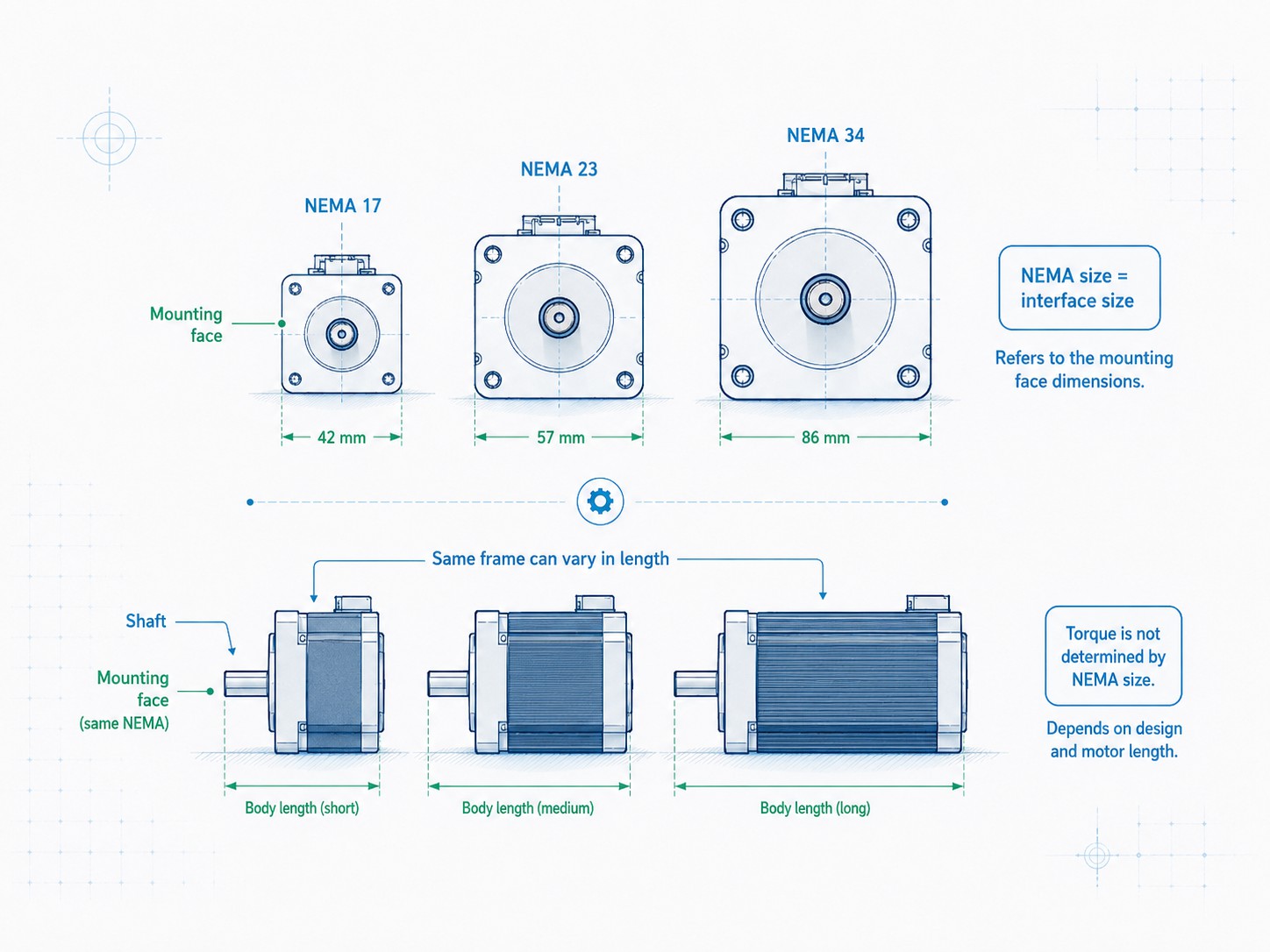
A NEMA number mainly identifies a standardized motor mounting frame. It does not directly specify torque, power, motor length, rated current, inductance, or high-speed performance.
That distinction matters whether you are selecting a compact NEMA 6 motor for an optical instrument, a NEMA 17 for a 3D printer, a NEMA 23 for a CNC router, a NEMA 34 for a heavier linear axis, or a NEMA 42/NEMA 51 motor for high-torque industrial machinery.
The publishes standards used throughout the electrical industry. Stepper and servo motion-control terminology and dimensions are associated with the NEMA ICS 16 family, described by the as covering rotational servo and stepper motors, their power requirements, feedback devices, and controls for motion and position control systems. In practical machine design, the NEMA frame designation gives engineers a common mechanical reference, but it is only the beginning of motor selection.
FRANK HU MOTOR offers a broad covering miniature and industrial frames, including NEMA 6, 8, 11, 14, 17, 23, 24, 34, 42, and 51. That wide range is useful because a machine designer can compare multiple mechanical envelopes instead of being limited to the three consumer-market sizes most often discussed online: NEMA 17, NEMA 23, and NEMA 34.
This guide explains the main NEMA stepper motor sizes from NEMA 6 through NEMA 51, how to read a stepper motor size chart, how frame dimensions relate to shafts and mounting, why two motors with the same NEMA number can perform very differently, and how to select a frame for CNC machines, automation equipment, robotics, 3D printers, laboratory devices, and heavy industrial systems.
Quick Answer: What Does a NEMA Stepper Motor Size Mean?
A NEMA frame number is a mechanical size designation. For common square-frame stepper motors, it is associated with the approximate face dimension of the motor family. For example, a NEMA 17 is commonly around 42 mm square, a NEMA 23 around 56-57 mm square, and a NEMA 34 around 85-86 mm square.
Manufacturers may use metricized dimensions that are close to the nominal inch-based family name. This is why a catalog may list NEMA 17 as 42 x 42 mm rather than exactly 1.7 in x 1.7 in, or NEMA 34 as 86 x 86 mm. , for example, lists common metric frame equivalents such as 42 mm for NEMA 17, 56.4 mm for NEMA 23, 60 mm for NEMA 24, and 85 mm for NEMA 34. likewise offers hybrid stepper families from very small flanges through NEMA 42-class 110 mm frames.
However, the NEMA number does not tell you the following:
-
motor body length;
-
holding torque;
-
running torque at 300, 600, or 1,000 rpm;
-
rated phase current;
-
phase resistance;
-
phase inductance;
-
rotor inertia;
-
winding temperature rise;
-
permissible radial or axial shaft load;
-
shaft diameter or shaft style in every product series;
-
whether the motor is 2-phase, 3-phase, or 5-phase;
-
whether it has an encoder, brake, gearbox, lead screw, hollow shaft, or integrated drive.
Treat the NEMA size as the mechanical doorway into the selection process, not as the final performance rating.
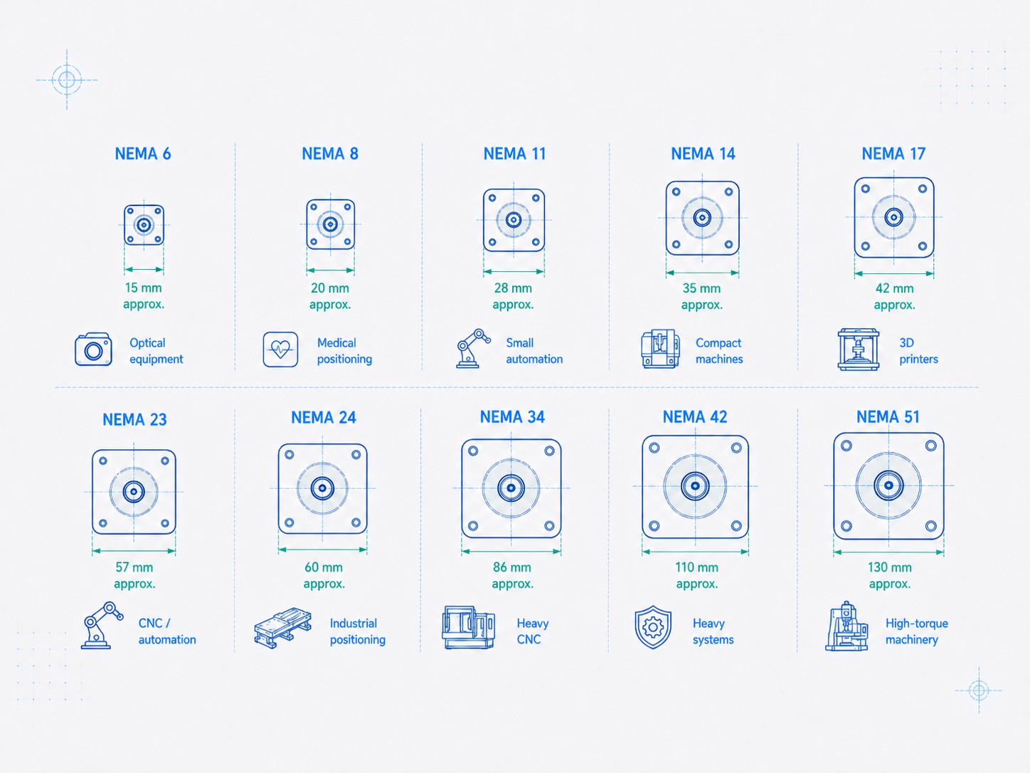
NEMA Stepper Motor Size Chart: NEMA 6 to NEMA 51
The following table is a practical engineering overview. The metric frame dimensions are common catalog values and may vary slightly by manufacturer or series. Shaft diameters are typical examples, not values guaranteed by the NEMA frame designation itself. Always verify the dimensional drawing for the exact part number before designing a motor mount, coupling, pulley, gearbox input, or shaft support.
| NEMA Size | Common Metric Face Size | Approx. Face Size in Inches | Typical Shaft Examples* | Typical Applications |
|---|---|---|---|---|
| NEMA 6 | 14 x 14 mm | 0.55 x 0.55 in | 4 mm | Optical devices, micro positioning, compact instruments |
| NEMA 8 | 20 x 20 mm | 0.79 x 0.79 in | 4 mm | Medical devices, miniature actuators, compact automation |
| NEMA 11 | 28 x 28 mm | 1.10 x 1.10 in | 5 mm | Small automation, laboratory equipment, compact linear stages |
| NEMA 14 | 35 x 35 mm | 1.38 x 1.38 in | 5 mm | Compact machines, feeders, small robots, light positioning |
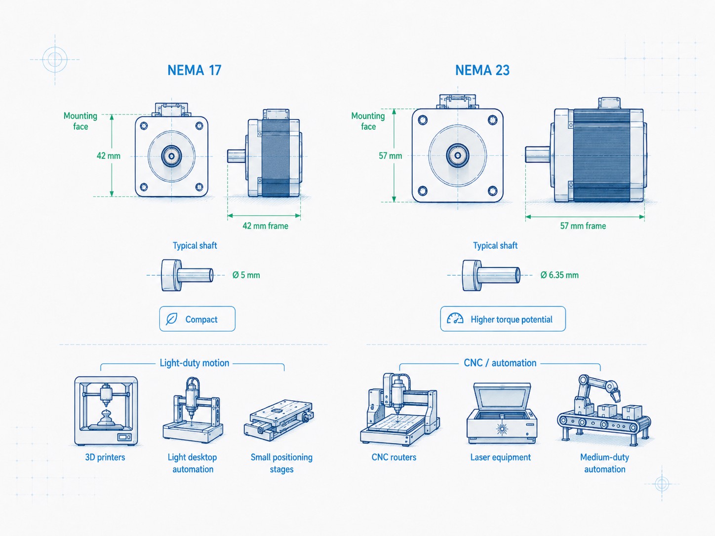
| NEMA 17 | 42 x 42 mm | 1.65 x 1.65 in | 5 mm | 3D printers, desktop CNC, light automation, small robotics |
| NEMA 23 | 57 x 57 mm | 2.24 x 2.24 in | 6.35 or 8 mm | CNC routers, packaging machines, industrial automation |
| NEMA 24 | 60 x 60 mm | 2.36 x 2.36 in | 8 mm | Higher-torque positioning, automation axes, compact machinery |
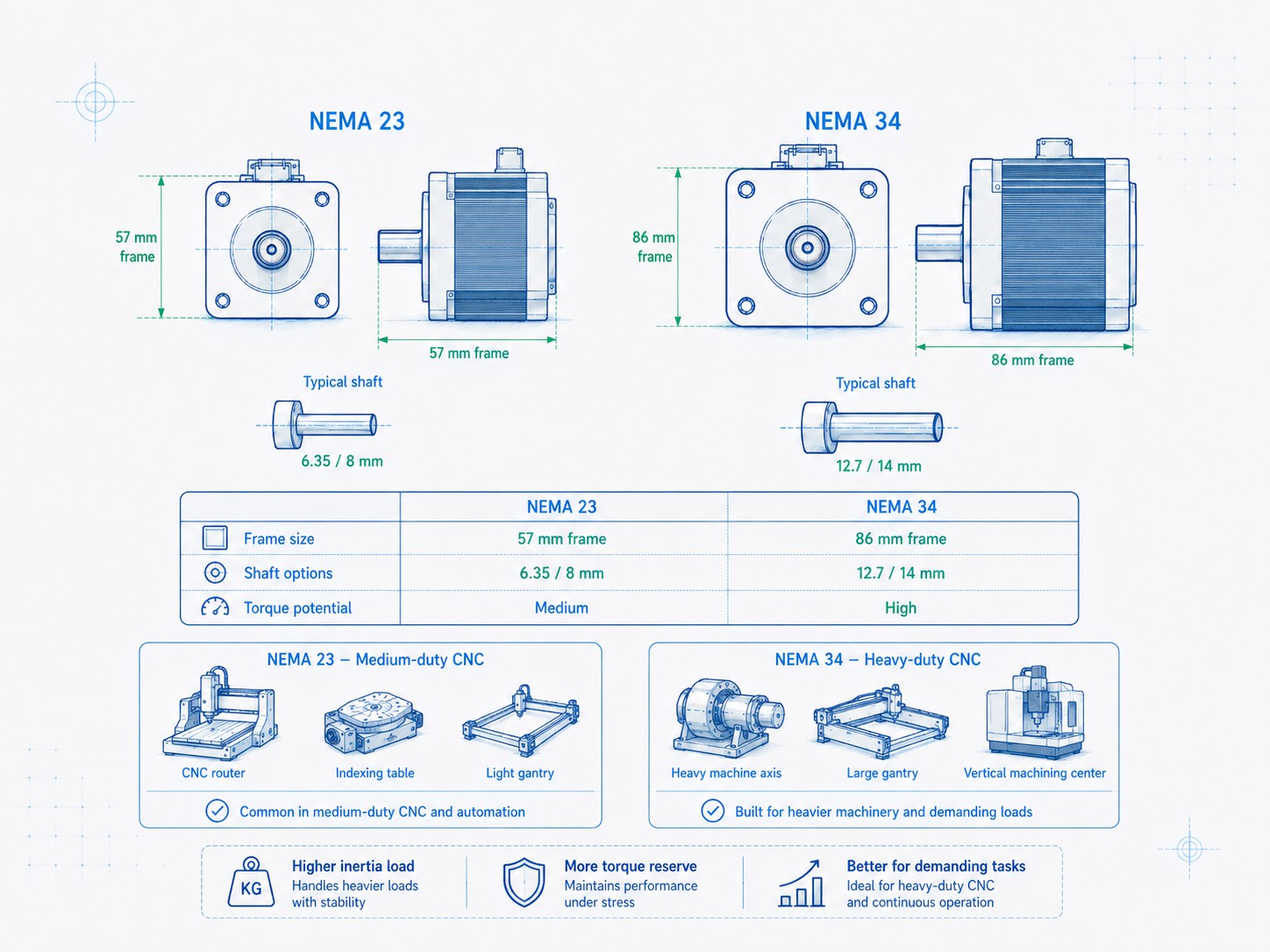
| NEMA 34 | 86 x 86 mm | 3.39 x 3.39 in | 12.7 or 14 mm | Heavy CNC, larger linear axes, indexing systems |
| NEMA 42 | 110 x 110 mm | 4.33 x 4.33 in | 19 mm common in larger industrial models | Heavy automation, large rotary tables, industrial mechanisms |
| NEMA 51 | 130 x 130 mm | 5.12 x 5.12 in | 19 mm or larger depending on design | High-torque machinery, large indexing systems, heavy-duty motion |
*Typical shaft examples are for quick comparison only. Shaft diameter, shaft length, flats, keyways, threads, rear shafts, and hollow-shaft geometry are product-specific.
The FRANK HU MOTOR catalog reflects this broad mechanical range. Its current category structure includes , , , , , , , , , and .
Why NEMA Size Does Not Equal Torque
This is the most common misunderstanding in online stepper motor selection.
A larger frame usually allows more copper, a larger rotor, greater magnetic area, larger bearings, and a larger thermal path. Therefore, moving from NEMA 17 to NEMA 23 or from NEMA 23 to NEMA 34 often increases the available torque range. But that is only a general trend. The NEMA number is not itself a torque specification.
Within the same frame, manufacturers can change motor performance by changing stack length, winding wire gauge, turn count, magnetic materials, rotor design, phase resistance, phase inductance, rated current, and the intended drive voltage. Two motors that bolt into the same mounting pattern can therefore behave very differently.
FRANK HU MOTOR's NEMA 34 catalog makes this easy to see. The same 86 x 86 mm face size is offered in multiple body lengths and torque levels.
| Example NEMA 34 Configuration | Face Size | Approx. Body Length | Holding Torque | Typical Shaft |
|---|---|---|---|---|
| Short NEMA 34 | 86 x 86 mm | 65 mm | about 3.5 Nm | 12.7 mm keyway |
| Medium NEMA 34 | 86 x 86 mm | 76 mm | about 4.5 Nm | 14 mm keyway |
| Longer NEMA 34 | 86 x 86 mm | 98 mm | about 7.0 Nm | 14 mm keyway |
| Longer/high-torque NEMA 34 | 86 x 86 mm | 115 mm | about 8.5 Nm | 14 mm keyway |
| High-torque NEMA 34 | 86 x 86 mm | 126 mm | about 10 Nm | 14 mm keyway |
| Long-stack NEMA 34 | 86 x 86 mm | 151 mm | about 12 Nm | 14 mm keyway |
The mounting face stays NEMA 34, but the motor length and holding torque change substantially. The 12 Nm example is listed in FRANK HU MOTOR's , while shorter versions share the same basic frame family.
This pattern also appears in smaller motors. NEMA 17 motors may use 20 mm, 22 mm, 28 mm, 34 mm, 40 mm, 48 mm, 60 mm, or other body lengths while retaining the same 42 x 42 mm mounting face. A short motor can be ideal for a low-inertia mechanism or compact enclosure even when a longer motor offers more holding torque.
The correct question is not, "How much torque does a NEMA 23 have?" The correct question is, "Which NEMA 23 motor, with which winding, body length, driver, supply voltage, and operating speed, provides enough dynamic torque for my load?"
Frame Size, Body Length, and Stack Length
Stepper motor body length is often the second mechanical dimension engineers should examine after the mounting face.
A longer hybrid stepper motor can generally accommodate a longer rotor/stator stack. More active magnetic length can increase holding torque, but it also tends to increase rotor inertia and motor mass. That tradeoff matters in high-acceleration axes.
Imagine two motors with the same NEMA 23 mounting flange:
-
Motor A is short and relatively low inertia.
-
Motor B is long and has higher holding torque but also a heavier rotor.
If the machine performs slow indexing against a high static load, Motor B may be clearly better. If the machine must reverse direction every 80 milliseconds, Motor A may accelerate more responsively, especially if its torque-to-inertia ratio and winding characteristics are better matched to the required speed.
This is why high holding torque alone is not always an advantage. In dynamic machinery, the motor must accelerate its own rotor as well as the external load.
For a more complete engineering workflow, see FRANK HU MOTOR's . That sizing process should be completed before treating frame size as the final decision.
NEMA 6 Stepper Motor: 14 mm Miniature Frame
NEMA 6 is at the miniature end of the hybrid stepper spectrum. A common metric face is about 14 x 14 mm. This class is useful when the design is constrained more by package volume and positioning resolution than by high mechanical output.
Typical applications include:
-
optical filter wheels;
-
small camera mechanisms;
-
miniature pumps and valves;
-
portable laboratory instruments;
-
compact medical devices;
-
micro positioning assemblies;
-
small lead-screw actuators.
A current FRANK HU MOTOR uses a 14 x 14 mm frame, 30 mm body length, 4 mm shaft, 0.3 A phase current, and approximately 0.005 Nm holding torque. These values describe that specific motor, not every NEMA 6 motor.
For designers, the main attraction is packaging. The challenge is that a very small rotor has limited torque and limited ability to absorb thermal losses. Mechanical friction, seal drag, screw efficiency, preload, and misalignment therefore consume a larger percentage of available torque than they would in a larger motor.
When evaluating NEMA 6, measure the real mechanical load carefully. A tiny coupling that is slightly misaligned can matter. So can a lead screw with excessive preload or a miniature linear bearing with unexpectedly high friction.
NEMA 8 Stepper Motor: 20 mm Compact Motion
NEMA 8 typically uses a 20 x 20 mm square frame. It is one of the most useful miniature sizes because it provides noticeably more mechanical capability than NEMA 6 while still fitting into compact devices.
Typical applications include:
-
medical automation;
-
compact dispensing systems;
-
small robotic mechanisms;
-
microscope stages;
-
miniature XY tables;
-
camera positioning;
-
compact linear actuators;
-
small valve control.
FRANK HU MOTOR's contains motors with multiple body lengths. This again demonstrates why the 20 mm frame alone does not define performance. A 20 x 20 mm motor may be a relatively short, low-torque unit or a longer motor with more magnetic stack.
A 4 mm shaft is common in this size, but engineers should not assume it. If the shaft directly carries a pulley or pinion, also check shaft length, flat geometry, allowable overhung load, and bearing arrangement.
For miniature belt drives, pulley inertia is often small, but belt tension can create radial bearing load. For miniature lead-screw systems, axial load and coupling alignment become more important. A motor that produces adequate torque can still have reduced bearing life if the mechanical load is poorly supported.
NEMA 11 Stepper Motor: 28 mm Frame
NEMA 11, commonly about 28 x 28 mm, is a useful bridge between miniature motion components and the more familiar NEMA 14/NEMA 17 classes.
Typical uses include:
-
laboratory automation;
-
compact sample handling;
-
small pick-and-place devices;
-
camera and sensor positioning;
-
miniature CNC mechanisms;
-
compact screw-driven stages;
-
light industrial actuators.
Compared with NEMA 8, a NEMA 11 motor gives the designer more room for torque without jumping directly to the 35 or 42 mm frame families. That can be valuable in equipment where every millimeter of enclosure width matters.
A 5 mm shaft is a common example for this frame, but the exact shaft must be confirmed from the motor drawing. The NEMA designation focuses primarily on the frame and mounting interface; shaft options can vary by supplier and by application.
NEMA 11 is also well suited to integrated mechanisms. An encoder can be added for closed-loop control, or a planetary gearbox can multiply output torque when low output speed is acceptable. A lead screw can convert rotary motion directly into linear motion and remove a separate coupling from the design.
NEMA 14 Stepper Motor: 35 mm Compact Industrial Frame
NEMA 14 is commonly around 35 x 35 mm. It is an important choice when a NEMA 17 is physically larger than necessary but miniature motors do not provide enough torque margin.
Typical applications include:
-
compact automation modules;
-
small feeders;
-
label and printing mechanisms;
-
optical equipment;
-
small collaborative robot accessories;
-
compact 3D printer mechanisms;
-
light linear stages;
-
laboratory devices.
FRANK HU MOTOR offers in multiple lengths and constructions. One conventional model uses a 35 x 35 mm frame and a 5 mm output shaft, while hollow-shaft and other special versions can have very different shaft geometry.
That distinction is important in procurement. If a drawing simply says "NEMA 14" and the buyer orders a random NEMA 14 motor, the mounting face may fit while the coupling does not. A complete motor specification should include the output shaft diameter, shaft length, shaft feature, connector or lead requirement, and any rear-shaft requirements.
NEMA 17 Stepper Motor: 42 mm and the Most Familiar Size
NEMA 17 is widely associated with 3D printers, desktop CNC systems, small automation equipment, robotics, and general-purpose positioning. A common metric frame is 42 x 42 mm.
Its popularity comes from a useful balance of cost, availability, torque, mass, and size. However, "NEMA 17" covers a wide performance range.
The includes motors with different step angles, phase currents, body lengths, torque ratings, shafts, and wiring configurations. This means there is no single correct NEMA 17 torque value.
Where NEMA 17 works well
NEMA 17 is often appropriate for:
-
FDM 3D printer X/Y axes;
-
extruders;
-
small Z axes;
-
desktop engraving machines;
-
light belt-driven stages;
-
camera sliders;
-
small robotic joints;
-
dosing and dispensing equipment;
-
instrument positioning.
Where NEMA 17 becomes marginal
It can become marginal when:
-
the axis uses a heavy lead screw or ball screw;
-
acceleration is high;
-
the gantry is heavy;
-
cutting forces are significant;
-
the motor must maintain torque at high rpm;
-
a large pulley is used;
-
the mechanism has high preload or friction;
-
the duty cycle causes excessive motor temperature.
A common mistake in 3D printers and small CNC machines is to upgrade to the longest available NEMA 17 solely for more holding torque. The heavier rotor may reduce acceleration performance. If the real problem is poor high-speed torque caused by a low-voltage driver or a high-inductance winding, simply adding motor length may not solve it.
NEMA 23 Stepper Motor: 57 mm for CNC and Automation
NEMA 23 is one of the most important industrial stepper sizes. A typical metric frame is approximately 57 x 57 mm, although references may show about 56.4 mm depending on the series.
NEMA 23 is widely used for:
-
CNC routers;
-
small milling and engraving systems;
-
automated assembly equipment;
-
packaging machines;
-
pick-and-place systems;
-
indexing tables;
-
medium linear stages;
-
robotic mechanisms;
-
laser cutting and marking equipment.
A common shaft size is 6.35 mm (1/4 inch), while 8 mm shafts are also common in some designs. FRANK HU MOTOR offers a , rated at 2.8 A per phase and 1.2 Nm holding torque. Other NEMA 23 motors use different body lengths, currents, inductances, and torque ratings.
NEMA 23 is often the first frame engineers consider for an industrial axis because it can produce useful torque without the mass and inertia of NEMA 34. It also matches a wide ecosystem of couplings, gearboxes, motor mounts, pulleys, and drives.
The selection still depends heavily on speed. A motor that produces 2 or 3 Nm at standstill may produce far less torque at the actual operating speed. CNC axes that require rapid traverse are especially sensitive to this issue.
NEMA 24 Stepper Motor: 60 mm Between NEMA 23 and NEMA 34
NEMA 24, often about 60 x 60 mm, is less famous than NEMA 23 and NEMA 34 but can be an excellent engineering compromise.
It is useful when a NEMA 23 solution is near its practical limit but a NEMA 34 motor is larger and heavier than desired. Depending on manufacturer, NEMA 24 can provide a slightly larger magnetic and thermal envelope while remaining closer to NEMA 23 in overall packaging.
Typical applications include:
-
industrial positioning axes;
-
compact packaging machines;
-
automation modules;
-
screw-driven actuators;
-
indexing systems;
-
moderate-load CNC mechanisms.
The uses a 60 mm frame family. As with every frame in this guide, the exact shaft and electrical characteristics depend on the individual model.
Do not assume that a NEMA 24 is simply "a slightly stronger NEMA 23." Compare actual torque-speed curves, rotor inertia, driver current, supply voltage, motor length, and mounting geometry.
NEMA 34 Stepper Motor Dimensions: 86 mm Heavy-Duty CNC Frame
NEMA 34 is one of the standard choices for high-torque stepper applications. FRANK HU MOTOR uses an 86 x 86 mm frame family, while other manufacturers may list about 85 mm or 86 mm as the metric equivalent.
Typical applications include:
-
heavier CNC routers;
-
plasma and laser machine axes;
-
large ball-screw stages;
-
industrial indexing mechanisms;
-
packaging equipment;
-
rotary tables;
-
heavy pick-and-place axes;
-
material handling systems.
Common shafts include 12.7 mm (1/2 inch) and 14 mm, often with a keyway. The includes both 12.7 mm and 14 mm shaft examples.
Why body length matters so much on NEMA 34
NEMA 34 clearly demonstrates the difference between frame size and motor performance. A short motor may provide several newton-meters of holding torque, while a long-stack motor in the same frame can exceed 10 Nm.
That does not mean the longest motor is always best. A longer NEMA 34 usually has:
-
more mass;
-
more rotor inertia;
-
greater current and/or different winding requirements;
-
potentially more heat;
-
a larger moment load on the motor mount;
-
a longer machine envelope.
In a vertical Z axis, the additional holding torque may be very useful. In a high-speed horizontal axis, lower inertia may be more important.
NEMA 34 and driver voltage
Large stepper motors are especially sensitive to electrical matching. Their windings can have substantial inductance. At higher step rates, current has less time to rise to its commanded value. A suitable current-regulated driver with sufficient DC bus voltage can improve high-speed current rise and therefore dynamic torque.
Applied Motion Products explains this effect in its technical note on , showing that higher drive voltage can keep the torque curve stronger to a higher speed when the motor and driver are used within their ratings.
This is one reason a NEMA 34 motor connected to an unsuitable low-voltage driver may perform worse than a properly driven NEMA 23 in a high-speed application.
NEMA 42 Stepper Motor: 110 mm Industrial Power
NEMA 42 is a large industrial stepper frame. FRANK HU MOTOR's uses approximately 110 x 110 mm face dimensions and includes both 2-phase and 3-phase configurations.
Typical applications include:
-
large CNC equipment;
-
industrial indexing systems;
-
heavy rotary mechanisms;
-
automated assembly machinery;
-
large linear stages;
-
material handling equipment;
-
heavy-duty positioning systems.
Larger NEMA 42 motors may use shafts around 19 mm, but again this is product-specific. At this scale, the engineering conversation should move beyond "Will it fit?" and include drive voltage, bus energy, stopping behavior, thermal performance, structural rigidity, shaft loading, bearing life, and machine safety.
NEMA 42 motors can provide very high holding torque, but high torque does not eliminate the stepper motor's fundamental speed-torque behavior. Torque still decreases as step rate rises. The motor also has substantial rotor inertia, which can limit acceleration.
For high-speed continuous motion, rapid acceleration, or very wide operating ranges, a servo system may become more attractive. FRANK HU MOTOR's explains the system-level tradeoffs.
NEMA 51 Stepper Motor: 130 mm for Very High Torque
NEMA 51 is a large frame used in high-torque industrial machinery. FRANK HU MOTOR's uses a 130 x 130 mm frame family.
One FRANK HU MOTOR 3-phase NEMA 51 example uses a 130 x 130 mm frame, approximately 312 mm body length, 6.8 A phase current, 19 mm shaft, and 60 Nm holding torque. That is an illustration of how far stepper technology can scale beyond the NEMA 17/NEMA 23 sizes commonly discussed in hobbyist applications.
Typical NEMA 51 applications may include:
-
large indexing mechanisms;
-
heavy industrial positioning;
-
high-load rotary systems;
-
machinery where low-speed holding torque is critical;
-
large automation fixtures;
-
specialized production equipment.
At this size, however, system engineering becomes essential. A 20+ kg motor and a high-energy drive system are not simply oversized versions of a desktop stepper axis. The machine structure, coupling, drive electronics, braking behavior, emergency-stop strategy, guarding, and thermal design must all be engineered accordingly.
A NEMA 51 stepper can be appropriate for high holding torque and controlled incremental motion, but there are applications where a servo motor, geared servo, or other drive technology offers better high-speed efficiency and closed-loop dynamic performance.
NEMA 17 vs NEMA 23: Which Should You Choose?
"NEMA 17 vs NEMA 23" is one of the most common stepper motor comparisons. The right answer depends on the axis, not on the popularity of the motor.
| Selection Factor | NEMA 17 | NEMA 23 |
|---|---|---|
| Typical face size | 42 x 42 mm | 57 x 57 mm |
| Typical shaft examples | 5 mm | 6.35 or 8 mm |
| Mass/inertia | Lower | Higher |
| Torque potential | Lower to moderate | Moderate to high |
| Common driver current | Generally lower | Generally higher |
| Best fit | 3D printers, light axes, compact mechanisms | CNC, automation, heavier linear axes |
| Acceleration advantage | Often better when load is light | Better when the extra torque is required |
| Packaging | Compact | Larger mount and enclosure required |
Choose NEMA 17 when the load is light, compact size matters, and the required speed/acceleration can be achieved with adequate torque margin.
Choose NEMA 23 when the axis has greater inertia, higher cutting/process force, larger screw diameter, higher preload, or a heavier gantry and the torque-speed curve shows a real need for the larger motor.
Do not upgrade from NEMA 17 to NEMA 23 just because a machine "feels underpowered." First check:
-
driver current setting;
-
supply voltage;
-
acceleration profile;
-
mechanical binding;
-
pulley or screw ratio;
-
winding inductance;
-
actual running torque at the required speed.
Many missed-step problems are system problems rather than frame-size problems.
NEMA 23 vs NEMA 34: Torque Is Not the Only Difference
The NEMA 23 vs NEMA 34 decision is common in CNC routers, plasma cutters, large 3D printers, and industrial automation.
| Selection Factor | NEMA 23 | NEMA 34 |
|---|---|---|
| Typical face size | 57 x 57 mm | 86 x 86 mm |
| Typical shaft examples | 6.35/8 mm | 12.7/14 mm |
| Rotor inertia | Moderate | Significantly higher in many models |
| Holding torque potential | Moderate | High to very high |
| Driver requirements | Medium current/voltage | Higher current and often higher bus voltage |
| Machine structure | Moderate mount stiffness | Stronger motor plate and coupling generally required |
| Typical use | CNC routers, automation | Heavy CNC, large screws, high-load positioning |
A NEMA 34 can solve a genuine torque shortage, but it also adds rotating inertia. If a NEMA 23 already provides sufficient dynamic torque, a NEMA 34 may reduce acceleration and increase cost without improving throughput.
For screw-driven machines, compare the complete reflected inertia and torque requirement. A ball screw can convert relatively modest motor torque into high linear force, while lead, diameter, efficiency, and acceleration determine the actual demand.
How to Read Stepper Motor Dimensions Correctly
A motor drawing contains more information than the square face size. Before releasing a machine design, check at least the following dimensions.
1. Frame width and height
This is the dimension most closely associated with the NEMA family. It determines the basic motor envelope and compatibility with the mounting plate.
2. Mounting-hole spacing
The motor may have four tapped or clearance mounting holes around the front face. Hole spacing and thread/diameter must match the machine plate. Never dimension a mounting plate from a product photo.
3. Pilot or boss diameter
Many stepper motors have a circular locating boss around the front bearing. This feature centers the motor accurately. If the machine design ignores the pilot and relies only on bolt clearance, shaft alignment can be worse.
4. Pilot height
The locating boss projects from the motor face. The mating plate must have appropriate clearance or a locating recess.
5. Shaft diameter
The shaft diameter determines coupling, pulley, pinion, and gearbox compatibility. It is not safe to infer shaft diameter solely from NEMA size.
6. Shaft length
A pulley may fit the shaft diameter but still be impossible to position if the shaft is too short. Conversely, an unnecessarily long shaft increases overhung leverage.
7. Shaft feature
Common shaft styles include:
-
round;
-
D-cut/flat;
-
keyway;
-
threaded;
-
dual shaft;
-
hollow shaft;
-
custom machined shaft.
The feature affects torque transmission and assembly method.
8. Body length
Body length changes torque capability, rotor inertia, machine envelope, and often motor mass. It must be checked separately from frame size.
9. Rear shaft, encoder, or brake length
A closed-loop stepper or brake-equipped motor can be significantly longer than the base motor. Leave space for connectors and cable bend radius as well.
Holding Torque vs Running Torque
Holding torque is one of the most advertised stepper motor specifications, but it is frequently misused.
Holding torque describes the torque available when the energized motor is stationary under specified conditions. A moving axis operates at nonzero speed, and the available torque falls as motor speed increases.
This happens because the motor winding has resistance and inductance. When the driver changes current from one phase state to the next, inductance resists rapid current change. At low speed, there is enough time for winding current to reach the commanded value. At high speed, there may not be.
Therefore, a motor rated at 4 Nm holding torque does not provide 4 Nm at every rpm.
For machine design, the relevant data is the torque-speed curve for the exact motor and driver conditions. Applied Motion's technical material on emphasizes the effect of drive conditions on the usable torque curve. Anaheim Automation also notes in its that the torque available from a stepper changes with speed and that the designer should consult individual speed-torque curves.
This is why two NEMA 23 motors can have similar holding torque but very different performance at 800 rpm.
Rated Current, Resistance, Inductance, and Drive Voltage
Mechanical frame size and electrical matching must be considered together.
Rated phase current
The motor's current rating tells you the phase current the winding is designed to handle under specified conditions. The stepper driver should be capable of regulating the correct current.
Do not choose a driver only by nominal motor voltage printed in a simple catalog. Modern stepper systems commonly use current-regulated chopper drives with a supply voltage substantially higher than the winding's DC resistance-times-current value.
Phase resistance
Resistance contributes to copper loss according to:
P = I^2 R
Higher current produces rapidly increasing copper heating. This is one reason current settings should follow the motor/driver manufacturer's method rather than being increased until the machine "feels stronger."
Phase inductance
Inductance affects how quickly current can rise and fall. For high-speed operation, excessive inductance can reduce dynamic torque because the current cannot build quickly enough during each electrical state.
Supply voltage
Within the driver's and motor system's ratings, a higher bus voltage can improve current rise at speed. It does not mean the motor phase current should exceed its rating. The driver regulates current while the higher available voltage helps overcome inductive effects.
This electrical interaction is one reason the same NEMA frame can produce very different results with different windings and drives.
FRANK HU MOTOR's includes low-voltage and higher-voltage stepper drive options for different motor sizes and applications. The motor, drive, and supply should be selected as one system.
Step Angle and Microstepping Do Not Change the NEMA Frame
Another source of confusion is step angle. NEMA size does not determine step angle.
Common hybrid stepper motors use:
-
1.8 degrees per full step, or 200 full steps per revolution;
-
0.9 degrees per full step, or 400 full steps per revolution;
-
other values in specialized 3-phase or 5-phase designs.
Microstepping subdivides the electrical full-step positions to create smoother motion and reduce low-speed vibration. It can improve command resolution and acoustic behavior, but it should not be interpreted as equivalent to mechanical positioning accuracy at every microstep.
A NEMA 17 can be 0.9-degree or 1.8-degree. A NEMA 23 can likewise have different winding and step configurations. Select step angle based on resolution, smoothness, speed, and driver capability - not on frame name.
Rotor Inertia: The Hidden Cost of a Bigger Motor
When designers oversize a stepper, they often focus on mass and price but overlook rotor inertia.
Acceleration torque follows the basic relationship:
T = J x alpha
where:
-
T is acceleration torque;
-
J is total rotational inertia reflected to the motor shaft;
-
alpha is angular acceleration.
A larger rotor increases the inertia the motor must accelerate even before external load inertia is considered.
Suppose a NEMA 34 motor has twice the available low-speed torque of a NEMA 23 but also much greater rotor inertia. If the axis performs rapid start-stop moves, the net improvement may be smaller than expected. In some machines, the smaller motor can produce faster cycle time because it accelerates its own rotor more easily.
This is especially relevant to:
-
pick-and-place systems;
-
scanning stages;
-
reciprocating cutters;
-
3D printer axes;
-
label feeders;
-
high-cycle indexing equipment.
For sizing, calculate or estimate load inertia, convert translational mass to reflected rotational inertia where applicable, include screw/pulley/coupling inertia, and compare the required acceleration torque with the motor's dynamic torque curve.
NEMA Frame Size and Linear Motion
Many stepper motors ultimately drive linear axes rather than rotary loads. The motor frame must therefore be selected together with the transmission.
Belt drive
A belt and pulley can provide high speed and simple mechanics. The pulley radius directly affects torque demand:
T = F x r
A larger pulley increases linear travel per revolution but also increases motor torque required for the same linear force.
Lead screw
A lead screw converts motor torque into linear force. Required torque depends on axial force, screw lead, efficiency, and preload/friction.
A higher lead increases travel per revolution but generally requires more motor torque for the same axial force. A smaller lead increases mechanical advantage but may require higher motor rpm to achieve the same linear speed.
Ball screw
Ball screws usually offer higher efficiency than sliding lead screws. They are widely used in CNC and precision automation. However, screw inertia, preload, nut friction, acceleration, and critical speed still matter.
FRANK HU MOTOR also offers , where the screw and motor are integrated into one assembly. For compact machines, this can eliminate a coupling and simplify alignment.
Open-Loop vs Closed-Loop Stepper in the Same NEMA Size
Adding an encoder does not fundamentally change the meaning of the NEMA frame. A closed-loop NEMA 23 motor may use essentially the same 57 mm mounting envelope as an open-loop NEMA 23, but the system behavior is different.
Open-loop stepper systems are attractive because they are simple and cost-effective. If correctly sized, they can deliver excellent repeatability without a position sensor.
Closed-loop stepper systems use encoder feedback to monitor motor position and improve fault detection or current control. They can be valuable when load variation is high or when missed-step detection is important.
However, an encoder does not make an undersized motor mechanically stronger. The motor still needs sufficient torque at the required speed.
For a detailed comparison, see .
When a Servo Motor Is Better Than a Larger Stepper
There is a point where increasing NEMA frame size is no longer the most efficient solution.
A larger stepper may be appropriate when the application needs:
-
strong holding torque;
-
predictable incremental motion;
-
moderate speed;
-
simple position control;
-
cost-effective industrial positioning.
A servo may be better when the application needs:
-
high continuous speed;
-
very rapid acceleration and deceleration;
-
wide speed range;
-
continuous high mechanical power;
-
sophisticated torque control;
-
high efficiency across a broad operating range;
-
closed-loop correction under changing load.
For example, if a NEMA 34 stepper must be replaced by a NEMA 42 only because high-speed torque is insufficient, investigate whether a servo system is a better architectural choice before increasing frame size again.
Gearboxes: More Torque Without a Larger NEMA Frame
A gearbox can allow a smaller motor to produce greater output torque at lower output speed.
If a gearbox has ratio i, ideal output torque would scale approximately with that ratio, but real output torque must include gearbox efficiency and the gearbox's own torque limit:
T_out approximately equals T_motor x i x eta
where eta is gearbox efficiency.
A planetary gearbox can be valuable for:
-
robotic joints;
-
rotary indexing;
-
valve actuation;
-
compact automation;
-
low-speed high-torque positioning.
But a gearbox also adds:
-
backlash;
-
cost;
-
length;
-
inertia;
-
efficiency loss;
-
additional bearings and life considerations.
Therefore, "smaller motor plus gearbox" and "larger direct-drive stepper" should be compared as complete systems.
FRANK HU MOTOR supports multiple gearbox combinations across NEMA sizes, including economy and precision planetary gear options. This can be useful for OEM designs that need to keep a specific mounting footprint while changing output speed and torque.
Thermal Design: Bigger Is Not Automatically Cooler
Motor temperature depends on electrical losses, duty cycle, mounting, ambient temperature, airflow, and motor construction.
A physically larger motor generally has more surface area and thermal mass, but it may also be driven at much higher current. A long motor operating near rated current can become hot even when it is mechanically oversized for the load.
Consider:
-
continuous vs intermittent duty;
-
phase current at standstill;
-
automatic idle-current reduction in the driver;
-
ambient temperature;
-
enclosure temperature;
-
heat conduction through the mounting plate;
-
airflow;
-
nearby heat sources;
-
cable and connector temperature ratings.
In applications that spend long periods holding position, idle-current reduction can significantly reduce heat if the application does not require full holding torque while stationary.
Temperature also affects surrounding components. A motor attached to a precision optical frame may create thermal drift. A motor mounted near plastic parts in a 3D printer may soften or distort them. A motor inside a sealed medical device may raise internal temperature even if the motor itself is within its insulation rating.
Mechanical Loads on the Shaft and Bearings
Stepper motor torque is only one part of mechanical capability. The shaft and bearings must survive radial and axial loads.
Examples of radial load include:
-
belt tension on a pulley;
-
gear mesh force;
-
overhung sprockets;
-
eccentric loads.
Examples of axial load include:
-
direct screw thrust;
-
helical gear force;
-
spring preload;
-
vertical mechanisms where thrust is transmitted through the motor shaft.
If a pulley is mounted far from the front bearing, the same belt force creates a larger bending moment. For high radial loads, support the driven shaft with external bearings rather than using the motor bearings as structural machine bearings.
For ball screws and high-thrust lead screws, use proper fixed/floating support bearings so the motor coupling transmits torque but not the full axial process load.
Application Guide by Machine Type
3D printers
NEMA 17 dominates conventional FDM printers because it offers a good size-to-torque balance. NEMA 14 or smaller motors can be useful for lightweight extruders and compact mechanisms. Larger NEMA 23 motors may appear in large-format printers, heavy Z axes, or pellet extruders.
Selection priorities:
-
low moving mass on X/Y axes;
-
smooth microstepping;
-
quiet operation;
-
sufficient torque at printing speed;
-
reasonable motor temperature;
-
compatible pulley and shaft dimensions.
Desktop CNC routers and engravers
NEMA 17 can work for very small machines, but NEMA 23 is more common when cutting loads and screw inertia increase. NEMA 34 is used in heavier routers or axes with larger ball screws and gantries.
Selection priorities:
-
cutting/process force;
-
rapid traverse speed;
-
acceleration;
-
ball screw or lead screw torque;
-
resonance;
-
frame rigidity;
-
driver voltage.
Laser cutters
Laser cutting axes can have relatively low process force but require rapid acceleration and smooth motion. Oversized motors can hurt acceleration because rotor inertia increases.
Selection priorities:
-
low inertia;
-
high-speed torque;
-
belt ratio;
-
smoothness;
-
gantry mass.
Pick-and-place equipment
Cycle time is often more important than holding torque. Motor inertia, acceleration, and settling behavior become critical.
Selection priorities:
-
torque-to-inertia ratio;
-
fast acceleration;
-
low vibration;
-
repeatability;
-
encoder feedback when missed-step detection is required.
Laboratory and medical automation
NEMA 6, 8, 11, and 14 can be especially valuable. Compact size, low noise, smooth operation, and integration flexibility may be more important than maximum torque.
Selection priorities:
-
package size;
-
temperature rise;
-
acoustic noise;
-
low-speed smoothness;
-
lead-screw integration;
-
cable routing;
-
repeatability.
Heavy CNC and industrial positioning
NEMA 34, 42, and 51 can provide high low-speed torque, but these systems need stronger mechanical design and higher-performance drives.
Selection priorities:
-
dynamic torque at actual rpm;
-
reflected inertia;
-
high-voltage drive compatibility;
-
motor/drive heating;
-
emergency stopping;
-
coupling torque rating;
-
shaft and bearing loads;
-
structural stiffness.
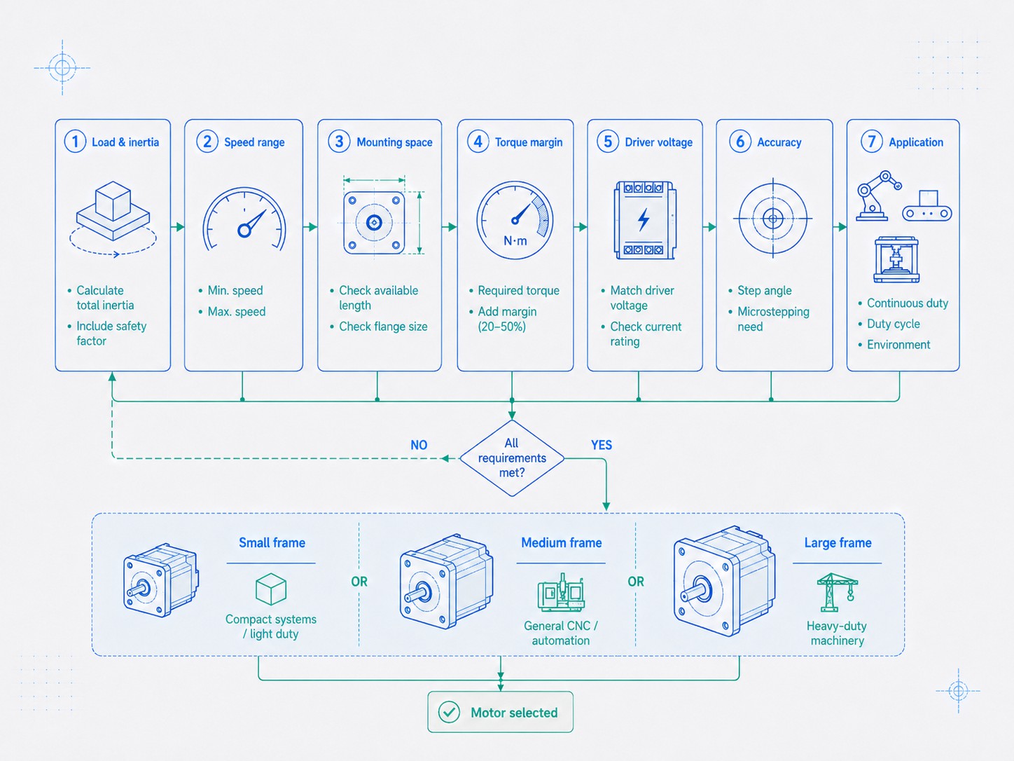
A Better Stepper Motor Selection Workflow
Instead of starting with "Which NEMA size do I need?", use the following engineering workflow.
Step 1: Define motion requirements
Document:
-
travel distance or rotation angle;
-
move time;
-
maximum speed;
-
acceleration/deceleration;
-
dwell time;
-
cycle rate;
-
positioning tolerance;
-
repeatability requirement.
Step 2: Calculate load torque and process force
Include:
-
gravity;
-
cutting force;
-
belt tension;
-
screw preload;
-
bearing friction;
-
seal drag;
-
gearbox losses;
-
safety margin.
Step 3: Calculate or estimate inertia
Include:
-
load mass;
-
pulley inertia;
-
screw inertia;
-
coupling inertia;
-
gearbox reflected inertia;
-
motor rotor inertia.
Step 4: Convert motion to motor speed
A motor that has enough torque at 200 rpm may fail at 1,000 rpm. Convert required linear velocity into screw or pulley rpm before comparing motors.
Step 5: Use torque-speed curves
This is the decisive step. Compare required torque with the available dynamic torque at the actual motor speed, using the proposed driver and supply conditions.
Step 6: Add engineering margin
Allow margin for:
-
friction changes;
-
lubricant aging;
-
temperature;
-
supply tolerance;
-
manufacturing variation;
-
load uncertainty;
-
machine wear.
Step 7: Select the smallest practical frame that meets the dynamic requirement
Once the motor-drive candidates are known, choose the frame that meets:
-
torque-speed requirement;
-
inertia target;
-
thermal requirement;
-
shaft load requirement;
-
mechanical envelope;
-
cost objective.
Step 8: Verify exact dimensions
Check the drawing for:
-
flange size;
-
hole spacing;
-
pilot diameter;
-
shaft diameter;
-
shaft length;
-
body length;
-
connector position;
-
rear encoder/brake clearance.
Step 9: Prototype under worst-case conditions
Test:
-
maximum load;
-
maximum speed;
-
aggressive acceleration;
-
hot ambient temperature;
-
long duty cycles;
-
vertical moves;
-
emergency stops;
-
supply-voltage limits.
A motor selection that works only on a cool bench with no process load is not yet a production design.
Procurement Checklist for OEM and Industrial Buyers
When requesting a quotation, do not send only "Need NEMA 23 stepper." That leaves too many engineering variables undefined.
A good RFQ should include:
| Parameter | Example Information to Provide |
|---|---|
| NEMA frame / maximum envelope | NEMA 23, max 57 x 57 x 76 mm |
| Step angle | 1.8 degrees |
| Holding torque target | 2.0 Nm minimum |
| Required running point | 1.0 Nm at 600 rpm |
| Rated phase current limit | 3.0 A max |
| Preferred inductance | Low-inductance winding for higher speed |
| Supply/driver | 48 VDC current-regulated drive |
| Shaft | 8 mm D-cut, 25 mm long |
| Rear shaft | Not required |
| Cable | 1 m, shielded if required |
| Connector | Customer-specified plug |
| Encoder | 1000 PPR if closed loop |
| Brake | 24 VDC holding brake if vertical axis |
| Environment | Indoor, dust level, temperature range |
| Quantity | Prototype, pilot lot, annual volume |
This information allows a motor supplier to recommend a winding and construction rather than merely matching a frame number.
FRANK HU MOTOR supports standard and customized motor configurations across stepper, closed-loop, geared, linear, hollow-shaft, and integrated motor families. For OEM projects, custom shafts, windings, cables, connectors, brakes, encoders, and gearbox combinations can be discussed against the actual machine requirements.
Common NEMA Stepper Motor Selection Mistakes
Mistake 1: Treating NEMA size as a torque rating
A NEMA 23 is not "1.2 Nm" by definition, and a NEMA 34 is not "8 Nm" by definition. Those are product-level specifications.
Mistake 2: Selecting from holding torque only
The machine runs at speed, so dynamic torque matters.
Mistake 3: Ignoring motor length
Two motors can have the same frame but very different depth, mass, inertia, and torque.
Mistake 4: Assuming all shafts are identical within a frame
Always check diameter, length, flat/keyway, and rear-shaft options.
Mistake 5: Using too little drive voltage for a high-inductance motor
The motor may have strong holding torque but weak high-speed performance.
Mistake 6: Oversizing the motor and hurting acceleration
A bigger rotor requires more torque to accelerate itself.
Mistake 7: Ignoring mechanical friction
Misalignment, tight bearings, over-preloaded screws, or belt tension can consume a large fraction of available torque.
Mistake 8: Ignoring thermal conditions
A stepper that works for five minutes may overheat in an enclosed 24/7 machine.
Mistake 9: Forgetting the driver
Motor and driver are a system. Current, voltage, microstep settings, and control method strongly affect performance.
Mistake 10: Designing the mount before selecting the exact part number
The nominal NEMA family is not enough for final production drawings.
Frequently Asked Questions
What is the most common NEMA stepper motor size?
NEMA 17 and NEMA 23 are among the most common general-purpose stepper sizes. NEMA 17 is especially common in 3D printers and compact equipment, while NEMA 23 is widely used in CNC and industrial automation. The best size is still application-specific.
Does a higher NEMA number always mean more torque?
Usually the potential torque range increases with a larger frame, but the NEMA number itself is not a torque rating. A long, optimized smaller-frame motor can overlap the torque range of a short larger-frame motor. Always compare the exact data sheet and torque-speed curve.
What are standard NEMA 17 dimensions?
A typical NEMA 17 stepper motor has a square front face around 42 x 42 mm. Body length varies widely by model. A 5 mm shaft is common, but shaft dimensions are not guaranteed solely by the NEMA designation.
What are NEMA 23 stepper motor dimensions?
A typical NEMA 23 frame is about 56-57 mm square. FRANK HU MOTOR uses a 57 x 57 mm frame family. Body length, shaft diameter, pilot, and electrical characteristics vary by motor.
What are NEMA 34 stepper motor dimensions?
A typical NEMA 34 frame is about 85-86 mm square. FRANK HU MOTOR uses 86 x 86 mm frames, with multiple body lengths. Common shaft examples include 12.7 mm and 14 mm keyway shafts.
Is NEMA 24 the same as NEMA 23?
No. They are different frame families. NEMA 24 is commonly around 60 mm square, compared with approximately 56-57 mm for NEMA 23. Some product series may share related mounting conventions or accessories, but designers should verify the exact drawing rather than assuming interchangeability.
Is NEMA 42 much stronger than NEMA 34?
It has a much larger mechanical envelope and can support higher-torque motor designs, but actual performance depends on body length, winding, phase count, current, voltage, and speed. A NEMA 42 should be selected from its torque-speed curve, not simply because it is larger.
Can I replace a NEMA 17 with any other NEMA 17?
Not automatically. The mounting face may be compatible, but you must also compare body length, shaft, connector, rated current, inductance, step angle, holding torque, rotor inertia, and driver compatibility.
Can I use a NEMA 34 motor with a driver designed for NEMA 23?
Only if the driver's current, voltage, control mode, and other electrical ratings match the exact motor. "NEMA 23 driver" and "NEMA 34 driver" are marketing shorthand, not complete electrical specifications.
What shaft diameter does a NEMA 23 use?
6.35 mm and 8 mm are common examples, but shaft diameter is not determined solely by the frame designation. Verify the exact product drawing.
What shaft diameter does a NEMA 34 use?
12.7 mm and 14 mm are common examples in industrial stepper motors. Keyways are common at this size. Always confirm the exact model.
Which NEMA size is best for a CNC router?
Small desktop routers may use NEMA 17, many conventional routers use NEMA 23, and heavier machines may use NEMA 34. Very large systems can use NEMA 42 or servo motors. The correct choice depends on screw/pulley ratio, gantry mass, cutting force, acceleration, rapid speed, driver voltage, and torque-speed curve.
Which NEMA size is best for a 3D printer?
NEMA 17 is the standard choice for many FDM printers. NEMA 14 or smaller can reduce moving mass in compact mechanisms, while NEMA 23 may be justified in large-format systems or heavy Z axes. Bigger is not automatically better because rotor mass affects acceleration.
Does microstepping increase torque?
Microstepping is mainly used for smoother motion, reduced vibration, and finer command increments. It should not be treated as a method for multiplying the motor's available torque.
Should I choose a closed-loop stepper instead?
Closed-loop control can provide encoder feedback, fault detection, and improved behavior under load variation. It does not remove the need for correct motor sizing. If the motor cannot produce enough torque at the required speed, feedback cannot create missing mechanical capacity.
Final Selection Guide
For quick preliminary screening:
-
NEMA 6 / NEMA 8: miniature mechanisms, optical devices, medical/lab equipment, micro linear positioning;
-
NEMA 11 / NEMA 14: compact industrial mechanisms where space matters but more torque is required;
-
NEMA 17: 3D printers, light automation, desktop CNC, small robotics;
-
NEMA 23: mainstream CNC routers, packaging equipment, automation axes, medium-load positioning;
-
NEMA 24: a useful intermediate 60 mm frame when NEMA 23 is close to its limit but NEMA 34 is unnecessarily large;
-
NEMA 34: heavy CNC, larger ball-screw axes, industrial indexing and higher-load mechanisms;
-
NEMA 42: heavy industrial motion requiring large low-speed torque;
-
NEMA 51: specialized very-high-torque machinery and large positioning systems.
Then move beyond frame size. Confirm the exact motor body length, holding torque, torque-speed curve, phase current, resistance, inductance, driver voltage, rotor inertia, shaft dimensions, thermal limits, and mechanical load capability.
The best stepper motor is not the largest motor that fits. It is the smallest practical motor-drive combination that meets the required dynamic torque, speed, acceleration, thermal, mechanical, and reliability margins of the machine.
For projects where several frames could work, compare the and use the detailed