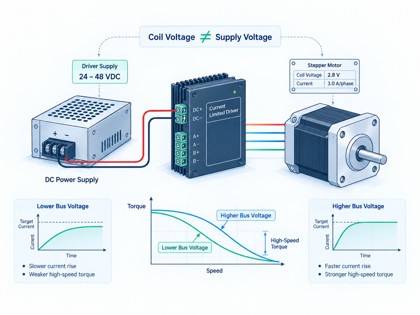
This is why stepper motor driver selection becomes a purchasing decision very close to the point of sale. Once a machine builder has already selected a NEMA 17, NEMA 23, NEMA 34 or other hybrid stepper motor, the next items are normally the driver, power supply, cables and controller. Getting those four items right determines whether the axis delivers the expected speed and torque in the real machine.
The most important rule is simple:
Do not choose a stepper driver by motor nameplate voltage. Choose it by motor phase current, winding inductance, required speed, supply-voltage range, control interface, microstep requirement and thermal margin.
A modern chopper driver intentionally uses a DC bus voltage that is often many times higher than the motor's simple winding voltage. It then regulates phase current electronically. This arrangement allows current to build more quickly in the inductive windings, which is critical as step frequency rises. Leadshine's digital stepper-drive installation guidance makes the same engineering distinction: supply voltage primarily influences high-speed performance, while drive output current primarily influences motor torque, particularly at low speed. Texas Instruments likewise describes winding-current rise as a function of DC bus voltage, winding inductance and back EMF in its stepper current-regulation documentation.
For buyers who already know their motor and want a practical driver shortlist, the includes low-voltage compact drives, 20-50 V class drives, 20-80 V class drives, closed-loop drives and higher-voltage products. One example is the , listed for 2-phase stepper motors with a 24-110 VDC / 18-80 VAC input range, 2.4-7.2 A output-current range, 5/24 V control signals and up to 200 kHz pulse input. Those numbers make it suitable for a very different class of application than a compact 24 V, 2 A driver.
Quick Selection Table: What Must Match First?
The table below is a fast first filter. Passing this table does not replace checking a torque-speed curve, but it can eliminate obviously incompatible combinations before purchase.
| Selection item | What to read from the motor | What to verify on the driver | Why it matters |
|---|---|---|---|
| Phase count | 2-phase, 3-phase, 5-phase | Driver must support the same motor topology | A 2-phase driver cannot correctly drive a 3-phase motor |
| Rated phase current | A/phase, and whether the value is bipolar, unipolar, RMS or another convention | Adjustable output-current range and current convention | Too little current reduces torque; too much increases heating |
| Winding inductance | mH/phase | Appropriate bus-voltage capability | Higher inductance generally needs more voltage to maintain current at speed |
| Winding resistance | ohm/phase | Current regulation and thermal setting | Helps explain winding voltage and copper loss |
| Required speed | rpm or linear speed converted to rpm | Driver voltage, pulse-frequency limit and torque-speed data | High-speed torque may collapse even when holding torque looks sufficient |
| Step angle | Commonly 1.8°, 0.9°, 1.2° for some 3-phase motors | Available microstep settings | Determines base steps/revolution and pulse demand |
| Lead configuration | 4, 6 or 8 leads | Wiring method supported | Series/parallel/half-coil wiring changes current and inductance |
| Control signal | Required by controller | PUL/DIR, CW/CCW, 5 V, 24 V, differential, open collector, etc. | Signal mismatch can cause no motion or intermittent motion |
| Feedback | None or encoder | Open-loop or closed-loop driver | Encoder motors require a compatible feedback interface for closed-loop use |
| Environment | Ambient temperature, cabinet, dust, airflow | Driver temperature rating and cooling method | Current capability is often thermally limited |
| Safety | Bus voltage and machine category | Grounding, fuse, isolation and applicable standards | 72 VDC, 110 VDC and mains-input systems need much more careful installation |
A useful companion article is , because the driver cannot compensate for a motor that is fundamentally undersized for the load. The is also important because a NEMA frame number identifies a mounting size, not a universal current or torque rating.
For example, the includes motors with substantially different rated currents and holding torques inside the same 57 mm frame family. A NEMA 23 label alone therefore cannot tell you whether the correct driver should be a 2.2 A compact unit, a 4.2 A digital drive or something larger. The same principle becomes even more important with long-stack NEMA 34 motors.
The Seven Driver-Selection Myths That Cause Most Problems
Myth 1: The motor nameplate voltage is the required driver power-supply voltage
This is one of the most common mistakes in stepper systems.
A motor data sheet may show a phase current and phase resistance. If a winding is rated 2.8 A and has 1.1 ohm resistance, simple Ohm's law gives a winding voltage of approximately:
V = I x R = 2.8 A x 1.1 ohm = 3.08 V
That does not mean a modern stepper system should use a 3.08 V power supply.
At standstill, a chopper driver rapidly switches the much higher DC bus voltage and limits the winding current to the configured value. At speed, the higher available bus voltage helps force current into the winding quickly despite inductance and back EMF. This is why a motor with a winding voltage of only a few volts may be operated from a 24 V, 36 V, 48 V, 72 V or higher bus when the motor, driver and application are designed for it.
Texas Instruments explains this behavior in its : winding current rises at a rate that depends on DC voltage, winding inductance and back EMF, and the driver then chops the current when the programmed threshold is reached. In other words, the power-supply voltage is a dynamic-performance parameter, while the driver enforces the winding-current limit.
Myth 2: More voltage always means more low-speed torque
At low speed, once the driver can establish the commanded phase current correctly, increasing bus voltage usually does not produce a proportional increase in holding torque. Low-speed and holding torque are much more closely related to phase current, motor construction and magnetic saturation.
Higher voltage becomes especially valuable as speed rises because each electrical state is shorter. The winding has less time to reach its target current before the next step. Higher bus voltage increases the rate of current rise, helping preserve useful torque farther into the speed range.
However, excessive voltage can increase switching stress, acoustic noise, low-speed vibration and regenerative overvoltage risk. It can also destroy the driver if the maximum rating is exceeded. Leadshine recommends leaving practical headroom below a driver's absolute input limit rather than designing continuously at the maximum boundary.
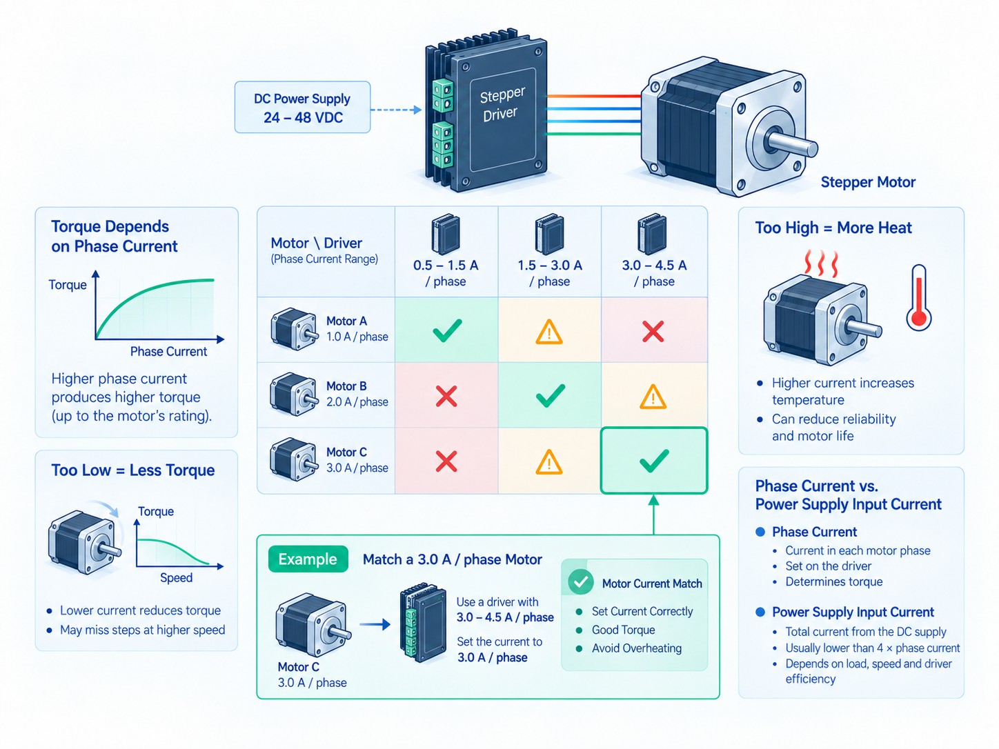
Myth 3: Phase current and power-supply input current are the same thing
They are not.
A chopper driver converts energy from the DC bus into controlled current in the motor windings. Energy is recirculated during PWM chopping, and the average current drawn from the power supply depends on bus voltage, motor speed, torque demand, winding current, driver efficiency, duty cycle and deceleration behavior.
Therefore, a 4.2 A/phase motor does not automatically require a 4.2 A DC power supply for each axis, and two energized phases do not mean the supply must deliver 8.4 A continuously.
Leadshine's gives a useful historical example for unregulated supplies: the average supply current can be substantially lower than motor phase current because the driver draws from the supply during only part of the PWM cycle. It cites 50-70% of motor current as a typical sizing range for certain unregulated arrangements and gives the example of two 3 A motors being supplied by a 4 A source. That is a useful engineering reference, but it should not be treated as a universal formula for every modern switching power supply, multi-axis duty cycle or regenerative machine.
For current industrial design, size the power supply from the actual axis duty, simultaneous acceleration, driver efficiency, peak demand and the power supply manufacturer's overload behavior. If several axes share one supply, also evaluate the worst coordinated move rather than assuming all axes operate independently.
Myth 4: A driver current number can be compared directly without checking peak versus RMS
Driver manufacturers use different current conventions. One model may list peak current, another RMS current, and another a DIP-switch value defined by its own internal waveform convention.
For an ideal sinusoidal current waveform:
I(RMS) = I(peak) / sqrt(2)
So 5.66 A peak corresponds to approximately 4.0 A RMS in that idealized convention. But you must not apply this conversion blindly to every product label because driver manufacturers may define their current table differently.
This matters commercially because many NEMA 23 and NEMA 34 motors are sold with familiar values such as 2.8 A, 4.2 A or 6.0 A per phase. A driver advertised as “5.6 A” could be either a comfortable match or an undersized choice depending on whether that number is peak, RMS or another specified value.
The correct workflow is:
-
Read the motor's rated current and wiring configuration.
-
Read the driver's current-setting table.
-
Identify whether the driver table is peak or RMS.
-
Use the driver's own conversion guidance.
-
Run a thermal test under the real duty cycle.
Myth 5: More microsteps mean the same proportional improvement in mechanical accuracy
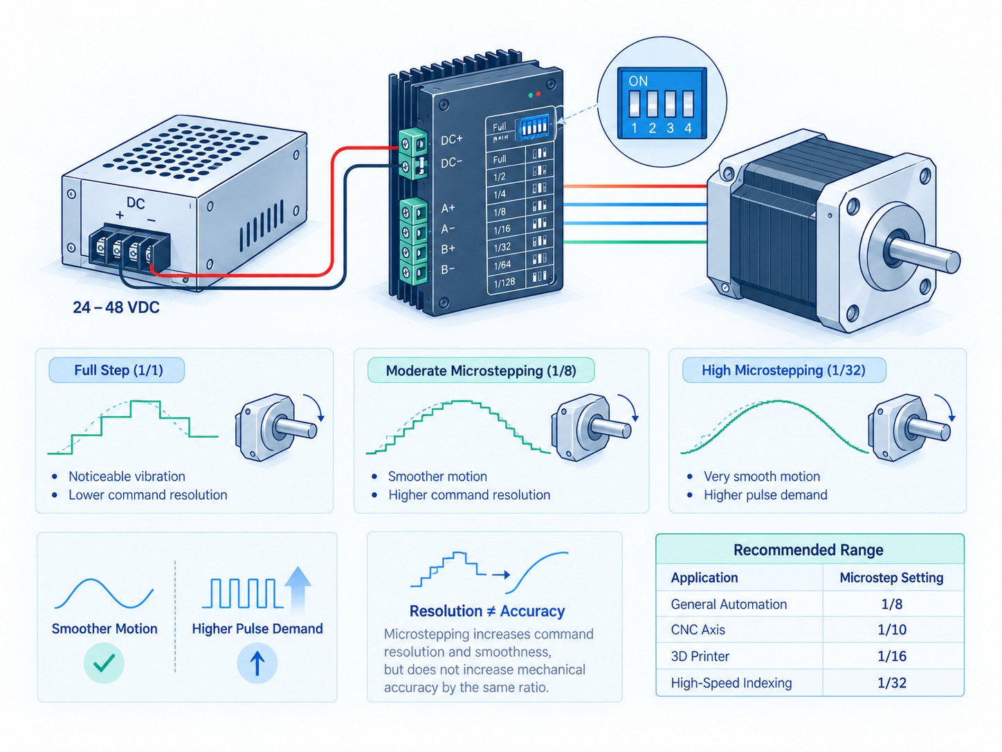
Microstepping improves command resolution and generally improves smoothness, vibration and noise. It does not guarantee that the rotor physically moves by a perfectly equal fraction of the full-step angle under load.
Analog Devices explains this clearly in : microstepping increases the number of commanded positions, but motor construction tolerances, load, detent torque and current-regulation accuracy still limit true position accuracy. The article also discusses the reduction in incremental torque as microstep size becomes smaller.
Oriental Motor publishes a similar distinction in its , including a full-step stop-position accuracy figure of ±0.05° for that product family and discussion of how current-waveform quality affects microstep stopping accuracy.
The practical implication is important: 1/16 microstepping does not automatically make a 1.8° motor sixteen times more mechanically accurate. It gives 16 times more command increments per full step.
Myth 6: If the motor stays cool, a high current setting is always better
Higher phase current usually increases available low-speed torque until magnetic saturation and thermal limits reduce the benefit. But copper loss rises approximately with the square of current:
P(copper) = I²R
If current is increased by 20%, copper loss rises by approximately 44% before considering other losses. That is why aggressive current settings can create a large temperature increase for a relatively small torque benefit near saturation.
Many digital drivers reduce current automatically at standstill. Leadshine documents one common implementation where reducing idle current to 60% theoretically reduces winding copper heating to 36% of the full-current value because of the I² relationship. The exact idle-current percentage varies by driver, but the principle is broadly useful.
Myth 7: If the motor has enough holding torque, it has enough running torque
Holding torque is measured at zero speed. It is not a substitute for a torque-speed curve.
As speed rises, winding inductance and back EMF reduce current tracking. Torque falls, sometimes rapidly. A motor that appears enormously oversized from holding torque may still stall during a high-speed rapid move if the driver voltage is too low or the winding inductance is too high.
This is why a driver can be the difference between a machine that reaches 1,000 rpm reliably and one that loses steps at 500 rpm even when the motor is identical.
Stepper Driver Voltage: How to Choose the Bus Voltage
The most useful way to think about bus voltage is not “what voltage does the motor need?” but rather:
How much voltage does the driver need to make the commanded phase current rise fast enough at the required motor speed, without exceeding the driver's electrical and thermal limits?
For a winding approximated as an R-L circuit, current rise is governed by the electrical time constant:
tau = L / R
where L is winding inductance and R is winding resistance. A high-inductance winding changes current more slowly than a low-inductance winding. As motor speed increases, the driver has less time per electrical step to establish the required current. At the same time, back EMF rises and opposes the applied voltage.
This is why two motors with the same holding torque can behave very differently at 1,000 rpm.
Voltage should be high enough, not simply as high as possible
A good engineering target is the lowest bus voltage that still provides the required torque margin throughout the speed profile. That approach usually improves reliability, reduces unnecessary switching stress and helps control heat.
Leadshine's installation guidance suggests keeping margin from the driver's upper and lower input limits to allow for power-supply tolerance and back EMF during deceleration. That is especially important in a vertical axis, high-inertia gantry or fast deceleration where energy can return to the DC bus.
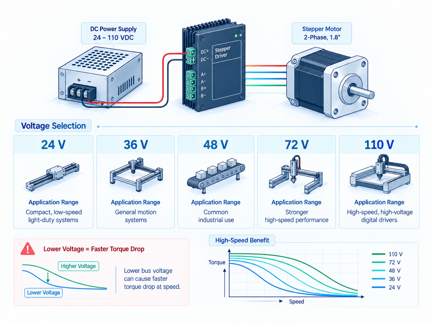
24 V, 36 V, 48 V, 72 V and 110 V: Typical Use Cases
The table below is not a universal motor-to-voltage chart. It is a practical application map for modern chopper-driven stepper systems. Always verify the exact driver's allowable input and the motor's torque-speed data.
| Bus level | Typical applications | Common motor/axis class | Strengths | Main cautions |
|---|---|---|---|---|
| 24 VDC | 3D printers, small laboratory automation, valves, feeders, compact XY stages, low-speed NEMA 17/NEMA 23 axes | Low to moderate current, low-speed or short-travel axes | Safe and widely available industrial control rail; low switching stress; easy PLC integration | High-speed torque may fall early, especially with higher-inductance motors |
| 36 VDC | Medium-speed NEMA 17/23 systems, desktop CNC, engraving, packaging mechanisms | Moderate current and moderate inertia | Good compromise between 24 V simplicity and better speed performance | Must confirm driver rating; less common as a plant-wide control rail than 24/48 V |
| 48 VDC | CNC routers, laser cutters, larger 3D printers, pick-and-place axes, NEMA 23/24 and selected NEMA 34 systems | Medium/high current, higher rapid speed | Strong practical balance of speed, torque and readily available switching supplies | Regeneration and cabinet thermal design become more important |
| 72 VDC class | Heavy CNC router axes, plasma tables, long ball-screw axes, higher-speed NEMA 34 systems | Larger motors or higher-inductance windings | Better high-speed current tracking and stronger torque at elevated rpm | Higher electrical hazard; requires driver headroom, careful deceleration and protection design |
| 110 VDC class | Heavy NEMA 34 or specialty industrial stepper axes where high bus voltage is justified by the torque-speed requirement | High-current, high-inductance or demanding CNC/automation axes | Extends useful high-speed torque when the driver and motor are designed for it | Hazardous voltage; stricter insulation, enclosure, fuse, grounding and service procedures; do not operate near driver max without margin |
The is useful here because it spans several of these bus levels in one high-voltage driver family. The page lists 24-110 VDC / 18-80 VAC in the title and key features. As with any industrial product, confirm the latest manual and label before final cabinet release because online specification tables can be revised and because maximum ratings are not always the recommended operating point.
FRANK HU MOTOR also offers in common 24 V, 36 V and 48 V classes, which makes it possible to purchase the motor, driver and power source as a matched motion package rather than treating them as unrelated components.
Stepper Driver Current Setting: The Torque Control You Must Get Right
If supply voltage largely determines how well current can be maintained at speed, phase-current setting determines how strongly the motor is magnetized and therefore strongly affects available torque, especially at low speed.
The safest starting rule for a common 4-wire bipolar motor is:
Set the driver to the motor manufacturer's rated phase current using the same current convention, then reduce or increase only when the motor and driver manuals support that adjustment and a thermal test confirms acceptable temperature.
Why too much current creates heat quickly
Suppose a winding has 0.8 ohm resistance.
At 3.0 A:
P = I²R = 3.0² x 0.8 = 7.2 W per energized winding equivalent
At 3.6 A, only 20% more current:
P = 3.6² x 0.8 = 10.37 W
That is approximately 44% more copper loss.
The real driver waveform and two-phase excitation make total motor heating more complex than this simplified single-winding illustration, but the square-law relationship explains why “just one current switch higher” can make a motor substantially hotter.
Why too little current causes lost torque
If you set a 4.2 A motor to 2.5 A, the motor may still turn smoothly at no load. That can create a false sense that the system is correctly configured. Under acceleration, cutting load, vertical lifting force or belt tension, the torque reserve may disappear and the motor can lose synchronism.
This is one reason commissioning should include the real acceleration, maximum speed and worst load, not only a slow jog test.
Lead count changes the correct current setting
A 4-wire motor has one basic bipolar connection. Six- and eight-lead motors are more flexible.
A six-lead motor can often be used in half-coil or full-coil configuration. An eight-lead motor can commonly be wired series or parallel. These choices change resistance, inductance and required current.
Leadshine's installation manual gives typical examples:
-
Half-coil and parallel configurations provide lower inductance and are generally better for higher-speed performance.
-
Series/full-coil configurations increase inductance and favor lower-speed use.
-
The required driver current must be adjusted according to the selected wiring method rather than copied from one arbitrary motor label value.
For an industrial buyer, this means the question “What driver do I need for this 8-wire NEMA 34?” is incomplete until the intended series or parallel wiring is known.
Peak Current vs RMS Current: A Practical Purchasing Example
Consider a motor data sheet that specifies 4.2 A per phase. Now compare two hypothetical drivers:
| Driver | Published current range | Current convention | Correct conclusion |
|---|---|---|---|
| Driver A | 1.0-4.2 A | RMS | 4.2 A setting may directly match the motor rating if the motor current is also RMS-equivalent |
| Driver B | 1.4-5.9 A | Peak | 4.2 A peak may be too low; the correct switch may be closer to the manufacturer's stated peak equivalent |
| Driver C | 2.4-7.2 A | “Output current” with separate RMS note | Do not guess; use the product manual/current table |
The important lesson is that matching the printed amp number is not enough. This is especially important when comparing products from different brands or when replacing an older drive with a newer digital model.
Stepper Motor Power Supply Selection
A reliable stepper power supply must satisfy four different requirements:
-
Correct bus voltage for the driver and speed target.
-
Adequate continuous and peak power for the axes.
-
Enough margin for supply tolerance and regenerative voltage rise.
-
Suitable industrial protection, cooling and grounding.
Do not size the supply only by adding motor phase currents
For a multi-axis machine, adding every motor's phase current and buying a supply with the same ampere total is usually not an accurate power calculation. The driver is a switching converter, and phase current is not equal to DC input current.
A more useful planning method is to estimate electrical input power from the real duty cycle and then validate against the driver manufacturer's guidance. If measured data are available, use them.
For example, suppose a 48 V three-axis CNC uses three NEMA 23 motors. During normal cutting, each axis may require much less than its configured phase-current maximum. During a coordinated rapid acceleration, however, two or three axes may demand significantly more power at the same time. The power supply should tolerate that transient without entering current limit and collapsing the bus.
Regulated switching supply versus unregulated supply
Modern industrial cabinets commonly use regulated switching power supplies because they are compact, efficient and widely available. Older stepper guidance often favors unregulated linear supplies because their large capacitors can tolerate short surge currents and absorb some returned energy.
Neither type is automatically superior in every machine. With a regulated switching supply, check:
-
overload mode: constant current, hiccup, foldback or shutdown;
-
output capacitance and remote wiring inductance;
-
whether reverse energy can be absorbed;
-
allowable parallel connection;
-
derating at cabinet temperature;
-
line input range;
-
conducted/radiated EMC behavior;
-
protective earth requirements.
If a switching supply enters hiccup mode when a gantry accelerates, the symptom may look like a motor or driver fault even though the actual problem is power-source behavior.
Shared supply for multiple drivers
Multiple drivers can share one DC supply when the supply has adequate capacity. Connect each drive back to the common distribution point rather than daisy-chaining power through one drive to the next. This star-like distribution reduces cross-coupled voltage drop and interference.
Leadshine explicitly recommends separate connections from each drive to the shared supply instead of daisy-chaining the drive power terminals.
Regenerative energy during deceleration
A moving machine contains kinetic energy. During deceleration, the motor can act as a generator and return energy to the DC bus. The effect is especially important with:
-
heavy gantries;
-
long deceleration from high speed;
-
vertical axes descending under gravity;
-
large pulleys or flywheels;
-
high-inertia rotary tables.
If the power supply cannot absorb returned energy, bus voltage rises. The result may be an overvoltage alarm or, in the worst case, driver damage.
Solutions depend on the drive and machine architecture and may include slower deceleration, additional bus capacitance, a braking resistor, a clamp circuit, a supply designed to absorb reverse energy or a different drive topology.
AC vs DC Stepper Driver: Which Is Better?
“AC vs DC stepper driver” usually refers to the driver's input power source, not to a different kind of stepper motor. Many industrial stepper motors are still driven by regulated phase current from an internal DC bus; an AC-input driver simply rectifies and conditions the AC internally.
DC-input driver advantages
DC-input drives are usually the best choice when the machine already has a 24 V, 36 V, 48 V or other DC power architecture.
Advantages include:
-
easy sharing of a centralized power supply;
-
simple integration with low-voltage control cabinets;
-
easier battery or DC-bus operation;
-
clear separation between mains conversion and motion electronics;
-
convenient multi-axis distribution.
They are especially common in 3D printers, laboratory automation, compact CNC, packaging modules and PLC-controlled equipment.
AC-input driver advantages
AC-input drivers can be attractive for larger motors because they eliminate a separate high-power DC supply and allow the drive to create its own internal high-voltage DC bus.
Advantages include:
-
fewer high-current DC distribution components;
-
convenient operation from a transformer or mains-rated source, depending on the drive;
-
high bus voltage suitable for larger, higher-inductance motors;
-
potentially simpler power architecture for one or a few heavy axes.
The trade-off is safety. Mains-input or high-voltage AC systems require correct protective earth, fuse/breaker selection, creepage/clearance, enclosure protection and qualified service procedures.
Dual-input drivers
Some drivers support either AC or DC within specified ranges. The OK2D872 product is an example of a dual-input class, with the FRANK HU MOTOR listing specifying 18-80 VAC and 24-110 VDC. This can be valuable for OEM machine builders who use different cabinet power architectures across product variants.
Do not assume that an AC voltage and a DC voltage are interchangeable merely because they produce similar numbers. Internal rectification can create a DC bus approximately related to the AC RMS input, and the manufacturer's allowed ranges already account for the driver's topology. Follow the stated AC and DC limits exactly.
Microstepping Settings: How Much Is Enough?
A standard 1.8° hybrid stepper has 200 full steps per revolution:
360° / 1.8° = 200 full steps/rev
Microstepping divides each full-step command into smaller current-vector increments.
| Microstep ratio | Commands per revolution for 1.8° motor | Theoretical command increment |
|---|---|---|
| Full step | 200 | 1.8° |
| 1/2 | 400 | 0.9° |
| 1/4 | 800 | 0.45° |
| 1/8 | 1,600 | 0.225° |
| 1/10 | 2,000 | 0.18° |
| 1/16 | 3,200 | 0.1125° |
| 1/20 | 4,000 | 0.09° |
| 1/32 | 6,400 | 0.05625° |
| 1/64 | 12,800 | 0.028125° |
| 1/128 | 25,600 | 0.0140625° |
| 1/256 | 51,200 | 0.00703125° |
The last column is command resolution, not guaranteed mechanical accuracy.
Why 1/8 or 1/16 is often a strong starting point
For many CNC, automation and linear-motion systems, 1/8 or 1/16 microstepping provides a good balance between:
-
smooth low-speed motion;
-
reduced resonance;
-
manageable pulse frequency;
-
adequate command resolution;
-
controller compatibility.
Leadshine's older digital-drive guidance specifically notes 1,600 pulses/revolution, equivalent to 1/8 microstepping on a 1.8° motor, as suitable for many applications. Modern drivers may use higher internal interpolation even when the external controller sends a lower pulse resolution.
Higher microstepping consumes controller pulse bandwidth
The required step-pulse frequency is:
f(pulse) = pulses per revolution x rpm / 60
For a 1.8° motor, the pulse demand becomes:
| Setting | Pulses/rev | 500 rpm | 1,000 rpm | 1,500 rpm |
|---|---|---|---|---|
| 1/8 | 1,600 | 13.3 kHz | 26.7 kHz | 40.0 kHz |
| 1/10 | 2,000 | 16.7 kHz | 33.3 kHz | 50.0 kHz |
| 1/16 | 3,200 | 26.7 kHz | 53.3 kHz | 80.0 kHz |
| 1/20 | 4,000 | 33.3 kHz | 66.7 kHz | 100.0 kHz |
| 1/32 | 6,400 | 53.3 kHz | 106.7 kHz | 160.0 kHz |
| 1/64 | 12,800 | 106.7 kHz | 213.3 kHz | 320.0 kHz |
| 1/128 | 25,600 | 213.3 kHz | 426.7 kHz | 640.0 kHz |
This table shows why “set the maximum microstep because it is more accurate” can be a bad commissioning decision.
The OK2D872 listing specifies a 200 kHz maximum pulse input. At 1,000 rpm, an external 1/64 setting on a 1.8° motor would require about 213.3 kHz, already above that limit. At 1,500 rpm, even 1/64 would need 320 kHz. A lower external microstep setting is therefore more practical when high motor speed is required.
Microstepping is mainly about motion quality
Microstepping is particularly valuable for:
-
reducing low-speed vibration;
-
reducing audible noise;
-
avoiding resonance bands;
-
improving velocity smoothness;
-
obtaining finer command granularity for interpolation.
If actual positioning accuracy must improve, work on the entire error budget:
-
motor step-angle accuracy;
-
driver current-vector accuracy;
-
load torque and friction;
-
belt stretch;
-
coupling torsion;
-
gearbox backlash;
-
lead-screw or ball-screw pitch error;
-
bearing play;
-
structural deflection;
-
thermal expansion;
-
encoder location, if closed loop is used.
For applications where undetected lost steps are unacceptable, compare open-loop and feedback architectures in . If the required speed and dynamic performance move beyond a stepper's efficient range, helps determine when a servo is commercially justified.
DIP Switch Example: Current and Microstep Setup
Many industrial stepper drives use DIP switches because they allow fast commissioning without software. The exact switch pattern is model-specific, so always use the label or manual supplied with the actual driver.
For the OK2D872 family, a commonly published configuration uses SW1-SW3 for peak-current setting, SW4 for full/half standstill-current behavior and SW5-SW8 for microstep resolution.
Example current switch table
| Peak-current setting | SW1 | SW2 | SW3 |
|---|---|---|---|
| 2.40 A | ON | ON | ON |
| 3.08 A | OFF | ON | ON |
| 3.77 A | ON | OFF | ON |
| 4.45 A | OFF | OFF | ON |
| 5.14 A | ON | ON | OFF |
| 5.83 A | OFF | ON | OFF |
| 6.52 A | ON | OFF | OFF |
| 7.20 A | OFF | OFF | OFF |
Example microstep switch table
| Microstep | Pulses/rev for 1.8° motor | SW5 | SW6 | SW7 | SW8 |
|---|---|---|---|---|---|
| 1/2 | 400 | ON | ON | ON | ON |
| 1/4 | 800 | OFF | ON | ON | ON |
| 1/8 | 1,600 | ON | OFF | ON | ON |
| 1/16 | 3,200 | OFF | OFF | ON | ON |
| 1/32 | 6,400 | ON | ON | OFF | ON |
| 1/64 | 12,800 | OFF | ON | OFF | ON |
| 1/128 | 25,600 | ON | OFF | OFF | ON |
| 1/256 | 51,200 | OFF | OFF | OFF | ON |
| 1/5 | 1,000 | ON | ON | ON | OFF |
| 1/10 | 2,000 | OFF | ON | ON | OFF |
| 1/20 | 4,000 | ON | OFF | ON | OFF |
| 1/25 | 5,000 | OFF | OFF | ON | OFF |
| 1/40 | 8,000 | ON | ON | OFF | OFF |
| 1/50 | 10,000 | OFF | ON | OFF | OFF |
| 1/100 | 20,000 | ON | OFF | OFF | OFF |
| 25,000 pulses/rev mode | 25,000 | OFF | OFF | OFF | OFF |
A practical commissioning sequence is:
-
Power off the driver.
-
Verify motor phase pairs with a meter or motor data sheet.
-
Set current according to the motor rating and the driver's current convention.
-
Start with 1/8 or 1/16 microstepping unless the machine requirement suggests otherwise.
-
Enable reduced standstill current if holding torque remains sufficient.
-
Power on and test at low speed with the mechanics clear.
-
Test the full acceleration and maximum-speed profile.
-
Run a 30-60 minute thermal test under realistic duty.
-
Check motor case temperature, driver heatsink temperature and cabinet ambient.
-
Record the final switch configuration in the electrical drawing or machine service manual.
Control Signals: PUL/DIR, CW/CCW and 5 V/24 V Logic
A driver may be electrically powerful enough for the motor and still be unusable with the controller if the input interface is wrong.
The most common industrial interfaces are:
-
PUL/DIR: one pulse input commands each step increment; direction input defines rotation direction;
-
CW/CCW: separate pulse trains command clockwise and counterclockwise motion;
-
differential inputs: best noise immunity for longer industrial wiring;
-
single-ended/open-collector inputs: common with PLCs and low-cost motion controllers;
-
5 V logic: common with CNC breakout boards and embedded controllers;
-
24 V logic: common with PLC-based industrial machines.
The OK2D872 product listing specifies 5/24 V signal compatibility, which is useful for machine builders who need the same driver to work with both low-voltage motion controllers and industrial 24 V PLC interfaces.
Direction timing and pulse width matter
A controller should establish the direction signal before the active pulse edge and maintain adequate pulse width. The exact timing depends on the driver. Older Leadshine DM guidance uses a direction setup time around 5 microseconds for many models, while the OK2D872 family documentation commonly specifies direction establishment before the pulse and a minimum pulse width.
If a controller produces pulses that are too narrow, the result may be intermittent lost commands that look like mechanical missed steps.
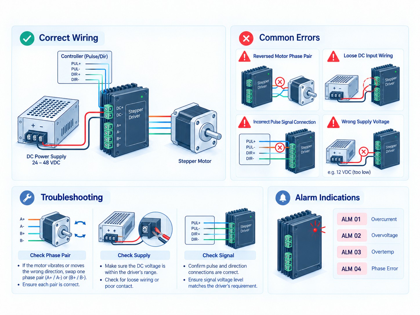
Wiring Errors: The Fastest Troubleshooting Checklist
Many “bad driver” cases are actually wiring errors. Before replacing hardware, isolate the system methodically.
| Symptom | Likely electrical cause | What to check first |
|---|---|---|
| Motor locks but does not rotate | No pulse input, wrong PUL wiring, enable state incorrect | Verify pulse with oscilloscope/logic probe; check PUL+/PUL- and ENA logic |
| Motor vibrates in place | Incorrect phase pairing | Identify A+/A- and B+/B- winding pairs; do not mix one wire from each phase |
| Motor rotates roughly and has very low torque | One phase open or intermittent | Connector, crimp, terminal screw, broken cable, phase continuity |
| Motor runs opposite direction | DIR polarity or one phase reversed | Change controller direction logic or swap A+ and A- as a pair |
| Driver alarms immediately at power-up | Short circuit, phase-to-ground fault, overvoltage or wrong power connection | Disconnect motor and inspect wiring; measure bus voltage before reconnecting |
| Driver alarms only during hard deceleration | Regenerative bus rise | Measure DC bus during decel; lengthen decel or add suitable energy handling |
| Motor gets hot at standstill | Current set too high or idle reduction disabled | Verify current switch and standstill-current mode |
| Motor loses torque at high speed | Bus voltage too low, winding inductance too high, acceleration too aggressive | Compare torque-speed curve; test higher allowed bus voltage or lower-inductance winding |
| Random position errors | EMI coupling into pulse/direction wires | Use twisted/shielded signal pairs, differential signaling, separation from motor cables |
| Controller works at low speed but fails at high speed | Pulse-frequency ceiling | Calculate required kHz from pulses/rev and rpm |
| Driver works with one motor but not another | Current/inductance mismatch or wrong auto-tune | Recheck motor data and run driver auto-identification if supported |
Never connect or disconnect motor leads while energized
This deserves special emphasis. An energized stepper winding stores magnetic energy. Disconnecting the motor cable while current is flowing can create a large voltage transient and damage the driver.
Leadshine's installation manual explicitly warns not to pull or plug the motor connector while the drive is powered. Power down, wait for the DC bus to discharge and verify voltage before changing motor wiring.
Keep motor and pulse cables separated
Motor phase cables carry chopped current with fast edges. PUL/DIR lines are low-energy logic signals. Routing them tightly together over long distances invites interference.
Leadshine recommends twisted-pair shielded cable and physical separation between motor wiring and pulse/direction wiring. In a noisy CNC cabinet with a spindle VFD, contactors and switching power supplies, this is even more important.
A practical wiring layout is:
-
motor cable on one cable route;
-
encoder cable, if used, shielded and separated;
-
pulse/direction or fieldbus cable on a control-signal route;
-
VFD motor output cable kept away from all motion feedback and logic wiring;
-
protective earth bonded to the cabinet using short, low-impedance connections.
Driver Alarm Codes: How to Read the Red LED
Alarm behavior is manufacturer-specific, but many digital stepper drives use a repeating red-LED blink code. Leadshine's DM-series installation manual gives a useful example:
| Red LED blinks per cycle | Example protection meaning | Typical causes to investigate |
|---|---|---|
| 1 | Over-current | Motor phase short, phase-to-ground fault, damaged cable, internal output fault |
| 2 | Over-voltage | Bus voltage too high, excessive regenerative energy, incorrect supply |
| 3 | Low-voltage | Supply collapse, undervoltage, connector drop, supply overload |
| 4 | Phase error | Motor cable open, wrong wiring, phase connection problem |
| 5 | Motor stall protection on models that support it | Mechanical jam, torque deficit, acceleration too high, load exceeded |
Do not assume these blink counts apply to every FRANK HU MOTOR or third-party driver. Use them as a diagnostic pattern and then check the exact model manual.
A good alarm procedure is:
-
Record the blink count before cycling power.
-
Record the motion state when the alarm occurred: idle, acceleration, constant speed or deceleration.
-
Measure the DC bus with a suitable meter or oscilloscope.
-
Inspect the motor cable for phase-to-phase and phase-to-ground faults.
-
Check the motor mechanically for binding.
-
Reduce acceleration and maximum speed temporarily.
-
Verify current and microstep switches.
-
Confirm cooling and cabinet temperature.
-
Reset only after the root cause has been removed.
Repeatedly resetting a driver without diagnosis can turn a simple wiring problem into a damaged power stage.
Motor-to-Driver Compatibility Matrix
The following matrix gives a useful starting point for common machine classes. The current and voltage ranges are planning ranges, not universal specifications for every motor in that frame size.
| Motor / application class | Typical phase-current range | Typical driver bus class | Practical microstep start | Typical machine examples |
|---|---|---|---|---|
| NEMA 8-14 miniature | 0.2-1.5 A | 12-24 VDC | 1/8 to 1/32 | optics, valves, compact instruments |
| NEMA 17 | 0.8-2.5 A | 24-36 VDC | 1/8 to 1/32 | 3D printers, lab stages, small automation |
| NEMA 23 moderate | 2.0-3.0 A | 24-48 VDC | 1/8 to 1/16 | desktop CNC, dispensers, pick-and-place |
| NEMA 23 high-current | 3.0-4.2+ A | 36-60 VDC class | 1/8 to 1/16 | heavier CNC axes, large printers, automation |
| NEMA 24 / small NEMA 34 | 4-6 A | 48-72 VDC class | 1/8 to 1/16 | routers, laser/plasma tables, ball screws |
| High-torque NEMA 34 | 5-7+ A | 60-110 VDC class or appropriate AC-input drive | 1/8 to 1/16 | heavy gantries, rotary tables, industrial positioning |
| NEMA 42 / 51 specialty | 6-12+ A depending on motor | High-voltage DC or mains-class AC driver | Application specific | heavy industrial machines and large indexing axes |
Why are these ranges broad? Because frame size does not define winding design. A high-current, low-inductance winding in the same frame can be optimized for speed, while a lower-current, high-inductance winding may behave differently even if holding torque is similar.
That is why the first technical documents you should request from a supplier are:
-
rated phase current;
-
phase resistance;
-
phase inductance;
-
holding torque;
-
rotor inertia;
-
step angle;
-
torque-speed curves at one or more driver voltages;
-
recommended driver model;
-
recommended wiring for 6- or 8-lead motors.
Worked Example 1: NEMA 23, 2.8 A Motor for a CNC Router
Assume a 1.8° NEMA 23 motor with:
-
rated phase current: 2.8 A;
-
moderate winding inductance;
-
holding torque around 1.2-1.9 N·m depending on motor length;
-
target speed: 800 rpm;
-
ball screw or belt axis requiring smooth interpolation.
Step 1: Current capability
Choose a driver whose output-current range comfortably includes the motor's 2.8 A rating under the correct current convention. Avoid a driver that can only reach 2.2 A if the application needs full motor torque.
Step 2: Voltage
For 800 rpm, a 24 V bus may work in a light-load application but can leave significant high-speed torque unused. A 36 V or 48 V driver/supply combination is often a stronger starting point if the motor inductance and driver rating permit it.
The correct answer comes from the torque-speed curve. If the curve shows adequate torque at 800 rpm on 36 V, there is no need to use 72 V simply because a higher-voltage driver exists.
Step 3: Microstepping
Start with 1/8 or 1/16.
At 800 rpm:
-
1/8: 1,600 x 800 / 60 = 21.3 kHz
-
1/16: 3,200 x 800 / 60 = 42.7 kHz
-
1/32: 6,400 x 800 / 60 = 85.3 kHz
All are manageable for many CNC controllers, but 1/16 usually offers enough command resolution without unnecessary pulse load.
Step 4: Thermal test
Run the heaviest expected duty cycle. Check motor and driver temperatures after thermal stabilization. If the motor is much hotter than necessary, reduce current slightly or use idle-current reduction while verifying that required holding torque remains available.
Worked Example 2: NEMA 34, 6 A Motor for a Heavy Gantry
Assume a 1.8° NEMA 34 motor with:
-
6 A rated phase current;
-
high holding torque;
-
larger winding inductance than the NEMA 23 example;
-
target rapid speed: 1,000 rpm;
-
heavy router or plasma gantry.
FRANK HU MOTOR's catalog includes NEMA 34 examples in the 6 A class and long-stack motors with holding torque reaching the double-digit N·m range, demonstrating how demanding this frame family can become.
Step 1: Driver current
A 4.2 A or 5.6 A RMS-limited driver may be insufficient depending on the motor rating and current convention. A higher-current driver such as the OK2D872 class can be more appropriate, but the exact current switch must still be matched to the motor wiring.
Step 2: Driver voltage
This is where high-voltage capability matters. A 24 V supply is generally a poor choice for a large high-inductance NEMA 34 if the machine needs strong torque at 1,000 rpm. A 60-72 V class bus is often much more realistic, and some applications may justify still higher voltage if the torque-speed data support it and the driver provides adequate margin.
The OK2D872's wide input range makes it useful for this type of optimization because the machine builder can test or design around several bus levels without changing to a completely different driver class.
Step 3: Pulse frequency
At 1,000 rpm:
-
1/8 microstep = 26.7 kHz
-
1/16 = 53.3 kHz
-
1/32 = 106.7 kHz
-
1/64 = 213.3 kHz
If the driver limit is 200 kHz, 1/64 already exceeds the input limit. Therefore, 1/8 or 1/16 is normally a more rational external command resolution for a high-speed gantry unless the controller/driver combination uses internal interpolation.
Step 4: Deceleration and regeneration
A heavy gantry stores much more kinetic energy than a small XY table. If an overvoltage alarm appears only when the axis decelerates from rapid speed, do not lower motor current first. Measure the bus and investigate regenerative energy handling.
Worked Example 3: 24 V Laboratory Axis Where Higher Voltage Is Not Necessary
Consider a NEMA 17 linear stage that moves only 50 mm, reaches 150 rpm, carries a light optical load and requires quiet operation rather than high rapid speed.
A 24 V driver can be an excellent choice because:
-
the motor has enough time for current to rise at the low target speed;
-
the machine already uses a 24 V PLC supply;
-
lower bus voltage reduces unnecessary switching stress;
-
1/16 or 1/32 microstepping can improve low-speed smoothness;
-
standstill-current reduction can minimize thermal drift near optical components.
Using a 72 V driver would add cost, safety complexity and switching stress without necessarily improving the machine result.
This example is important because good engineering is not about maximizing every specification. It is about matching the specification to the application.
Application Recommendations
3D printers
For standard desktop 3D printers, 24 V is common and usually sufficient because NEMA 17 motors operate at moderate speed with relatively light loads. The priorities are smoothness, low noise, thermal control and compact electronics. High microstepping or internal interpolation is valuable for acoustic quality, but actual print accuracy is still dominated by belts, lead screws, extrusion mechanics and frame stiffness.
For large-format printers with heavy beds or gantries, higher bus voltage and larger motors may be justified.
CNC routers and engraving machines
CNC routers often benefit from 36-72 V class systems depending on motor size and rapid speed. The driver must preserve torque at the rpm created by the screw lead or rack-pinion ratio.
A 10 mm lead ball screw traveling at 10 m/min requires:
10,000 mm/min / 10 mm/rev = 1,000 rpm
At that speed, driver voltage and winding inductance are critical. Selecting only by holding torque is a common reason for disappointing rapid speed.
Laser and plasma cutting machines
These systems often require rapid traversal with relatively low process force. That means high-speed torque can matter more than enormous holding torque. A lower-inductance motor with a higher-voltage driver can outperform a larger but slow-winding motor.
Plasma machines also have severe electrical noise, so differential pulse signaling, cable separation, shielding and grounding deserve special attention.
Pick-and-place and packaging
These machines often operate with repeated acceleration and deceleration. Peak torque, inertia matching, bus regeneration and driver alarm diagnostics are important. High microstep settings can improve low-speed smoothness, but controller pulse bandwidth must be checked at production speed.
If a missed step would create scrap without immediate detection, a closed-loop stepper or servo may be a better business decision than an open-loop drive.
Precision instruments and laboratory automation
Low noise, thermal drift and repeatability may matter more than top speed. Use sufficient but not excessive current and voltage. Standstill-current reduction is especially useful when motor heat could move a sensitive optical or metrology structure.
A Procurement Checklist for Stepper Driver Selection
Before ordering, send your supplier the following information:
-
Motor part number.
-
Motor phase count.
-
Step angle.
-
Rated current per phase and current convention if known.
-
Phase resistance.
-
Phase inductance.
-
Number of motor leads and intended series/parallel/half-coil wiring.
-
Required motor speed in rpm.
-
Required torque at the highest important speed, not only holding torque.
-
Maximum acceleration/deceleration.
-
Load inertia or enough mechanical data to calculate it.
-
Available power source: 24, 36, 48, 72, 110 VDC, AC input, etc.
-
Controller interface: PUL/DIR, CW/CCW, 5 V, 24 V, differential, PLC, fieldbus.
-
Maximum controller pulse frequency.
-
Desired microstep resolution.
-
Number of axes sharing one power supply.
-
Ambient and cabinet temperature.
-
Whether forced cooling is available.
-
Whether the application needs alarm output or closed-loop feedback.
-
Safety/regulatory requirements for the destination machine.
With those data, a supplier can recommend a driver and power supply as a system instead of guessing from the NEMA size.
A Five-Minute Decision Workflow
If you need a fast way to choose a stepper motor driver, use this sequence:
1. Match phase topology
Two-phase motor -> two-phase driver. Three-phase motor -> three-phase driver. Closed-loop motor -> compatible feedback driver if closed-loop operation is required.
2. Match phase current correctly
Confirm peak versus RMS and the motor wiring configuration. Select a driver with enough current range and thermal margin.
3. Choose bus voltage from speed and inductance
Low-speed compact axis: 24 V may be enough. Medium-speed NEMA 23: 36-48 V is common. Large NEMA 34 at high speed: 60-72 V or higher may be justified. Never exceed the driver's input range.
4. Check pulse frequency
Calculate:
Pulse frequency = pulses/rev x rpm / 60
Make sure both the controller output and driver input can handle the result.
5. Start with moderate microstepping
1/8 or 1/16 is a strong default for many machines. Increase only when it improves motion quality without creating pulse-bandwidth problems.
6. Check the power supply as a dynamic component
Verify overload behavior, shared-axis demand, bus capacitance, regenerative energy and voltage margin.
7. Wire for industrial noise immunity
Separate motor and signal cables, use twisted/shielded pairs where appropriate and apply correct grounding.
8. Commission thermally
Run the real motion cycle long enough for temperatures to stabilize. A driver that works for five minutes may overheat after two hours in a closed cabinet.
Frequently Asked Questions
Can I use a 48 V power supply with a 3 V stepper motor?
Yes, this is normal with a modern chopper current-regulating driver if the driver is rated for 48 V, the motor current is set correctly and the combination is within the motor/driver application limits. The 3 V figure is usually derived from winding resistance and rated current; it is not the required DC bus voltage.
Should I choose driver voltage from motor rated voltage?
No. Choose driver bus voltage from the driver's allowable range, motor inductance, required speed and torque-speed curve. Motor rated winding voltage and driver supply voltage describe different things.
Does a higher-voltage stepper driver increase torque?
It mainly helps preserve torque as speed increases because it forces winding current to rise faster against inductance and back EMF. At low speed, torque is primarily controlled by phase current once the target current is reached.
What happens if the stepper driver current is too high?
Motor and driver heating increase, often sharply because copper loss rises approximately with I²R. Excessive current can shorten life, trigger thermal protection or damage the motor/driver.
What happens if driver current is too low?
The motor produces less torque. It may appear fine when unloaded but stall or lose steps during acceleration or under process load.
Is 1/16 microstepping more accurate than 1/8?
It provides twice the command resolution and can improve smoothness, but it does not guarantee twice the mechanical positioning accuracy. Load, motor construction, driver current accuracy and mechanics still determine real position error.
How many microsteps should I use for CNC?
For many CNC routers and linear axes, 1/8 or 1/16 is a practical starting point. Check machine resolution and pulse-frequency requirements before choosing 1/32 or higher.
Why does my stepper lose torque at high speed?
Winding inductance slows current rise and back EMF increases with speed. If the driver cannot establish the commanded current quickly enough, torque falls. Higher allowed bus voltage, lower-inductance windings and a suitable driver can improve performance.
Can one power supply run multiple stepper drivers?
Yes, if it has enough voltage, continuous/peak power and suitable dynamic behavior. Connect each driver separately back to the supply distribution point instead of daisy-chaining power through the drivers.
Why is my driver's power-supply current lower than motor phase current?
Because the driver is a switching current regulator and energy circulates in the motor/driver during PWM operation. DC input current is not the same as winding phase current.
Should I use an AC-input or DC-input stepper driver?
Use DC input when the machine already has a suitable DC bus or centralized power supply. Use AC input when a high-power/high-voltage driver architecture is more practical and the machine can support the required electrical safety. Dual-input drivers provide additional flexibility.
What is the best driver for a NEMA 34 stepper motor?
There is no single NEMA 34 driver. NEMA 34 motors vary widely in current, inductance and torque. For a 6 A high-torque motor, a high-current and often higher-voltage driver is normally required; for a smaller NEMA 34 with lower current and modest speed, a lower-power drive may be sufficient. Start from the exact motor data.
Is OK2D872 suitable for NEMA 23 as well as NEMA 34?
The FRANK HU MOTOR product listing describes the OK2D872 as suitable for a wide range of 2-phase NEMA 23, NEMA 24 and NEMA 34 motors, subject to matching the motor current, supply voltage, wiring and application requirements. Its wide 24-110 VDC / 18-80 VAC input class makes it especially useful when more high-speed torque is required than a 24-50 V drive can provide.
Do I need a closed-loop stepper driver?
Not always. Open-loop steppers are economical and reliable when the load and acceleration are predictable and there is adequate torque margin. Choose closed loop when missed motion must be detected, load variation is significant, or diagnostic visibility is worth the additional cost.
Final Recommendation
The best stepper motor driver is not the one with the largest voltage number, highest current number or maximum microstep setting. It is the one that gives the motor enough current at low speed, enough bus voltage to preserve torque at the required high speed, enough pulse bandwidth for the selected microstepping, enough thermal margin for the real duty cycle, and enough protection for the machine environment.
For most projects, make the selection in this order:
-
Motor phase topology and wiring
-
Rated phase current and current convention
-
Required speed and motor inductance
-
Driver bus-voltage range
-
Power-supply voltage and dynamic capacity
-
Microstep setting and pulse-frequency requirement
-
Control-signal compatibility
-
Cooling, protection and alarm functions
-
Real torque-speed and thermal validation
If the machine already has a selected stepper motor, FRANK HU MOTOR can match it with a suitable driver, power supply and control configuration. The covers compact low-voltage drives through high-current, high-voltage options, while the provides common 24 V, 36 V and 48 V sources for motion-control cabinets.
For larger CNC and automation axes, the is a practical example of why driver selection must go beyond the motor's nameplate voltage. Its value is not simply “high voltage”; it is the ability to combine a wide bus range, adjustable current, industrial control signals and high pulse frequency so the machine builder can tune the electrical system around the actual torque-speed requirement.