stepper motor for a 3D printer looks simple until you try to optimize the whole machine. Most desktop FDM printers use NEMA 17 motors, but “NEMA 17” only tells you the 42 mm mounting frame. It does not tell you whether the motor is light enough for a direct-drive toolhead, powerful enough for a heavy bed, low-inductance enough for a high-speed CoreXY machine, or thermally suitable for a compact extruder.
A good 3D-printer motor selection therefore starts with the axis, not with a single torque number.
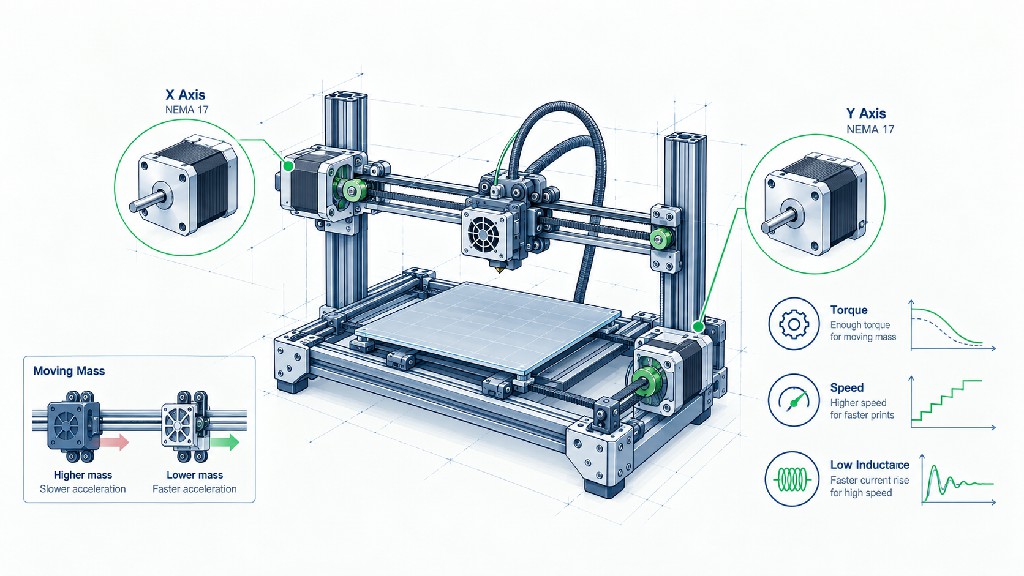
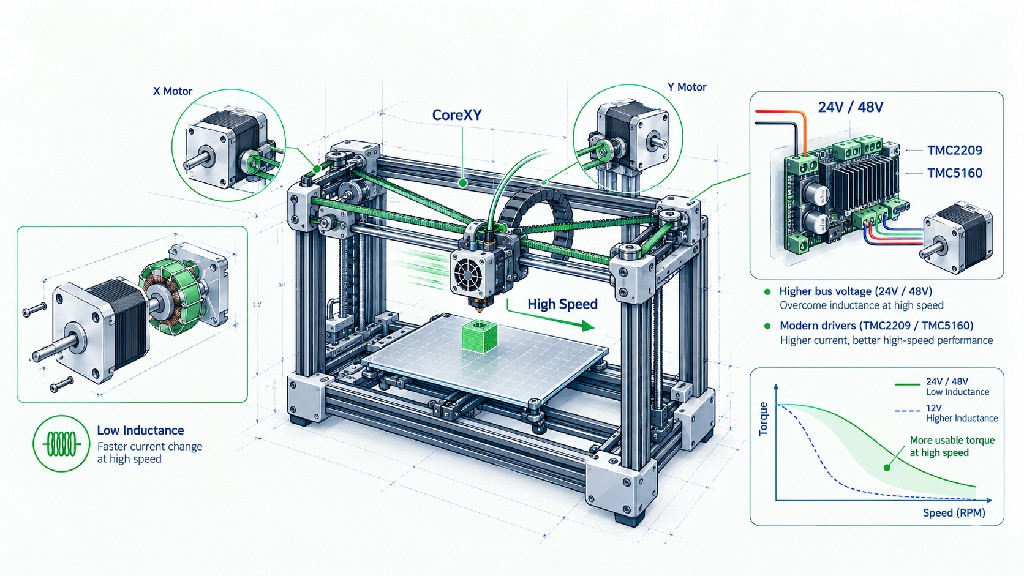
An X/Y motor needs dynamic torque at hundreds or sometimes more than one thousand revolutions per minute. A Z motor usually runs much more slowly, so holding torque and screw mechanics matter more than extreme high-speed performance. A direct-drive extruder benefits from a short, light motor because every gram moves with the printhead, while a Bowden extruder can tolerate a longer, higher-torque motor mounted on the frame. CoreXY and high-speed printers add another requirement: low electrical inductance and a suitable high-voltage driver become increasingly important because winding current must rise quickly as step frequency increases.
This guide explains how to select a motor as a complete motor + driver + voltage + mechanics system. It also shows why the “best NEMA 17 stepper motor for a 3D printer” is different for X/Y motion, Z lifting, direct drive extrusion, Bowden extrusion, CoreXY kinematics, and high-speed printing.
For buyers who want to compare actual 42 mm motors, FRANK HU MOTOR maintains a broad covering 0.9° and 1.8° step angles, short and long motor bodies, and multiple current/torque combinations. For a broader frame-size explanation, see the .
Quick Answer: Which Stepper Motor Should You Use?
The table below is a practical engineering starting point, not a universal specification. Final selection should be validated with the exact motor torque-speed curve, the driver current limit, the supply voltage, the moving mass, pulley or screw geometry, acceleration target, enclosure temperature, and print duty cycle.
| 3D Printer Position | Practical Motor Direction | Why |
|---|---|---|
| X/Y on conventional Cartesian printer | NEMA 17, typically medium-length, moderate-to-high dynamic torque | Must accelerate belt-driven mass while retaining torque at several hundred rpm |
| Z axis | NEMA 17, usually 1.8°, moderate holding torque; integrated lead-screw motor can simplify mechanics | Z speed is low; screw lead, bed mass, gravity and anti-backdrive behavior dominate |
| Direct-drive extruder | Short or pancake NEMA 17, often geared extruder | Lower toolhead mass improves acceleration, but thermal margin must be checked carefully |
| Bowden extruder | Standard or longer NEMA 17 with generous torque | Motor is frame-mounted, so extra mass is less harmful |
| CoreXY | Low-inductance NEMA 17 with good high-speed torque and low rotor inertia | Motors may spin rapidly and see aggressive acceleration while remaining frame-mounted |
| High-speed 24 V printer | Low-inductance motor + well-cooled TMC2209-class driver, if current demand fits | 24 V is practical and common, but the driver and winding must retain enough high-speed torque |
| High-speed 48 V printer | Low-inductance motor + 48 V-capable driver such as a correctly implemented TMC5160-class solution | Higher bus voltage can improve current rise and high-speed torque, but requires appropriate electronics and transient margin |
A useful rule is: choose the shortest and lightest motor that still meets the required dynamic torque at the actual operating speed. Oversizing only for holding torque can make a fast axis worse because a longer motor also has more rotor inertia and more mass.
NEMA 17 Is a Frame Size, Not a Performance Rating
NEMA 17 is strongly associated with 3D printers because its approximately 42 × 42 mm face provides a useful balance of size, cost and torque. But two NEMA 17 motors can behave very differently.
Within the current FRANK HU MOTOR , examples include very short 1.8° motors around 20–22 mm body length, mainstream 40 mm motors, longer 48 mm motors, and 0.9° versions with 400 full steps per revolution. Holding-torque examples range from roughly 0.14 N·m for a compact 20 mm motor to around 0.45–0.50 N·m for common 40–48 mm variants, depending on winding and design.
That spread is exactly why buyers should not specify only “NEMA 17.” A complete motor specification should include at least:
-
step angle;
-
phase current;
-
phase resistance;
-
phase inductance;
-
holding torque;
-
body length;
-
shaft diameter and shaft length;
-
rotor inertia, when available;
-
insulation and temperature limits;
-
connector/wiring requirements;
-
expected drive voltage and driver type.
FRANK HU MOTOR’s guide explains the same principle for general motion systems: holding torque is only a starting data point. A correct design must prove torque at the required speed and must include inertia, acceleration and thermal checks.
The Six Motor Jobs Inside a 3D Printer
A 3D printer may use several motors that look physically identical but perform completely different mechanical jobs. Treating them as interchangeable is one of the most common mistakes in DIY and small-batch printer design.
X/Y Axis Motor
The X and Y motors convert rotational motion into linear motion through belts and pulleys in most FDM printers. Their main challenge is not static load. It is acceleration.
When a printer changes direction at a corner, the motor must accelerate the carriage, bed, gantry components, belts, idlers and its own rotor. The required motor torque includes both external load torque and acceleration torque:
T_required = T_load + J_total × α
where J_total is the total rotational inertia reflected to the motor shaft and α is angular acceleration.
For this reason, a 0.60 N·m motor is not automatically better than a 0.45 N·m motor. If the higher-torque motor has a much heavier rotor, the extra inertia can reduce how quickly the system changes speed. High-speed printers need a balance between torque and inertia, not maximum holding torque at any cost.
For mainstream Cartesian printers, a medium-length NEMA 17 around the 34–48 mm class is common. The exact choice depends on moving mass and acceleration target. A moving-bed Y axis usually has a much heavier load than an X carriage, so it may need more torque or a lower acceleration limit.
Z Axis Motor
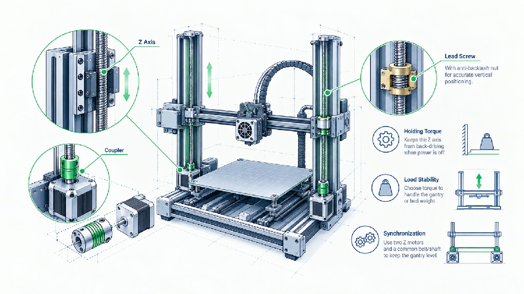
The Z axis is different. It often uses a lead screw and rotates slowly. That means high-speed torque is less important than:
-
lifting force;
-
holding torque;
-
screw lead;
-
screw efficiency;
-
vertical load and gravity;
-
synchronization between multiple Z motors;
-
risk of the axis dropping when power is removed.
A 1.8° motor is normally sufficient for Z motion because the screw already provides substantial mechanical resolution. For example, an 8 mm lead screw moves 8 mm per revolution. With a 1.8° motor (200 full steps/rev), one full step corresponds to:
8 / 200 = 0.04 mm per full step
At 16 microsteps, the command increment is 0.0025 mm. A 0.9° motor halves those theoretical increments, but actual Z accuracy still depends on screw lead error, straightness, bearing arrangement, frame stiffness, microstep linearity and bed mechanics.
FRANK HU MOTOR offers purpose-built with the lead screw integrated directly into the motor. One example uses a NEMA 17 motor, 4 mm lead, 1.8° step angle, 2.0 A phase current and 0.4 N·m holding torque. Integrated screw motors can reduce coupler count and alignment errors in compact Z-axis designs.
Direct-Drive Extruder Motor
The direct-drive extruder motor travels with the printhead. That changes the optimization target dramatically.
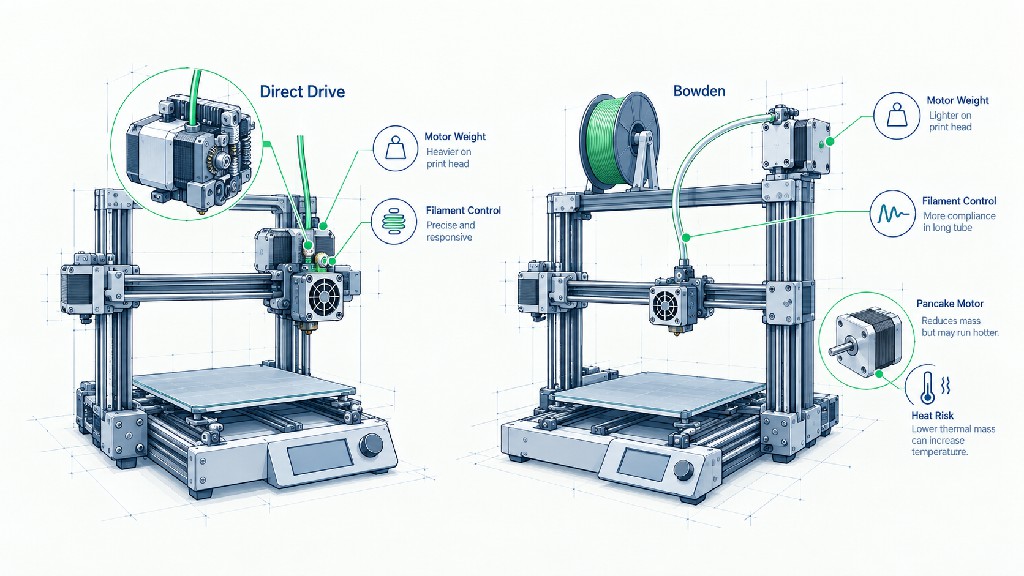
A 48 mm-long NEMA 17 may provide strong holding torque, but its mass is carried by the X/Y motion system. That extra moving mass increases required acceleration force and can worsen ringing, belt load and frame vibration. This is why geared direct-drive extruders often use short NEMA 17 motors or “pancake” motors.
The challenge is that a pancake motor has less magnetic material, less copper and less thermal mass than a long motor. It may run hot if the current is set aggressively, especially near a heated hot end, inside an enclosure or with limited airflow.
A direct-drive extruder should therefore be chosen by gear ratio + required filament force + motor current + thermal margin + moving mass, not by motor thickness alone.
Bowden Extruder Motor
A Bowden extruder motor is mounted on the frame rather than on the moving toolhead. The motor can therefore be longer and heavier without directly increasing carriage inertia.
That makes a standard 40 mm or 48 mm NEMA 17 a practical choice when high filament force is needed. Bowden systems may require higher retraction distances and can experience significant filament friction through the tube, so torque margin is useful.
A mainstream 40 mm FRANK HU MOTOR example is the . Its class is representative of the conventional “full-size” NEMA 17 used in many 3D printers.
CoreXY Printer Motor
CoreXY is one of the most demanding common 3D-printer kinematics for X/Y motors. The motors are mounted on the frame, which is good because motor mass does not move with the toolhead. However, the motors can rotate very quickly, especially during diagonal motion.
In ideal CoreXY kinematics, motor coordinates can be expressed as combinations of Cartesian X and Y motion. One simplified representation is:
A = X + Y
B = X - Y
This means one motor can see a much higher rotational speed during certain diagonal moves while the other slows or stops. Therefore, a motor that feels powerful during a straight X move may lose torque on a high-speed diagonal move.
For CoreXY, low inductance, appropriate current, low-to-moderate rotor inertia and strong high-speed torque are often more important than the largest holding-torque number.
High-Speed Printer Motor
High-speed printing pushes every weakness of the motor-drive system into view.
At high rotational speed, winding current has less time to rise before the driver commutates to the next electrical state. The motor’s inductance opposes rapid current change. Texas Instruments summarizes the relationship with the familiar electrical law V = L × dI/dt, and notes that a wider operating speed range can be obtained through lower inductance, lower current level in some conditions, and higher supply voltage. See TI’s for the electrical explanation.
Oriental Motor gives the same engineering message in its : winding inductance limits high-speed current rise, while higher drive voltage improves high-speed performance by forcing current into the winding faster.
So for a high-speed 3D printer, the motor should be selected from its torque-speed behavior under the proposed voltage and current—not from holding torque alone.
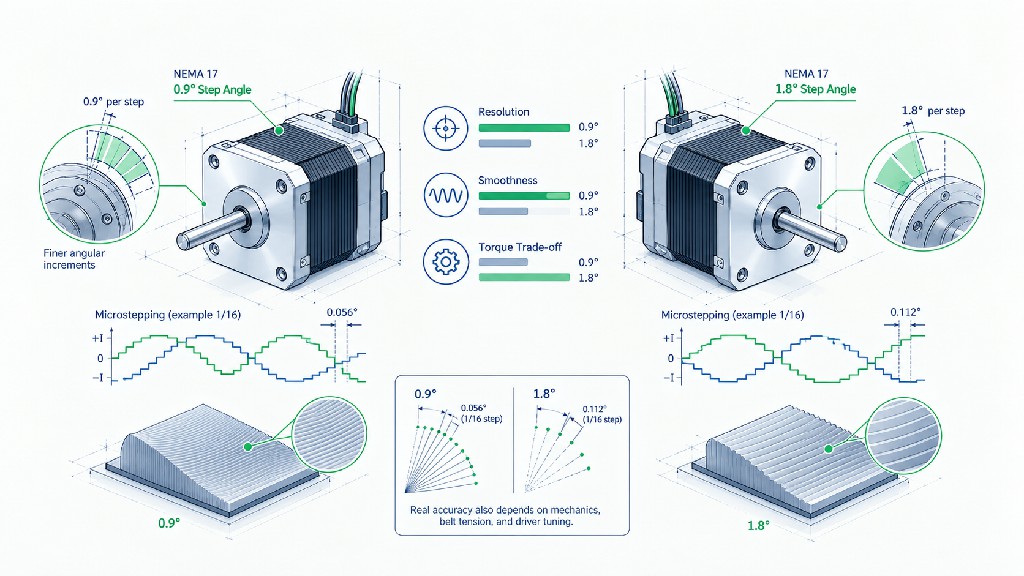
0.9° vs 1.8° Stepper Motor: Which Is Better for a 3D Printer?
The 0.9 degree vs 1.8 degree stepper question is one of the most searched topics in 3D-printer motor selection.
A 1.8° hybrid stepper has 200 full steps per revolution:
360 / 1.8 = 200 full steps per revolution
A 0.9° motor has 400 full steps per revolution:
360 / 0.9 = 400 full steps per revolution
That is a real doubling of full-step angular resolution. But it does not mean the printer becomes twice as dimensionally accurate.
Analog Devices explains in its technical article that microstepping increases commanded resolution and smoothness, but positional accuracy remains dependent on motor construction tolerances, load and the driver’s current-control accuracy. That distinction is important for 3D printers, where belts, pulleys, frame vibration, extrusion pressure and resonance can dominate print quality.
Resolution Example with a GT2 Belt
Assume a 20-tooth GT2 pulley with 2 mm belt pitch. The pulley moves:
20 × 2 = 40 mm per revolution
For a 1.8° motor:
-
200 full steps/rev;
-
40 / 200 = 0.200 mm per full step;
-
at 16 microsteps: 0.0125 mm command increment.
For a 0.9° motor:
-
400 full steps/rev;
-
40 / 400 = 0.100 mm per full step;
-
at 16 microsteps: 0.00625 mm command increment.
The command resolution doubles, but mechanical accuracy does not automatically double.
Pulse-Rate Penalty of 0.9° Motors
The extra full steps also mean the controller must generate twice as many step pulses for the same shaft speed if the same microstep setting is used.
| Motor | Full Steps/Rev | 16× Microsteps/Rev | Pulses/s at 750 rpm | Pulses/s at 1500 rpm |
|---|---|---|---|---|
| 1.8° | 200 | 3,200 | 40,000 | 80,000 |
| 0.9° | 400 | 6,400 | 80,000 | 160,000 |
Modern 32-bit printer controllers usually handle these rates, but pulse generation, firmware configuration and driver mode still matter. On extremely fast machines, a 0.9° motor can consume more motion-control bandwidth without delivering a proportional real-world print-quality gain.
When 0.9° Is Attractive
A 0.9° motor can be attractive when:
-
low-speed smoothness and reduced full-step angular jump are priorities;
-
the machine has enough controller pulse-rate margin;
-
you want more full-step positions per revolution without relying solely on high microstep ratios;
-
the selected 0.9° motor also has suitable inductance and dynamic torque.
FRANK HU MOTOR lists 0.9° NEMA 17 options including compact and full-length versions. For example, the catalog includes 26 mm 0.9° models and 48 mm models around the 0.44 N·m class. A detailed example is the , which specifies 4.1 mH inductance.
When 1.8° Is the Better Choice
A 1.8° motor remains an excellent default when:
-
controller step-rate margin is more valuable than doubled full-step resolution;
-
the machine already uses 16× or 32× microstepping;
-
the chosen 1.8° winding has better high-speed torque or lower inductance;
-
the application is Z motion, where screw mechanics already provide high resolution;
-
the printer is cost-sensitive and a conventional motor is easier to source.
There is no universal winner. Compare the exact motor’s current, inductance, torque-speed curve, rotor inertia and thermal behavior.
3D Printer Stepper Motor Torque: Why Holding Torque Is Not Enough
The phrase 3D printer stepper motor torque often leads buyers to compare only holding torque. That is useful for Z axes and static loads, but it can be misleading for X/Y motion.
Holding torque is measured at standstill under specified current conditions. A belt-driven axis may operate at 300, 600, 900, 1200 rpm or more. Available torque usually falls with speed because winding inductance and back EMF prevent phase current from reaching its commanded value quickly enough.
FRANK HU MOTOR’s explains why the torque-speed curve should be the decisive document for dynamic sizing. The curve must ideally match the same motor winding, current, supply voltage and driver method you intend to use.
Belt-Speed Example
With a 20-tooth GT2 pulley, travel per revolution is 40 mm.
Motor speed is:
Motor rpm = (linear speed / 40 mm per revolution) × 60
| Linear Speed | Motor Speed |
|---|---|
| 100 mm/s | 150 rpm |
| 200 mm/s | 300 rpm |
| 300 mm/s | 450 rpm |
| 500 mm/s | 750 rpm |
| 700 mm/s | 1050 rpm |
| 1000 mm/s | 1500 rpm |
This table immediately explains why a motor that feels exceptionally strong when you twist the shaft by hand can still skip steps at 700–1000 mm/s. The machine is operating far away from the static holding-torque condition.
Required Torque Also Depends on Acceleration
A 500 mm/s travel speed with gentle acceleration can be easier on the motor than a 300 mm/s profile with extremely high acceleration and frequent direction reversals.
Linear acceleration force follows:
F = m × a
For a belt pulley of pitch radius r, the ideal torque contribution is approximately:
T = F × r
before adding friction, belt preload effects, rotor inertia and safety margin.
This is why “high-speed printer” should not mean only high top speed. Acceleration, toolhead mass and motion profile matter at least as much.
High Torque vs High Rotor Inertia
Longer NEMA 17 motors typically contain more active magnetic material and can produce more holding torque, but they also usually contain a larger rotor with higher rotational inertia.
Acceleration torque follows:
T_a = J × α
If rotor inertia J increases, more torque is consumed just accelerating the motor itself. This is especially important in high-acceleration CoreXY designs.
The practical result is a tradeoff:
-
long motor: more torque capacity, more mass, typically more rotor inertia;
-
short motor: lower mass and inertia, less torque reserve;
-
best high-speed choice: the smallest rotor that still provides adequate torque margin at the target rpm.
This is also why replacing a 40 mm motor with a 60 mm motor does not automatically allow higher acceleration. The extra torque may be partially cancelled by extra inertia, and the winding may have higher inductance.
For direct-drive extruders, body mass matters twice: the motor rotor must be accelerated internally, and the entire motor body must be accelerated as part of the toolhead.
Why Low Inductance Matters for High-Speed 3D Printing
A low inductance stepper motor can be a major advantage at high speed.
The winding behaves electrically as an inductive load. A simplified current-rise relationship is:
V = L × (dI/dt) + I × R + E_back
At low speed, there is enough time for current to rise near the requested value. At high speed, each electrical state becomes shorter. If inductance is high, current may not build quickly enough before the next commutation event.
TI’s stepper-driver engineering report explicitly states that the current rise time depends on supply voltage, coil inductance and coil current, and identifies low inductance plus higher supply voltage as ways to extend useful operating speed. Oriental Motor similarly describes the winding time constant and the loss of torque when current cannot rise rapidly enough.
What “Low Inductance” Should Mean in Purchasing
Do not use one universal millihenry threshold for every NEMA 17 motor. Inductance must be interpreted with:
-
phase current;
-
phase resistance;
-
number of turns;
-
motor length;
-
torque target;
-
driver voltage;
-
rotor design.
The correct purchasing strategy is comparative: when two motors both meet your low-speed torque requirement, the lower-inductance winding will often retain current and torque better as speed rises, assuming the driver can supply the required current.
This makes inductance especially important for:
-
CoreXY A/B motors;
-
very fast Cartesian axes;
-
48 V performance builds;
-
machines targeting high acceleration and high travel speed simultaneously.
It matters less for a slow Z screw that might operate at only 50–200 rpm.
24 V vs 48 V Stepper Motor Systems
Most modern desktop 3D printers use 24 V electronics. High-performance printers increasingly explore 48 V motion systems for X/Y.
The benefit of higher bus voltage is electrical, not magical. A current-regulated chopper driver uses the higher voltage to make winding current rise faster, then regulates current to the configured level. Pololu’s explains that a supply voltage may be higher than the motor’s simple winding voltage when active current limiting is used. The objective is to control current correctly while improving dynamic current rise.
24 V Advantages
24 V remains the best default for a large percentage of printers because it offers:
-
broad controller-board availability;
-
straightforward heater, fan and accessory integration;
-
compatibility with TMC2209-class drivers;
-
lower electrical stress than 48 V;
-
sufficient performance for many printers in the 150–400 mm/s range, depending on mechanics.
48 V Advantages
A properly engineered 48 V X/Y system can provide:
-
faster winding current rise;
-
improved torque retention at high rpm;
-
greater high-speed margin with suitable low-inductance motors;
-
potential benefit for large CoreXY machines or aggressive acceleration profiles.
However, 48 V requires more than changing the power supply.
You must verify:
-
driver IC and driver module voltage rating;
-
MOSFET and capacitor voltage margin;
-
connector and PCB creepage/clearance design;
-
transient and regenerative voltage spikes;
-
motor winding current and thermal limits;
-
firmware configuration;
-
grounding and protection strategy.
Do not run a TMC2209 motor stage from 48 V. Analog Devices specifies the for a 4.75–29 V DC supply range. By contrast, the supports 8–60 V and uses external MOSFETs for higher-power designs. The complete board, not just the IC, must still be rated for the intended voltage.
24 V vs 48 V Summary
| Factor | 24 V System | 48 V System |
|---|---|---|
| Main use | Mainstream printers | High-speed/performance axes |
| Typical driver family | TMC2209, TMC2240-class solutions depending board | TMC5160-class or other explicitly 48 V-capable solution |
| High-rpm torque | Good with suitable motor | Potentially stronger due to faster current rise |
| Electronics complexity | Lower | Higher |
| Transient-voltage concern | Moderate | More critical |
| Motor heating | Determined mainly by current and winding losses | Still determined mainly by current and winding losses; higher bus voltage does not mean you should exceed rated current |
| Recommended for extruder/Z | Usually sufficient | Often unnecessary |
TMC2209 vs TMC5160: Matching the Driver to the Motor
The motor and driver should be selected together. FRANK HU MOTOR’s explains the general matching process: verify voltage, phase current, step/direction interface, cooling, current-control method and application environment.
TMC2209
Analog Devices positions the TMC2209 specifically for applications including 3D printers. Its official product data lists:
-
4.75–29 V DC motor supply;
-
up to 2 A RMS / 2.8 A peak coil-current capability at the IC level;
-
UART configuration;
-
StealthChop2;
-
SpreadCycle;
-
StallGuard4;
-
up to 256 microsteps through interpolation/control features.
In a real printer motherboard, usable continuous current may be lower than the silicon maximum because the tiny driver module must dissipate heat through PCB copper, heatsinks and airflow.
The TMC2209 is an excellent fit for many 24 V NEMA 17 applications, especially where silence, cost and compact integration matter.
TMC5160
The TMC5160 is a higher-power controller/driver architecture with external MOSFETs. Analog Devices specifies:
-
8–60 V DC motor supply;
-
external transistor stage for currents from roughly 1 A to several tens of amps depending on implementation;
-
SPI and UART-related control options;
-
StealthChop2;
-
SpreadCycle;
-
StallGuard2;
-
encoder interface;
-
up to 256 microsteps.
Analog Devices explicitly lists high-speed 3D printers among TMC5160 applications. It is therefore a logical family for 48 V X/Y motion when the complete board is designed correctly.
Firmware Compatibility
Modern 3D-printer firmware supports many Trinamic drivers. Marlin’s lists TMC2209 and TMC5160 among supported configurable drivers and describes features such as StealthChop, driver monitoring and sensorless homing.
Firmware support alone does not guarantee electrical compatibility. The PCB must expose the appropriate UART/SPI connections, current-sense configuration and voltage-rated power stage.
Microstepping: More Resolution Does Not Mean Proportionally More Accuracy
Microstepping is extremely valuable in 3D printers because it reduces noise, vibration and abrupt full-step motion. But it is frequently misunderstood.
At 16× microstepping, a 1.8° motor is commanded in 3,200 increments per revolution. A 0.9° motor is commanded in 6,400 increments per revolution. Drivers such as the TMC2209 and TMC5160 can interpolate to much finer internal current states.
However, the motor does not produce equal incremental torque at every tiny microstep position. Analog Devices’ microstepping article shows that incremental holding torque becomes smaller as the microstep division becomes finer. The article also stresses that higher microstep resolution does not automatically increase absolute position accuracy.
For printer design, use microstepping mainly for:
-
smoother motion;
-
quieter operation;
-
reduced low-speed vibration;
-
finer command granularity.
Do not use a 1/256 setting simply because the number sounds more precise. Very high command microstep ratios increase pulse rate and may provide little print-quality benefit compared with a sensible 16× or 32× command mode plus driver interpolation.
Choosing an X/Y Motor for a Cartesian 3D Printer
For a conventional belt-driven Cartesian printer, start with these questions:
-
Is the moving mass a light toolhead or a complete print bed?
-
What is the target maximum speed?
-
What is the target acceleration?
-
What pulley size is used?
-
Is the supply 24 V or 48 V?
-
What continuous phase current can the driver actually deliver?
-
What torque is available at the target rpm?
Practical Starting Direction
For many mainstream printers, a 34–48 mm NEMA 17 around the 0.35–0.50 N·m holding-torque class is a reasonable starting family. But choose between candidates using high-speed torque and rotor inertia.
A 40 mm, 1.8° motor around 0.45 N·m is a common general-purpose class. FRANK HU MOTOR’s is one example.
For a bed-slinger Y axis, the bed mass may justify more torque or lower acceleration. For a lightweight X carriage, a slightly shorter motor can reduce frame mass and cost while still meeting the dynamic requirement.
Avoid This Mistake
Do not calculate torque only from belt force and ignore rotor inertia. On very high acceleration settings, motor rotor inertia becomes part of the load you are trying to accelerate.
Choosing a Z-Axis Stepper Motor
Z selection begins with screw lead and vertical load.
For a direct-drive screw:
Motor rpm = (linear speed / screw lead) × 60
If a printer uses an 8 mm lead screw:
| Z Speed | Motor Speed |
|---|---|
| 5 mm/s | 37.5 rpm |
| 10 mm/s | 75 rpm |
| 20 mm/s | 150 rpm |
| 40 mm/s | 300 rpm |
Even 40 mm/s Z speed is only 300 rpm. That is far below the shaft speeds encountered by high-speed X/Y motors. This is why a Z motor can tolerate higher inductance more easily.
4 mm vs 8 mm Lead
At the same linear speed, a 4 mm lead screw requires twice the motor rpm of an 8 mm lead screw but provides greater mechanical advantage. A finer lead is therefore not automatically better. It trades speed for force/resolution.
For example, the FRANK HU MOTOR integrated is rated at 0.4 N·m and 2.0 A. Other integrated models are available with 8 mm lead for faster travel per revolution.
Single Z vs Dual Z vs Multi-Z
If one Z motor drives multiple screws by belt, it must supply the combined mechanical load and overcome belt losses. If each screw has its own motor, each motor sees less load but synchronization becomes important.
For multi-Z systems, electrical current availability matters: four Z motors connected to separate drivers are different from two motors wired in parallel to one driver.
Choosing a Direct-Drive Extruder Motor
The direct-drive extruder is where motor selection most visibly affects motion quality.
A heavy motor increases toolhead mass. Increased mass raises inertial force at the same acceleration:
F = m × a
If you reduce motor mass by 150 g on a printer running 15,000 mm/s² acceleration (15 m/s²), the ideal inertial-force reduction is:
0.15 × 15 = 2.25 N
That is not the whole belt load, but it illustrates why small mass savings matter on aggressive toolheads.
Why Geared Extruders Enable Smaller Motors
A geared extruder uses a reduction ratio to multiply motor torque at the filament drive. Ignoring losses:
T_output = T_motor × gear ratio
A 3:1 gearbox can theoretically triple output torque while requiring the motor to rotate three times faster. Because extruder shaft speed is generally low compared with X/Y motor speed, this trade is often favorable.
That is why a short or pancake motor can work well on a modern geared direct-drive extruder even if its standalone holding torque looks modest.
Extruder Speed Is Usually Not the Main Limitation
Consider 1.75 mm filament. Filament cross-sectional area is approximately:
A = π × (1.75 / 2)² ≈ 2.405 mm²
At 30 mm³/s volumetric flow, filament feed speed is:
30 / 2.405 ≈ 12.47 mm/s
If the effective drive circumference is about 22 mm/rev, a direct 1:1 drive needs only about 34 rpm. A 3:1 geared motor would rotate near 102 rpm. These are low motor speeds compared with X/Y motion.
Therefore, direct-drive motor selection is dominated by torque, mass and heat rather than ultra-high rpm.
Pancake Stepper Motor for Extruder: The Heat Risk
A pancake stepper motor for extruder can reduce toolhead mass, but it should not simply be driven at the same current as a 40–48 mm motor.
Copper loss in a winding is approximately:
P = I_rms² × R
The total motor copper loss is the sum of the phase losses under the driver’s current waveform. A small motor has less physical mass to absorb heat and often less surface area for dissipation. In an enclosed printer, ambient temperature may already be high.
Signs the Pancake Motor Is Being Overdriven
-
motor case becomes extremely hot during long prints;
-
extrusion becomes inconsistent after warm-up;
-
driver reports overtemperature or reduces current;
-
filament softens upstream because heat conducts into the extruder body;
-
skipped extrusion steps appear only after extended operation.
How to Reduce Thermal Risk
-
set RMS current based on the exact motor rating, not on what a larger motor previously used;
-
use a geared extruder so the motor does not need extreme torque;
-
provide a thermal path or airflow where appropriate;
-
reduce hold current when the printer is idle;
-
verify operation inside the actual heated enclosure;
-
measure motor surface temperature during a long worst-case print;
-
leave current margin instead of tuning to the absolute stall threshold.
A compact motor should be validated thermally for the real duty cycle, not only tested for five minutes on an open bench.
Choosing a Bowden Extruder Motor
Because a Bowden motor does not move with the toolhead, the designer can prioritize torque and thermal robustness over motor weight.
A 40–48 mm NEMA 17 around the 0.4–0.6 N·m class is a common design direction, depending on extruder gearing and filament path. The motor may need to overcome:
-
Bowden tube friction;
-
spool drag;
-
high nozzle back pressure;
-
rapid retraction cycles;
-
flexible filament compression effects.
A larger motor is not automatically necessary if the extruder is geared. But unlike a direct-drive toolhead, there is little penalty for mounting a conventional motor on the frame.
Choosing Motors for CoreXY
CoreXY motor selection should focus on high-speed torque, low inductance, rotor inertia and belt-system stiffness.
Why CoreXY Motors Work Hard
The motors are stationary, which allows the frame to carry their mass. That is good. But both motors participate in X/Y motion and motor speed is a vector combination of Cartesian speed.
With a 20-tooth GT2 pulley, a nominal 500 mm/s equivalent belt speed corresponds to about 750 rpm. Certain diagonal CoreXY moves can demand substantially more rotational speed from one motor than a simple single-axis calculation suggests. Therefore, test the worst kinematic direction, not only straight X and Y moves.
0.9° or 1.8° for CoreXY?
Both can work.
Choose 0.9° when you value the extra full-step angular resolution and your controller has sufficient pulse-rate margin. Choose 1.8° when you want lower pulse frequency and can obtain a winding with better high-speed torque.
The step angle should be secondary to the actual electrical design. A low-inductance 1.8° motor may outperform a high-inductance 0.9° motor at extreme speed, and the reverse can also be true depending on winding.
24 V or 48 V for CoreXY?
For moderate-to-high speed, 24 V is often enough. For very high travel speed and acceleration, 48 V can improve torque retention if the motor and driver are selected for it.
A performance CoreXY design should compare torque-speed curves at the actual voltage. Do not assume 48 V will compensate for an unsuitable high-inertia or high-inductance motor.
Choosing a Motor for a High-Speed 3D Printer
A high-speed printer should be designed as a motion system, not a collection of “high torque” parts.
Priorities should usually be:
-
low moving mass;
-
stiff frame and belt path;
-
low toolhead mass;
-
motor with sufficient high-speed torque;
-
low enough rotor inertia for the acceleration target;
-
low inductance compared with alternative windings;
-
driver voltage matched to the speed target;
-
adequate current and thermal margin;
-
firmware motion control tuned for resonance and machine dynamics.
A Useful Selection Sequence
First: calculate required shaft rpm from pulley geometry and target speed.
Second: calculate required acceleration torque from moving mass and inertia.
Third: add friction and a realistic engineering margin.
Fourth: compare the required torque with a motor torque-speed curve at the intended bus voltage/current.
Fifth: check rotor inertia and motor mass.
Sixth: verify driver voltage/current/thermal capability.
Seventh: test the assembled machine at high ambient temperature and worst-case motion.
This order prevents a common failure mode: buying a huge motor first, then discovering that the printer still loses steps because the winding cannot build current fast enough at high rpm.
Practical Stepper Motor Selection Matrix
The values below are engineering starting ranges, not mandatory standards. They are intended to help buyers shortlist a motor family before checking exact torque-speed and thermal data.
| Application | Body-Length Direction | Holding-Torque Direction | Step Angle | Voltage Direction | Main Priority |
|---|---|---|---|---|---|
| Light X carriage | 34–40 mm | ~0.3–0.45 N·m | 1.8° or 0.9° | 24 V | Low inertia + adequate dynamic torque |
| Moving-bed Y axis | 40–48 mm | ~0.4–0.55 N·m | Usually 1.8° | 24 V | Acceleration torque and bed mass |
| Z screw | 34–48 mm | ~0.3–0.5 N·m | Usually 1.8° | 24 V | Holding/lifting torque, screw lead |
| Direct-drive geared extruder | 20–30 mm or pancake | ~0.12–0.30 N·m depending gearing | 1.8° commonly | 24 V | Low mass + thermal margin |
| Bowden extruder | 34–48 mm | ~0.35–0.55 N·m | 1.8° | 24 V | Torque and thermal robustness |
| CoreXY performance axis | 40–48 mm, but avoid unnecessary oversizing | ~0.4–0.6 N·m as a broad shortlist | 1.8° or 0.9° | 24 V or engineered 48 V | Low inductance + high-speed torque + low inertia |
| Extreme high-speed X/Y | Selected by torque-speed curve, not body length alone | Enough dynamic margin at target rpm | 1.8° or 0.9° | Often 48 V-capable architecture | Torque at rpm, inductance, inertia, driver margin |
These ranges are intentionally broad. The correct product can fall outside them if the mechanics or gearing differ.
FRANK HU MOTOR NEMA 17 Examples for 3D Printer Design
The current FRANK HU MOTOR catalog illustrates how much variation exists inside NEMA 17.
| Example Motor Class | Step Angle | Body Length | Holding Torque | Phase Current | Useful Design Context |
|---|---|---|---|---|---|
| Compact NEMA 17 | 1.8° | ~20 mm | ~0.14 N·m | ~1.0 A | Light geared extruder or low-load mechanism |
| Compact 0.9° NEMA 17 | 0.9° | ~26 mm | ~0.18 N·m | ~1.4 A | Lightweight mechanism needing 400 full steps/rev |
| Mainstream NEMA 17 | 1.8° | 40 mm | ~0.45–0.50 N·m | 1.0–2.0 A depending winding | General X/Y, Bowden extruder, Z |
| Full-length 0.9° NEMA 17 | 0.9° | 48 mm | ~0.44–0.46 N·m | ~1.68–2.0 A | Higher-resolution X/Y or precision mechanism where pulse-rate margin is available |
| Integrated 3D-printer linear stepper | 1.8° | 40 mm motor body | ~0.4 N·m | 2.0 A | Z axis with integrated lead screw |
Catalog values can change as models are added or updated, so buyers should confirm the current product datasheet before designing a production printer. The is the best starting point for the latest available variants.
Worked Example 1: Mainstream 24 V Cartesian Printer
Assume:
-
220 × 220 mm build area;
-
belt-driven X/Y;
-
20-tooth GT2 pulleys;
-
maximum travel speed 300 mm/s;
-
moderate acceleration;
-
24 V controller with TMC2209 drivers;
-
Bowden or light direct-drive toolhead.
At 300 mm/s, a 20-tooth GT2 pulley requires about 450 rpm.
This is not an extreme motor speed. A conventional 40 mm NEMA 17 around 0.4–0.5 N·m can be a strong starting point, provided the driver can supply the required RMS current without overheating.
A 1.8° motor is usually sufficient. At 16× microstepping, 450 rpm requires:
450 × 3,200 / 60 = 24,000 pulses/s
That is easy for modern controllers.
For this printer, 48 V would add complexity with limited benefit unless the designer wants substantially higher speed or acceleration.
Worked Example 2: Lightweight Direct-Drive Printer
Assume:
-
compact direct-drive geared extruder;
-
target acceleration 10,000–15,000 mm/s²;
-
toolhead mass is a major design constraint;
-
24 V electronics;
-
extrusion motor speed below a few hundred rpm.
A 20–30 mm short NEMA 17 can be more appropriate than a 40–48 mm motor because the gearbox multiplies torque and the extruder motor does not need high rpm.
The selection process should be:
-
determine required filament-drive force;
-
convert force to drive-wheel torque;
-
divide by gear ratio and efficiency to determine motor torque;
-
add margin for nozzle-pressure variation;
-
select the shortest motor that meets torque;
-
set current conservatively;
-
verify motor case temperature after a long print in the enclosure.
The key purchasing question is not “How thin is the motor?” but “How much continuous torque can it produce at a safe temperature in this extruder?”
Worked Example 3: 24 V CoreXY Performance Printer
Assume:
-
CoreXY motion;
-
20-tooth GT2 pulleys;
-
500 mm/s maximum commanded speed;
-
high acceleration;
-
frame-mounted X/Y motors;
-
TMC2209-class drivers on a well-cooled 24 V board.
A nominal 500 mm/s belt speed corresponds to about 750 rpm. On certain CoreXY vector moves, an individual motor can spin faster than this simple single-axis number.
At 750 rpm and 1.8°/16× microstepping, pulse rate is about 40 kHz. For a 0.9° motor it is about 80 kHz.
For this printer, prioritize:
-
lower inductance among motors with adequate torque;
-
strong torque-speed behavior around 750–1200 rpm;
-
moderate rotor inertia;
-
good cooling for the driver;
-
current setting that the board can sustain continuously.
A large holding-torque number at zero speed should not be the main purchasing criterion.
Worked Example 4: 48 V High-Speed CoreXY
Assume:
-
700–1000 mm/s travel goal;
-
very high acceleration;
-
20-tooth GT2 pulleys;
-
stationary X/Y motors;
-
48 V motor power stage;
-
TMC5160-class driver implementation designed for 48 V.
At 700 mm/s, motor speed is approximately 1050 rpm. At 1000 mm/s, it is about 1500 rpm before considering CoreXY vector effects.
This is exactly the region where winding inductance and bus voltage become critical.
At 1500 rpm:
-
a 1.8° motor at 16× microstepping needs about 80 kHz command pulses;
-
a 0.9° motor needs about 160 kHz.
A 48 V bus can help current rise, but only if:
-
the driver board is genuinely rated for 48 V plus transient margin;
-
the selected motor winding benefits from the higher voltage;
-
current is limited to a safe RMS value;
-
the motor’s torque-speed curve proves adequate torque at 1000–1500 rpm;
-
belt, pulley, bearing and frame dynamics are also capable of the target speed.
This is a system-level engineering problem, not a voltage upgrade alone.
How to Match Phase Current Correctly
Motor rated current is one of the most important specifications for 3D-printer electronics.
A current-regulated driver does not simply apply the power-supply current directly to the winding. It switches the bus voltage and regulates coil current. That is why power-supply current and phase current are not the same measurement.
Pololu’s driver documentation emphasizes that the key safety variable is motor phase current; a higher supply voltage can be used with a chopper driver as long as current is correctly limited.
RMS vs Peak Current
Driver manufacturers may quote RMS current, peak current or both. Motor datasheets may specify current per phase under a particular test condition. Do not compare the numbers without understanding their definitions.
For example, Analog Devices lists the TMC2209 as capable of 2 A RMS and 2.8 A peak at the IC level, but a small plug-in module or motherboard may need to run at substantially lower continuous current because of PCB thermal limitations.
Conservative Setup Procedure
-
Confirm motor rated phase current.
-
Confirm whether firmware current setting is RMS or another convention.
-
Start below the motor’s maximum rating.
-
Verify that no axis loses steps during worst-case acceleration.
-
Check motor temperature during a long print.
-
Check driver temperature and fault flags.
-
Increase only if required and thermally safe.
The goal is not to run the highest possible current. The goal is to run the lowest current that provides adequate torque margin and reliable operation.
How Motor Temperature Affects Reliability
Stepper motors often run warm because both phases may be energized even at standstill. Temperature is not automatically a sign of failure, but excessive heat reduces insulation life and can affect nearby printer components.
Consider:
-
enclosure temperature;
-
motor mounting surface;
-
airflow;
-
current while moving;
-
hold-current reduction while idle;
-
nearby hot-end or heated-chamber heat sources;
-
duty cycle.
The same motor that is comfortable at 25°C room temperature can become too hot in a 60°C chamber.
This is especially important for pancake extruder motors and for motors mounted close to heated build chambers.
Common Selection Mistakes
Mistake 1: Buying the Highest Holding Torque
Why it fails: high holding torque can come with more rotor inertia, mass or inductance. Dynamic performance may not improve.
Better approach: compare torque-speed curves at the actual voltage and current.
Mistake 2: Assuming 0.9° Is Always More Accurate
Why it fails: full-step resolution doubles, but absolute machine accuracy is affected by many other mechanical and electrical errors.
Better approach: use 0.9° when its resolution, smoothness and winding characteristics benefit the system.
Mistake 3: Running a Pancake Motor at Full-Size Motor Current
Why it fails: thermal mass and copper capacity are lower.
Better approach: use geared extrusion and set current from the exact motor specification.
Mistake 4: Using 48 V on a TMC2209
Why it fails: the TMC2209’s official motor-supply range tops out at 29 V.
Better approach: use a driver and board explicitly designed for the higher voltage, such as a suitable TMC5160 implementation.
Mistake 5: Ignoring Inductance
Why it fails: a motor may produce excellent static torque but lose torque rapidly at high rpm.
Better approach: compare phase inductance and torque-speed data among candidate windings.
Mistake 6: Using Microsteps as an Accuracy Specification
Why it fails: microsteps increase command resolution and smoothness, but not proportional absolute positioning accuracy.
Better approach: treat microstepping as part of motion quality, then evaluate the complete mechanical error budget.
Mistake 7: Ignoring Connector and Cable Details
Why it fails: incorrect phase pairing causes vibration, reverse direction or no rotation. Long moving cables also need reliable flex life.
Better approach: specify phase wiring, connector family, cable length and drag-chain requirements during purchasing.
Procurement Checklist for OEM and Custom 3D Printer Projects
For a custom printer, farm, OEM product or small-batch machine, send the motor supplier a complete application brief rather than asking only for “a NEMA 17.”
Include:
-
printer kinematics: Cartesian, CoreXY, Delta, etc.;
-
axis: X, Y, Z or extruder;
-
moving mass;
-
pulley tooth count and belt pitch;
-
screw diameter and lead for Z;
-
maximum speed;
-
maximum acceleration;
-
supply voltage;
-
driver model;
-
target phase current;
-
preferred step angle;
-
body-length limit;
-
shaft dimensions;
-
connector and cable length;
-
expected ambient/chamber temperature;
-
required quantity;
-
noise requirement;
-
life/duty-cycle requirement;
-
whether custom winding, shaft or connector is required.
FRANK HU MOTOR supports standard and customized motion-control configurations, making it possible to specify shaft, winding, cable and connector details for OEM/ODM projects rather than forcing a printer around an arbitrary catalog motor.
Recommended Decision Tree
Use this simplified decision flow when selecting a stepper motor for a 3D printer.
Is the motor mounted on the moving toolhead? If yes, minimize motor mass first and use gearing to recover torque. Consider a short or pancake motor with careful thermal validation.
Is it an X/Y motor above roughly 500–700 rpm in normal operation? If yes, compare inductance and torque-speed data. Holding torque alone is not enough.
Is it a slow Z motor? Prioritize lifting/holding torque, screw lead and synchronization. A conventional 1.8° NEMA 17 is usually sufficient.
Is the system 24 V? TMC2209-class drivers are a strong mainstream option if current demand fits and cooling is adequate.
Is the system 48 V? Use a driver/board explicitly rated for 48 V with transient margin; TMC5160-class designs are commonly used for this performance level.
Are you considering 0.9°? Confirm that the extra step rate is acceptable and compare the exact winding’s inductance and high-speed torque with the 1.8° alternative.
Are you considering a longer motor only to get more torque? Check rotor inertia and axis acceleration before deciding.
FAQ
What is the best NEMA 17 stepper motor for a 3D printer?
There is no single best NEMA 17 for every position. A mainstream X/Y axis often uses a 34–48 mm motor with strong dynamic torque, a direct-drive extruder benefits from a short lightweight motor, a Bowden extruder can use a heavier high-torque motor, and a high-speed CoreXY printer should prioritize low inductance and torque at high rpm.
How much torque does a 3D printer stepper motor need?
Many NEMA 17 printer motors fall broadly in the 0.3–0.5 N·m holding-torque range, but holding torque is not the main sizing value for fast axes. Calculate load and acceleration torque, then verify that the motor still produces enough torque at the required rpm.
Is 0.9 degree better than 1.8 degree for 3D printing?
A 0.9° motor provides 400 full steps per revolution instead of 200, which doubles full-step angular resolution. It also doubles required step-pulse frequency at the same rpm and microstep setting. It can improve motion granularity, but it does not automatically double print accuracy.
Does a low-inductance stepper motor print faster?
Low inductance can help a motor retain torque at higher rpm because winding current rises faster. It is especially valuable for high-speed X/Y and CoreXY motors. Actual performance also depends on supply voltage, current, driver control method, back EMF and motor construction.
Should I use 24 V or 48 V for a 3D-printer stepper motor?
24 V is sufficient for most mainstream printers and works well with TMC2209-class drivers. 48 V can improve high-speed torque in a properly engineered system, but requires a 48 V-capable driver, board, capacitors and transient margin. Do not apply 48 V to a TMC2209 stage.
Is TMC2209 good for NEMA 17 motors?
Yes, for many 24 V NEMA 17 applications. TMC2209 supports UART configuration, quiet StealthChop2 operation, SpreadCycle and sensorless load/stall functions. The motherboard’s real continuous current and cooling capability must match the motor.
When should I use TMC5160?
TMC5160 is useful when higher voltage, higher power or stronger high-speed performance is needed. Its official 8–60 V range and external MOSFET architecture make it suitable for high-performance and 48 V-capable designs when implemented correctly.
Is a pancake motor good for a direct-drive extruder?
It can be excellent when paired with sufficient gear reduction. The main risk is heat. A pancake motor should be operated within its rated current and validated during long prints at the actual enclosure temperature.
Do I need a 0.9° motor for the Z axis?
Usually not. Lead screws already provide high mechanical resolution. A 1.8° motor is normally adequate, and screw lead error, frame mechanics and microstep linearity often matter more than the difference between 200 and 400 full steps per revolution.
Can I replace a NEMA 17 motor with a higher-torque NEMA 17 without changing anything else?
Not necessarily. The new motor may require more current, may have different inductance, may be longer, heavier or have higher rotor inertia, and may need a different connector. Confirm driver capability, mechanics and firmware current settings before replacement.
Final Recommendation
The right stepper motor for a 3D printer is not defined by NEMA size or holding torque alone. It is defined by how the motor behaves in the exact axis at the required speed, acceleration, voltage, current and temperature.
For X/Y motion, focus on dynamic torque, inductance and rotor inertia. For Z, focus on screw mechanics and lifting/holding requirements. For direct-drive extrusion, minimize mass and control temperature. For Bowden extrusion, use the freedom of frame mounting to obtain comfortable torque margin. For CoreXY and high-speed printers, make low inductance, torque-speed data and driver voltage central to the purchasing decision.
If you are developing a new printer or replacing an existing motor, start by comparing the available , then use the and to verify the complete system.