That is why AGV motor selection is a system-engineering problem rather than a catalog-matching exercise. A motor rated at 500 W can be completely unsuitable for one 500 kg mobile robot and perfectly adequate for another. The difference can come from wheel diameter, floor condition, acceleration, gearbox ratio, transmission efficiency, duty cycle, thermal environment, or how the manufacturer defines “rated” and “peak” torque.
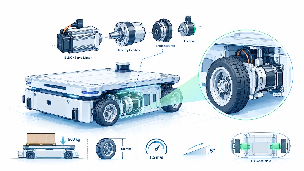
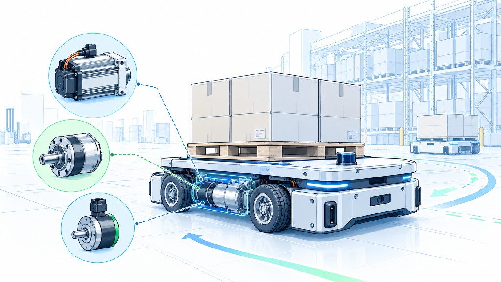
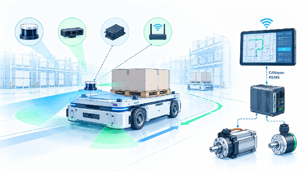
For most warehouse and factory mobile robots, a practical drive module contains several elements: an electric motor, reduction gearbox, encoder, motor controller or servo drive, wheel or wheel hub, and often an electromagnetic brake. A commercial integrated wheel drive may combine several of these functions in one package. Maxon, for example, describes its AGV wheel drive as a modular system built around a motor, gearhead and encoder, with brake, controller and wheel available as additions. Portescap likewise highlights the need for AGV wheel motors to provide continuous torque, acceleration torque and controlled stopping while remaining compact and efficient. These examples reflect a broader industry reality: the motor cannot be selected independently from the gearbox, feedback device, brake, controller and wheel.
This guide explains a practical engineering workflow for selecting an AMR drive motor or motor for AGV applications. It is intended for AGV/AMR manufacturers, warehouse-automation integrators, robotics engineers, purchasing teams and OEMs evaluating BLDC, servo and geared-motor solutions.
Important engineering note: The equations and worked example in this article are sizing tools, not a substitute for vehicle-level validation. Final selection should be checked against the actual motor torque-speed curve, gearbox limits, tire or wheel data, battery voltage range, controller current limits, thermal tests, braking requirements and the applicable machinery/vehicle safety standards.
Why AGV and AMR Motor Selection Is More Difficult Than It Looks
The traction motor experiences several operating conditions during a normal mission. It may start with a heavy payload, accelerate from zero, cruise efficiently for tens of meters, decelerate regeneratively, make repeated low-speed turns, cross expansion joints, climb a ramp, stop on a slope, wait while holding a load, and repeat the sequence hundreds of times per shift.
The worst torque condition and the worst thermal condition are often not the same condition. Peak torque may occur for only one or two seconds during acceleration on a slope. Continuous heating may instead be dominated by repeated cruising, steering corrections and low-speed operation. This distinction is essential because motors and drives usually have separate continuous and peak ratings.
A useful selection process therefore asks four different questions:
-
What wheel torque is required at steady state? This is mainly determined by rolling resistance and grade.
-
What peak wheel torque is required? Acceleration, obstacles, starting resistance and design margin can dominate this value.
-
What wheel speed is required? Vehicle speed and wheel diameter set the wheel rpm directly.
-
Can the motor and gearbox deliver both torque and speed throughout the real duty cycle without overheating or exceeding current, voltage or mechanical limits?
If only one of these questions is answered, the motor can still be wrong.
The Inputs You Should Define Before Contacting a Motor Supplier
Before asking for a motor recommendation, prepare a drive-system requirement sheet. A supplier can give a much more useful answer when the application is defined numerically rather than described only as “a 500 kg AGV.”
| Input | Symbol / Unit | Why It Matters |
|---|---|---|
| Maximum vehicle + payload mass | m, kg | Sets grade, rolling and acceleration force |
| Number of driven wheels | N | Determines force/torque sharing per drive |
| Drive-wheel diameter | D, m or mm | Converts tractive force into wheel torque and speed into rpm |
| Maximum vehicle speed | v, m/s | Determines wheel rpm and motor rpm after gearing |
| Target acceleration | a, m/s² | Major contributor to peak torque |
| Maximum grade | θ, degrees or % | Can dominate continuous traction torque |
| Rolling resistance coefficient | Crr | Represents wheel/floor losses |
| Gear ratio | i | Trades motor speed for wheel torque |
| Gearbox efficiency | ηg | Reduces usable output torque/power |
| Battery nominal/min/max voltage | VDC | Determines motor winding/controller operating point |
| Duty cycle | % / mission profile | Determines RMS torque and thermal loading |
| Required stopping/holding behavior | — | Determines brake and safety architecture |
| Encoder requirement | PPR / CPR / absolute bits | Affects speed loop, odometry and position feedback |
| Communication | CANopen, RS485, EtherCAT, etc. | Affects controller integration |
| Environmental protection | IP rating | Affects dust/water resistance and enclosure choice |
| Ambient temperature | °C | Changes thermal margin and component ratings |
A purchasing specification should also state dimensional limits, output-shaft geometry, connector preference, cable length, expected annual quantity, required certifications and whether the motor, gearbox, encoder and brake should be supplied as a matched assembly.
Start at the Wheel: Calculate the Required Tractive Force
The cleanest way to size an AGV drive is to begin with the forces acting on the complete vehicle. The motor is selected later, after the wheel and gearbox requirements are known.
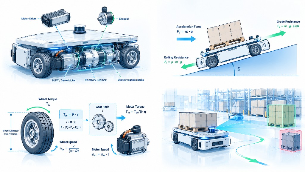
For a simplified longitudinal model, the total required tractive force can be written as:
F_total = F_roll + F_grade + F_acc + F_other
where:
-
F_roll is rolling resistance,
-
F_grade is the force required to climb a slope,
-
F_acc is acceleration force,
-
F_other represents additional losses or application-specific forces such as seals, drivetrain drag, scrub during steering, floor joints or a design allowance.
Rolling resistance
A commonly used first-order model is:
F_roll = Crr × m × g × cos(θ)
For small warehouse slopes, cos(θ) is close to 1, so engineers sometimes use F_roll ≈ Crr × m × g for preliminary sizing.
Rolling resistance deserves more attention than it usually receives. It depends on wheel material, wheel diameter, floor hardness and roughness, load, temperature, alignment and deformation. Published engineering references show that rolling resistance can vary substantially with the wheel/ground combination. For a design that must work reliably, use measured push-force or coast-down data from the real wheel and floor whenever possible rather than treating a generic coefficient as a guaranteed value.
In this article's worked example, Crr = 0.02 is used as an explicit engineering assumption for a hard indoor surface. It is not presented as a universal AGV value. If testing shows Crr = 0.03, 0.04 or higher, the calculation should simply be rerun with the measured value.
Grade force
The gravitational force parallel to a slope is:
F_grade = m × g × sin(θ)
This term becomes important surprisingly quickly. A 5° grade is about 8.75%, and a 500 kg vehicle requires more than 400 N merely to counter gravity on that incline. That force exists before acceleration and rolling resistance are added.
If the specification gives grade in percent rather than degrees:
grade % = 100 × rise / run
and the angle can be obtained from:
θ = arctan(grade / 100)
Do not casually treat “5% grade” and “5° grade” as the same condition. Five degrees corresponds to approximately 8.75% grade and therefore requires significantly more traction.
Acceleration force
For straight-line acceleration:
F_acc = m × a
A 500 kg vehicle accelerating at 0.5 m/s² requires 250 N of additional tractive force. At 1.0 m/s², that becomes 500 N. This is why two AGVs with the same mass and maximum speed can require very different peak motor torque.
The simple equation above ignores rotational inertia of wheels, rotors and gears. For preliminary sizing this may be acceptable, but high-dynamic systems should include reflected rotational inertia or apply a justified engineering allowance.
Convert Tractive Force into Wheel Torque
Once total tractive force is known, calculate the torque at the drive wheel:
T_wheel,total = F_total × r
where r is the effective rolling radius of the drive wheel.
If two identical drive wheels share traction equally:
T_wheel,per drive = F_total × r / 2
For four identical traction drives, divide by four only if the mechanical layout and control system can actually share the load approximately equally. Real vehicles can experience unequal wheel loading because of center-of-gravity location, chassis compliance, floor unevenness and acceleration load transfer. A nominal “four-motor” design should therefore not automatically assume perfect 25% load sharing under every condition.
Wheel torque is the most useful intermediate result because it separates vehicle physics from motor technology. Whether the final drive uses a BLDC motor, servo motor or another traction motor, the wheel still needs essentially the same mechanical torque for the same vehicle condition.
Convert Vehicle Speed into Wheel Speed
Wheel speed follows directly from linear speed and wheel circumference:
n_wheel = v / (π × D) × 60
where:
-
n_wheel is wheel speed in rpm,
-
v is vehicle speed in m/s,
-
D is effective wheel diameter in meters.
A 200 mm wheel moving at 1.5 m/s rotates at approximately 143 rpm. That is much slower than the efficient operating speed of many compact BLDC and servo motors, which is one reason reduction gearboxes are common in AGV/AMR traction drives.
A larger wheel reduces wheel rpm at a given vehicle speed but increases required wheel torque because torque equals force multiplied by radius. A smaller wheel does the opposite. Wheel diameter is therefore part of the transmission ratio, not just a packaging choice.
Select the Gear Ratio from Both Speed and Torque
A gearbox converts a relatively high-speed, lower-torque motor output into lower-speed, higher-torque wheel output.
For a reduction ratio i defined as motor speed divided by output speed:
n_motor = i × n_wheel
and, allowing for gearbox efficiency:
T_motor = T_wheel / (i × ηg)
A common mistake is to choose a ratio only from torque. Another is to choose it only from desired motor speed. Both constraints must be satisfied simultaneously.
Suppose a 200 mm wheel needs 143 rpm at maximum vehicle speed. With a 10:1 gearbox, the motor runs near 1,432 rpm. With 15:1, it runs near 2,149 rpm. If the chosen motor has a strong continuous operating region around 2,000–3,000 rpm, the higher ratio may be attractive because it reduces motor torque. But the gearbox itself must accept the wheel torque, shock load and radial load, and the motor must still have sufficient speed margin as battery voltage falls.
Gearbox efficiency matters
No gearbox is perfectly efficient. Planetary gearboxes can offer a useful combination of compactness, torque density and relatively low backlash, while worm gearboxes may offer packaging or self-locking advantages in some applications but can have lower efficiency. The exact value should come from the selected gearbox datasheet and should be evaluated across load and speed when the application is demanding.
If a gearbox is 90% efficient, 10% of the mechanical power passing through it is lost as heat at the evaluated operating point. Ignoring this loss produces an optimistic motor torque requirement.
Backlash and AGV traction
Backlash is not always as critical in a traction drive as it is in a precision CNC axis, but it can still affect low-speed reversal, velocity control, docking behavior and odometry. Mobile robots that repeatedly reverse direction or perform precise docking can benefit from low-backlash gearing and high-resolution feedback.
FRANK HU MOTOR's illustrates the broader principle of combining the motor with feedback and gearing as one motion subsystem rather than evaluating each part in isolation.
Motor Power: Useful, but Not the First Number to Select
Mechanical power is:
P = F × v
or equivalently:
P = T × ω
At the wheel, power depends on tractive force and vehicle speed. Gear reduction changes torque and speed but, aside from losses, does not change mechanical power.
This is why selecting a motor only by wattage is dangerous. Two 500 W motors can have very different torque-speed curves. One may deliver the required torque at 1,800 rpm continuously, while another may only reach 500 W at a much higher speed that the selected gearbox cannot use.
The correct procedure is:
-
calculate torque and speed at the wheel;
-
select a candidate gearbox ratio;
-
calculate required motor torque and motor speed;
-
compare the resulting operating points with the manufacturer's continuous and peak torque-speed curves;
-
check thermal duty, drive current and voltage limits.
Rated power is then a useful consistency check, not the sole selection criterion.
Worked Example: 500 kg AGV, 200 mm Wheel, 1.5 m/s, 5° Grade, Dual Drive, 48V Battery
Consider an AGV or AMR with the following requirements.
| Parameter | Design Value |
|---|---|
| Maximum total mass, including payload | 500 kg |
| Drive configuration | 2 driven wheels |
| Drive-wheel diameter | 200 mm |
| Effective wheel radius | 0.10 m |
| Maximum vehicle speed | 1.5 m/s |
| Maximum grade | 5° (about 8.75%) |
| Battery | 48 V nominal |
| Rolling resistance coefficient used for example | 0.02 |
| Target acceleration used for peak calculation | 0.5 m/s² |
| Gearbox efficiency used for example | 90% |
| Gravity | 9.81 m/s² |
The acceleration and rolling-resistance values are explicit design assumptions so that the calculation can be audited. A real OEM should replace them with its own specification and measured data.
Step 1: Rolling resistance force
F_roll = Crr × m × g × cos(θ)
= 0.02 × 500 × 9.81 × cos(5°)
≈ 97.7 N
Step 2: Grade force
F_grade = m × g × sin(θ)
= 500 × 9.81 × sin(5°)
≈ 427.5 N
Step 3: Continuous tractive force while climbing at steady speed
For this simplified example:
F_cont = F_roll + F_grade
= 97.7 + 427.5
≈ 525.2 N
The word “continuous” here means the steady climbing operating point used for sizing. Whether the motor can thermally sustain this point depends on how long the vehicle actually remains on the grade, motor cooling and the complete duty cycle.
Step 4: Acceleration force
F_acc = m × a
= 500 × 0.5
= 250 N
Step 5: Peak tractive force for simultaneous climb and acceleration
F_peak = F_cont + F_acc
= 525.2 + 250
≈ 775.2 N
This is a deliberately demanding combined condition. If the vehicle controller limits acceleration on ramps, the real peak requirement may be lower. Conversely, floor joints, caster scrub or a higher measured rolling resistance can increase it.
Step 6: Continuous wheel torque per driven wheel
For two equally loaded drive wheels:
T_wheel,cont = F_cont × r / 2
= 525.2 × 0.10 / 2
≈ 26.3 N·m per drive wheel
Step 7: Peak wheel torque per driven wheel
T_wheel,peak = F_peak × r / 2
= 775.2 × 0.10 / 2
≈ 38.8 N·m per drive wheel
These wheel-torque numbers are the key mechanical requirements before additional design margin is applied.
Step 8: Wheel speed at 1.5 m/s
n_wheel = v / (π × D) × 60
= 1.5 / (π × 0.20) × 60
≈ 143 rpm
Step 9: Compare candidate gearbox ratios
Using 90% gearbox efficiency:
| Gear Ratio | Motor Speed at 1.5 m/s | Motor Torque for Steady 5° Climb | Motor Torque for Climb + 0.5 m/s² Accel | Mechanical Power per Motor at Continuous Point |
|---|---|---|---|---|
| 10:1 | 1,432 rpm | 2.92 N·m | 4.31 N·m | 438 W |
| 12:1 | 1,719 rpm | 2.43 N·m | 3.59 N·m | 438 W |
| 15:1 | 2,149 rpm | 1.95 N·m | 2.87 N·m | 438 W |
The power remains approximately the same because the gearbox trades speed for torque; only losses change the relationship. The ratio changes where the motor operates on its torque-speed curve.
Step 10: Add engineering margin
The calculated values are not yet a purchase specification. A practical design needs margin for uncertainties such as wheel wear, floor variation, gearbox efficiency tolerance, battery sag, load distribution, manufacturing variation and temperature.
For illustration, applying a 1.25 torque margin to the 15:1 case gives:
-
design continuous motor torque ≈ 2.44 N·m;
-
design peak motor torque ≈ 3.59 N·m;
-
maximum motor speed ≈ 2,149 rpm at 1.5 m/s.
This does not mean that any motor labeled 2.5 N·m is suitable. The candidate must deliver roughly that continuous torque at about 2,150 rpm, not merely produce that torque at stall or at a much lower speed. Its drive must also supply the necessary phase current from the available DC bus.
Step 11: Estimate power class
At the continuous climbing point, mechanical wheel power for the whole vehicle is:
P_vehicle = F_cont × v = 525.2 × 1.5 ≈ 788 W
With two drives, that is about 394 W at each wheel. Accounting for 90% gearbox efficiency requires about 438 W mechanical motor output per motor at this operating point.
During the combined acceleration + grade condition:
P_peak,vehicle = 775.2 × 1.5 ≈ 1,163 W
or about 646 W mechanical motor output per motor after the assumed gearbox loss.
A sensible candidate may therefore fall in a nominal class above these calculated numbers—often around the several-hundred-watt to roughly 750 W or higher range per drive for this particular example—but the final answer must come from the motor's torque-speed curve, duty rating and thermal test. The nominal wattage alone is not sufficient evidence.
What Changes If the AGV Never Accelerates at Maximum Speed on the Maximum Grade?
Real motion profiles matter. The worked example intentionally combines a 5° grade, 0.5 m/s² acceleration and the maximum speed point to demonstrate a conservative calculation. Many vehicles will not command all three simultaneously.
If the control software limits speed and acceleration on ramps, the peak mechanical power can fall substantially even though low-speed torque remains high. This can allow a smaller motor or drive while retaining the necessary wheel torque through gearing.
The correct way to exploit this is not to remove margin casually. Define the vehicle's allowed speed/acceleration envelope and verify that the motion controller enforces it. Then size the motor against the actual worst permitted operating points.
BLDC Motor for AGV: Why It Is Often the Default Choice
A BLDC motor for AGV traction is popular because brushless motors can combine high efficiency, good power density, long service life, wide controllable speed range and relatively low maintenance. There are no mechanical commutator brushes to replace, which is valuable for mobile robots expected to operate for long hours.
Portescap's AGV application guidance emphasizes compactness, efficiency, continuous torque, acceleration capability and controlled stopping, and lists brushless DC solutions among its AGV drive technologies. Maxon's AGV wheel-drive architecture similarly integrates motor, gearbox and encoder, with brake and controller options. These are not proof that BLDC is always the correct choice, but they show why brushless geared drives are common in modern mobile robotics.
A BLDC traction system typically includes:
-
three-phase brushless motor;
-
Hall sensors and/or encoder;
-
field-oriented-control or trapezoidal motor controller;
-
reduction gearbox;
-
electromagnetic brake if required;
-
wheel or wheel hub;
-
CAN/CANopen, RS485 or another command/diagnostic interface.
For a 48V AGV motor, the controller should be selected for the battery's actual maximum voltage, not just the “48 V” label. Battery chemistry and state of charge determine the real bus range. Regenerative braking can also raise DC-bus voltage, so overvoltage handling, battery acceptance of regenerative current and braking strategy must be engineered together.
When an AGV Servo Motor Makes Sense
A servo motor is attractive when the application needs high dynamic response, precise closed-loop speed/torque control, strong overload capability, high-resolution feedback or tightly coordinated motion.
The distinction between a “BLDC motor” and a “servo motor” can become blurred because many servo systems use permanent-magnet brushless motors. In practice, “servo” usually describes the complete closed-loop motor-drive-feedback system and its control capabilities rather than only the electromagnetic motor construction.
An AGV servo motor may be justified when:
-
acceleration and deceleration are aggressive;
-
the vehicle must track velocity very precisely;
-
docking or synchronized wheel control is demanding;
-
high-resolution encoder feedback is required;
-
the controller needs torque mode or sophisticated motion profiles;
-
load variation is large;
-
diagnostic visibility and fault handling are important;
-
the OEM already uses a standardized servo communication architecture.
For a deeper technology comparison, see FRANK HU MOTOR's and . Although those articles cover broader automation applications, the same principles—dynamic torque, feedback, speed range, inertia and system cost—also matter in mobile robots.
Are Stepper Motors Suitable for AGV or AMR Traction?
Stepper motors can work in small, low-speed mobile platforms, especially when cost is important and the speed range is modest. Closed-loop steppers can add feedback and fault detection. However, traction duty often favors BLDC or servo solutions because AGVs commonly need efficient continuous operation over a broad speed range.
A stepper's holding torque number can be misleading for traction selection because holding torque is measured at zero speed. Available torque decreases as speed rises, and continuous current can create significant heat. A vehicle that must travel quickly for long periods should therefore be evaluated using the full dynamic torque-speed curve.
Closed-loop steppers can still be useful in specialized mobile platforms, steering actuators, lift mechanisms or auxiliary axes. FRANK HU MOTOR's explains why closed-loop stepper and servo decisions should be based on dynamic operating points rather than nameplate holding torque. The same engineering discipline applies to AGV subsystems.
24V vs 48V AGV Drive Systems
Voltage selection influences current, conductor size, controller design, motor winding and power distribution.
For the same electrical power, doubling bus voltage approximately halves current in the idealized relationship:
P = V × I
A 1 kW electrical load would theoretically draw about 41.7 A at 24 V or 20.8 A at 48 V before efficiency and transient effects are considered. Lower current can reduce I²R losses and make cabling and switching easier at higher power levels.
This is one reason 48 V architectures are attractive for medium and larger AGVs/AMRs. However, “48 V” does not specify the complete electrical requirement. Engineers should define:
-
nominal battery voltage;
-
fully charged voltage;
-
minimum operating voltage under load;
-
allowable regenerative voltage;
-
controller undervoltage and overvoltage thresholds;
-
continuous and peak battery current;
-
fuse/contactors and cable ratings;
-
EMC and grounding architecture.
A motor winding optimized for 24 V may not be the best winding for 48 V operation even if the controller can technically run both. Back-EMF, winding resistance, inductance, speed requirement and current limit should be matched as a system.
Continuous Torque, Peak Torque and RMS Torque
Motor catalogs commonly specify continuous torque and a higher short-duration peak torque. AGV designers should understand what each means.
Continuous torque is the torque the motor can produce under specified thermal conditions without exceeding its temperature limit. It is strongly affected by ambient temperature, mounting, airflow and motor construction.
Peak torque is available only for a limited duration and is constrained by current, magnetic saturation, drive capability, winding temperature and mechanical limits.
For repeated mission cycles, RMS torque is a useful thermal sizing quantity:
T_RMS = sqrt[(T1²t1 + T2²t2 + ... + Tn²tn) / (t1 + t2 + ... + tn)]
This approach captures the heating effect of a cycle more realistically than simply selecting the maximum torque as a continuous requirement.
For example, a robot may accelerate at high torque for 2 seconds, cruise at moderate torque for 20 seconds, decelerate for 2 seconds and wait for 10 seconds. The peak torque determines short-term capability, while RMS torque helps evaluate thermal loading. Final thermal verification should still follow the motor manufacturer's data and preferably include vehicle testing.
Do Not Ignore Traction: Motor Torque Is Useless If the Wheel Slips
The maximum usable tractive force is limited by wheel/floor friction and normal load. A simplified traction limit is:
F_traction,max ≈ μ × N
where μ is the friction coefficient and N is normal force on the driven wheel or wheels.
If the calculated drive force exceeds available traction, installing a larger motor will not solve the problem. The wheel will slip first.
This is especially important for differential-drive AGVs with only two driven wheels and additional casters. Payload position can shift normal force away from the drive wheels. Wet floors, dust, oil, wheel wear or polished surfaces can reduce traction further.
The drive design should therefore check both sides of the problem:
-
motor/gearbox capability: can the drive produce the required force?
-
tire/floor traction capability: can the vehicle transmit that force without slipping?
This also affects braking. A theoretically powerful regenerative or mechanical brake cannot decelerate the vehicle faster than the tire-floor interface can support without slip.
Encoder Selection: Motor Commutation, Velocity Control and Odometry Are Different Jobs
AGV designers sometimes ask only, “Does the motor have an encoder?” A better question is, “What information does the vehicle need from the encoder, and where should it be measured?”
A motor encoder can support:
-
rotor position or commutation;
-
motor velocity control;
-
servo position loop;
-
stall/fault detection;
-
estimated wheel travel after the gearbox.
But an encoder mounted on the motor does not directly measure wheel motion after gearbox backlash, tire compression or wheel slip. For high-quality odometry, system designers may combine drive encoders with other sensors such as inertial measurement, lidar, cameras or additional wheel feedback.
Encoder resolution should be considered after gearing. If a motor encoder produces a high number of counts per revolution and the gearbox has a 15:1 ratio, the effective count density per wheel revolution can become very high. That can improve low-speed velocity estimation, but controller bandwidth, signal interface and processing capability must also be appropriate.
For motion-system context, FRANK HU MOTOR offers encoder-equipped motor configurations in its . A product example such as the also illustrates how encoder specifications should be treated as a defined subsystem parameter rather than a generic “closed loop” label.
Brake Selection: Parking, Emergency Behavior and Power-Off Holding
An electromagnetic brake on an AGV motor is often a holding brake, not automatically a certified emergency brake. This distinction matters.
A brake may be required to:
-
hold the vehicle on a slope when power is removed;
-
prevent creep during loading/unloading;
-
provide a defined state after an emergency stop;
-
support maintenance or transport procedures.
Brake torque should be referred to the correct shaft. A brake mounted on the motor side benefits from gearbox multiplication at the wheel, but gearbox backlash and failure modes must be considered. A wheel-side brake sees a different torque requirement.
The safety function should be determined by the vehicle risk assessment rather than by assuming that “motor brake = safe stop.” ISO 3691-4:2023 covers safety requirements and verification for driverless industrial trucks and explicitly includes AGVs and AMRs within its scope. As of September 2026, ISO also lists a new draft revision under development. For machinery risk assessment more generally, ISO 12100 remains a foundational reference, while ISO 13849-1:2023 provides methodology for safety-related parts of control systems.
Useful references: , , and .
CANopen, RS485 and Drive Communication
The communication interface is not just a connector choice. It affects commissioning, diagnostics, synchronization, fault handling and how easily a vehicle controller can command multiple drives.
CANopen and CiA 402
For CANopen motion systems, CiA 402 is especially relevant. CAN in Automation describes CiA 402 as a device profile for drives and motion control. It standardizes drive behavior including a finite state automaton, controlword/statusword behavior and operating modes for drive systems. Parts of the profile are standardized in IEC 61800-7.
For an AGV OEM, a well-implemented CiA 402 drive can simplify software architecture because the host controller can interact with a familiar state model and standardized motion objects. However, CiA itself notes that implementations can support different subsets of optional functions, so “CANopen/CiA 402 compatible” should be verified against the exact required modes and objects rather than accepted as a complete interoperability guarantee.
See the official .
RS485
RS485 is a physical-layer standard commonly used with vendor protocols or protocols such as Modbus RTU. It can be a practical, cost-effective choice for configuration, diagnostics and lower-bandwidth command systems. But the designer should define the actual application protocol, update rate, fault behavior and synchronization needs. Saying only “RS485 required” is incomplete.
What to specify to the motor/drive supplier
State whether you need:
-
velocity mode, torque mode, position mode or combinations;
-
CANopen and specific CiA 402 modes;
-
CAN bitrate and connector/pinout;
-
RS485 protocol and register map;
-
digital enable, brake output and fault output;
-
STO or other safety-related interfaces if required by the architecture;
-
regenerative braking support;
-
parameter storage and field firmware update capability;
-
diagnostic values such as current, temperature, voltage and fault history.
IP Rating and Environmental Protection
Warehouse robots may appear to operate in a clean environment, but motors near the floor encounter dust, fibers, cleaning water, condensation and debris. Factory AGVs can face metal dust, coolant mist or temperature variation.
The familiar IP code is defined by IEC 60529, which classifies degrees of protection provided by electrical enclosures. The correct IP target should be selected from the actual environment and enclosure architecture, not copied from another robot.
Official reference: .
When specifying an AGV drive, clarify whether the IP rating applies to:
-
the bare motor;
-
motor plus encoder;
-
motor plus gearbox;
-
connectors and cable exits;
-
the complete wheel-drive assembly.
A motor rated IP65 does not make an open connector or unsealed gearbox IP65.
Gearbox Selection Beyond the Ratio
The ratio is only the beginning. A geared motor for mobile robot applications should be checked for:
-
rated output torque;
-
emergency/peak output torque;
-
input speed;
-
radial and axial output-shaft loads;
-
bearing life;
-
backlash;
-
efficiency;
-
lubrication life;
-
noise;
-
shock load;
-
mounting orientation;
-
temperature range.
Wheel loads can be particularly demanding because the gearbox output bearing may see radial force from vehicle weight in addition to drive torque. If the wheel is mounted directly to the gearbox output, verify that the gearbox bearing is designed for the resulting overhung load. Otherwise, use an external wheel bearing so the gearbox transmits torque without carrying the full vehicle load.
For high-volume AGV designs, integrating the motor, planetary gearbox, encoder, brake and wheel support can reduce assembly complexity and wiring, but it also makes serviceability and supplier qualification more important.
Thermal Design and Duty Cycle
AGV motors often operate inside compact chassis spaces with limited airflow. A motor that performs well on an open test bench may run hotter inside a sealed robot.
Thermal design should consider:
-
ambient temperature inside the chassis;
-
motor mounting surface and heat conduction;
-
controller heat near the motor;
-
repeated acceleration current;
-
low-speed operation, where some cooling mechanisms are less effective;
-
gearbox losses;
-
brake coil heating while released or engaged, depending on brake design;
-
dust filters and enclosure ventilation;
-
worst-case mission duration.
The final prototype should log motor temperature, drive temperature, DC-bus voltage and current during a representative worst-case mission. If the system reaches thermal limits only after 45 minutes, a five-minute bench test will not reveal the problem.
Battery Runtime and Motor Efficiency
Motor efficiency affects how much of the battery's stored energy becomes useful wheel power. But runtime cannot be predicted from motor efficiency alone.
A realistic energy model includes:
-
traction energy during acceleration and cruise;
-
grade work;
-
rolling losses;
-
gearbox losses;
-
motor and inverter losses;
-
steering actuators;
-
lift/conveyor mechanisms;
-
computers, lidar, cameras and communications;
-
safety sensors;
-
DC/DC converters;
-
idle consumption;
-
regenerative energy actually accepted by the battery.
For a first estimate:
Electrical energy ≈ ∫ P_electrical dt
over the complete mission.
A highly efficient BLDC drive can materially improve runtime in a robot that spends much of its shift moving, but a warehouse AMR that spends long periods waiting may have a surprisingly large share of energy consumed by computing and sensors. Measure the whole vehicle.
Regenerative Braking: Useful but Not Free Energy
BLDC and servo drives can often return energy to the DC bus during deceleration. Whether that energy reaches the battery depends on the controller and battery system.
Questions to resolve include:
-
Can the motor controller regenerate into the DC bus?
-
Can the battery/BMS accept charging current at the present state of charge and temperature?
-
What happens when the battery is nearly full?
-
Is a braking resistor or other overvoltage strategy required?
-
What deceleration remains available if regeneration is limited?
-
How is the safety stop implemented independently of normal regenerative control where required?
Regeneration can improve efficiency in stop-and-go duty, but it should not be treated as guaranteed recovered energy in every operating state.
Differential Drive, Steering and Motor Matching
Many warehouse robots use two independently driven wheels with one or more passive casters. Steering is achieved by commanding different left and right wheel velocities.
This architecture makes motor matching and low-speed control important. Differences in wheel diameter, gearbox efficiency or velocity-loop tuning can cause heading error. Encoder feedback allows the controller to correct much of this behavior, while localization sensors correct accumulated odometry error at the vehicle level.
For a turn-in-place maneuver, wheel scrub and caster behavior can require more torque than straight-line rolling calculations predict. The effect depends strongly on chassis geometry, wheel material, caster placement and floor. Prototype measurement is therefore valuable: record current/torque during worst-case pivot turns with maximum payload.
Wheel Diameter Is a Motor-Selection Variable
Changing from a 160 mm to a 200 mm drive wheel is not a cosmetic change.
At the same vehicle force, the 200 mm wheel requires 25% more torque than the 160 mm wheel because radius increases from 80 to 100 mm. At the same vehicle speed, however, the larger wheel rotates 20% slower.
This trade can be useful. A larger wheel may cross floor joints more easily and reduce rolling resistance in some conditions, but it increases wheel torque and packaging height. A smaller wheel reduces torque but increases wheel rpm and can perform worse over irregular floors.
Always freeze the effective rolling diameter before finalizing the gearbox ratio.
Safety Standards Should Influence the Drive Architecture Early
AGV/AMR safety cannot be added after the traction system is finished. The drive architecture affects stopping distance, brake behavior, fault detection and control-system diagnostics.
The current published specifies safety requirements and verification for driverless industrial trucks and their systems and explicitly identifies AGVs and AMRs among the covered examples. ISO shows that a newer draft revision is under development in 2026, so manufacturers designing products with a long certification horizon should monitor the transition.
provides general machinery risk-assessment and risk-reduction principles. addresses the design and integration methodology for safety-related parts of control systems.
These standards do not tell you “use a 750 W motor.” Their relevance is architectural: the vehicle designer must identify hazards, define required safety functions and ensure that stopping, braking, control and fault-response behavior meet the required risk-reduction strategy.
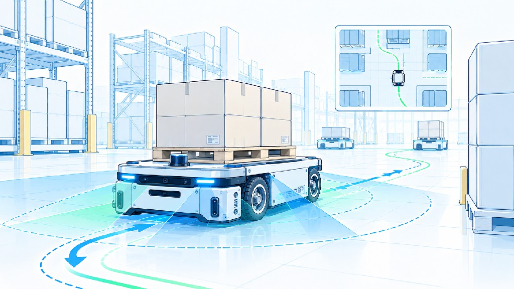
A Practical AGV/AMR Motor Selection Workflow
A robust commercial selection process can be organized into the following sequence.
1. Define the maximum operating mass
Use the real maximum vehicle mass including battery, attachments and payload. Do not size from payload alone.
2. Define the complete motion envelope
Specify maximum speed, normal cruise speed, acceleration, deceleration, maximum grade, ramp transition and whether acceleration on the maximum grade is permitted.
3. Define the wheel and floor
Specify drive-wheel diameter, tread material, hardness if relevant, floor material and expected contamination. Measure rolling resistance when possible.
4. Calculate continuous and peak wheel force
Include rolling resistance, grade and acceleration separately so that assumptions remain visible.
5. Check traction limit
Verify that driven-wheel normal load and wheel/floor friction can transmit the required force.
6. Calculate wheel torque and wheel rpm
These become the mechanical interface requirements for each drive module.
7. Select candidate gearbox ratios
Choose ratios that place the motor in a useful speed range while meeting wheel torque. Include gearbox efficiency.
8. Compare actual torque-speed curves
Check continuous and peak motor torque at the calculated rpm. Do not substitute stall torque or holding torque.
9. Check gearbox mechanical limits
Verify continuous/peak output torque, radial load, input speed, backlash and life.
10. Check the electrical system
Verify battery min/max voltage, controller current, motor winding, regenerative behavior, fusing and cabling.
11. Define encoder and communications
Specify feedback resolution, signal type, CANopen/CiA 402 or RS485 requirements, control modes and diagnostic data.
12. Define brake and safety behavior
Determine power-off holding, slope parking, emergency behavior and safety-related control requirements through the vehicle risk assessment.
13. Calculate RMS duty and thermal margin
Use the real mission profile rather than assuming the peak point is continuous.
14. Prototype and instrument the vehicle
Measure current, bus voltage, motor/drive temperature, wheel speed and fault behavior at maximum payload.
15. Validate worst-case conditions
Test ramps, low battery, hot ambient, worn wheels, repeated starts, pivot turns and emergency stopping as applicable.
Selection Matrix: Which Motor Architecture Fits Which AGV/AMR?
| Application Profile | Likely Drive Direction | Why |
|---|---|---|
| Small indoor AMR, light payload, moderate speed | Compact geared BLDC | Efficient, low maintenance, compact |
| Medium warehouse AMR, long duty, 24/48V battery | Geared BLDC + encoder | Strong balance of efficiency, control and cost |
| Heavy AGV, high acceleration, demanding velocity control | Servo/BLDC servo + planetary gearbox | Higher dynamic capability and closed-loop control |
| Precision docking / coordinated wheel motion | Servo-class drive with high-resolution encoder | Better velocity/position feedback and diagnostics |
| Small low-speed auxiliary mobile mechanism | Closed-loop stepper may be viable | Cost-effective feedback at modest speed |
| Harsh factory environment | Sealed BLDC/servo geared drive | Better environmental protection and service life |
This matrix is a starting point, not a substitute for calculations. A well-sized BLDC system can outperform a poorly sized servo system, and a servo system can justify its higher cost when dynamics and diagnostics create real machine value.
Common AGV Motor Selection Mistakes
Selecting by vehicle weight only
“500 kg AGV motor” is not a complete specification. A flat-floor robot at 0.8 m/s and a 5°-grade robot at 1.5 m/s are different machines.
Selecting by rated watts only
Power does not tell you whether the motor can produce the required torque at the required rpm.
Using holding torque for a traction motor
Holding torque is a zero-speed stepper specification and does not describe high-speed continuous traction capability.
Ignoring minimum battery voltage
A drive that works at a fully charged battery may lose high-speed torque as the bus voltage falls.
Ignoring gearbox efficiency
This understates required motor torque and heat.
Assuming equal load sharing
Two or four motors do not automatically carry identical loads in the real chassis.
Forgetting radial wheel load
A gearbox output bearing may fail even when its torque rating appears adequate.
Treating the encoder as perfect odometry
Motor rotation does not reveal wheel slip.
Treating a holding brake as a complete safety function
Brake selection must be integrated with the risk assessment and stop architecture.
Failing to test pivot turns
Differential-drive scrub can create high current at low speed even when straight-line calculations look comfortable.
What Data Should You Send FRANK HU MOTOR for an AGV/AMR Drive Recommendation?
For a useful engineering discussion, provide the following application data in the first inquiry:
| Required Information | Example |
|---|---|
| Vehicle type | Warehouse AMR, differential drive |
| Maximum total mass | 500 kg |
| Number of drive wheels | 2 |
| Wheel diameter | 200 mm |
| Maximum speed | 1.5 m/s |
| Acceleration | 0.5 m/s² |
| Maximum grade | 5° |
| Floor | Smooth indoor concrete/epoxy |
| Battery | 48 V nominal, include min/max voltage |
| Target duty | 16 h/day, mission profile if available |
| Gearbox preference | Planetary / integrated wheel drive |
| Encoder | Incremental/absolute, required resolution |
| Brake | Power-off holding brake required/not required |
| Communication | CANopen/CiA 402, RS485, other |
| IP requirement | e.g. IP54/IP65 target for complete assembly |
| Mechanical envelope | Max diameter/length, shaft/wheel mounting |
| Annual volume | Prototype quantity + forecast |
FRANK HU MOTOR can then evaluate whether the project is best served by a geared BLDC motor, servo-class drive, encoder-equipped motor, brake-equipped assembly or a customized motor/gearbox configuration. The company's broader motion-control portfolio includes stepper, closed-loop stepper, BLDC/DC, servo, encoder and gearbox solutions, which is useful when the AGV also contains lift, steering, conveyor or positioning axes with different requirements from traction.
For engineers comparing motor families across machine types, FRANK HU MOTOR's , , and provide additional background on torque-speed behavior, feedback and system sizing.
Procurement Checklist for a 48V AGV Motor and Gearbox
Before releasing a drive to production, the engineering and procurement teams should jointly confirm:
-
motor continuous torque at required motor rpm;
-
motor peak torque and allowed peak duration;
-
continuous and peak phase/DC current;
-
nominal, minimum and maximum DC-bus voltage;
-
no-load and loaded maximum speed;
-
torque-speed curve at the intended voltage;
-
gearbox ratio and efficiency;
-
gearbox continuous and emergency torque;
-
output radial/axial load rating;
-
backlash;
-
encoder type, resolution and electrical interface;
-
brake voltage, torque and duty;
-
controller command modes;
-
CANopen/CiA 402 object/mode support or RS485 protocol details;
-
connector and cable specification;
-
IP protection of the complete delivered assembly;
-
ambient/storage temperature;
-
vibration/shock requirements;
-
EMC and applicable compliance requirements;
-
life target and bearing/gearbox assumptions;
-
drawing, STEP model and wiring diagram;
-
production test criteria and traceability;
-
customization control for shaft, winding, cable and connector revisions.
This checklist prevents a common sourcing problem: two quotations may both say “48 V, 750 W geared BLDC,” while representing very different mechanical, electrical and integration capabilities.
Frequently Asked Questions
What motor is best for an AGV?
There is no universal best motor. For many warehouse AGVs and AMRs, a geared BLDC motor with encoder feedback is a strong starting architecture because it offers efficiency, long service life and a broad controllable speed range. Higher-dynamic systems may justify servo-class drives. The final choice must be based on wheel torque, motor speed, duty cycle, voltage, gearbox, feedback and safety requirements.
How do I calculate AGV motor torque?
Calculate vehicle tractive force from rolling resistance, grade and acceleration. Multiply total force by wheel radius to obtain total wheel torque, then divide appropriately among driven wheels. Finally divide wheel torque by gearbox ratio and gearbox efficiency to obtain motor torque.
How much motor power does a 500 kg AGV need?
Weight alone is insufficient. In the worked example in this article—a 500 kg vehicle, 200 mm wheels, 1.5 m/s, 5° grade, dual drive and assumed Crr of 0.02—the vehicle needs about 788 W of mechanical wheel power merely to sustain maximum speed on the grade. With 90% gearbox efficiency, that is about 438 W mechanical motor output per drive. The combined grade-plus-acceleration point reaches about 646 W per motor in the example. A real selection needs additional margin and torque-speed/thermal verification.
Why use a gearbox on an AGV motor?
The wheel normally turns much slower than an efficient compact BLDC or servo motor. A gearbox allows the motor to run faster while multiplying torque at the wheel. The ratio must satisfy both top-speed and torque requirements.
Is a 48V AGV motor better than 24V?
Not automatically, but 48 V can reduce current for the same power and is often attractive as vehicle power increases. The complete battery voltage range, motor winding and controller must be matched.
Does an AGV need an encoder?
Most modern closed-loop traction systems benefit from encoder feedback for velocity control, commutation, diagnostics and odometry estimation. The required encoder type and resolution depend on the control architecture. Motor encoders do not directly detect wheel slip.
Does an AGV drive motor need a brake?
It depends on slope holding, power-off behavior, loading operations and the safety architecture. If a brake is required, specify its function and torque explicitly. Do not assume a standard motor holding brake alone satisfies all emergency-stop or safety requirements.
Is CANopen better than RS485 for an AMR drive motor?
They solve different integration needs. CANopen, particularly with CiA 402, offers a standardized motion-drive framework and is attractive for multi-drive control and diagnostics. RS485 can be economical and effective but requires a defined higher-level protocol. The best choice depends on the vehicle controller, update rate, diagnostic needs and existing software platform.
Final Engineering Recommendation
A reliable AGV motor selection starts with vehicle physics and ends with system validation. Begin with maximum mass, wheel diameter, speed, acceleration, grade and measured or defensible rolling resistance. Calculate wheel force, wheel torque and wheel rpm. Then choose a gearbox ratio that places the motor in a strong part of its torque-speed curve. Only after that should you choose motor wattage, winding, controller current and feedback.
For the 500 kg example developed here, the 200 mm wheel must turn at about 143 rpm to reach 1.5 m/s. With a 5° grade, Crr = 0.02 and dual drive, each wheel needs about 26.3 N·m for steady climbing. Adding 0.5 m/s² acceleration raises the calculated peak to about 38.8 N·m per wheel. With a 15:1, 90%-efficient gearbox, those values correspond to approximately 1.95 N·m continuous and 2.87 N·m peak at the motor before design margin, with motor speed around 2,149 rpm. A 1.25 torque margin raises the illustrative targets to about 2.44 N·m continuous and 3.59 N·m peak.
Those numbers are far more useful than simply asking for a “500 kg AGV motor.” They allow an engineer or supplier to compare real torque-speed curves, select a suitable gearbox, check current and voltage, calculate RMS duty and build a prototype that can be validated under worst-case conditions.
For commercial AGV/AMR projects, FRANK HU MOTOR can support motor and motion-system configuration around application requirements such as custom shafts and windings, encoder feedback, gearing, drive electronics and OEM/ODM integration. When requesting a recommendation, send the full vehicle data table rather than only payload and voltage. That gives the engineering team enough information to propose a drive system around measurable performance targets.
External technical references embedded in this guide: , , , , , , and