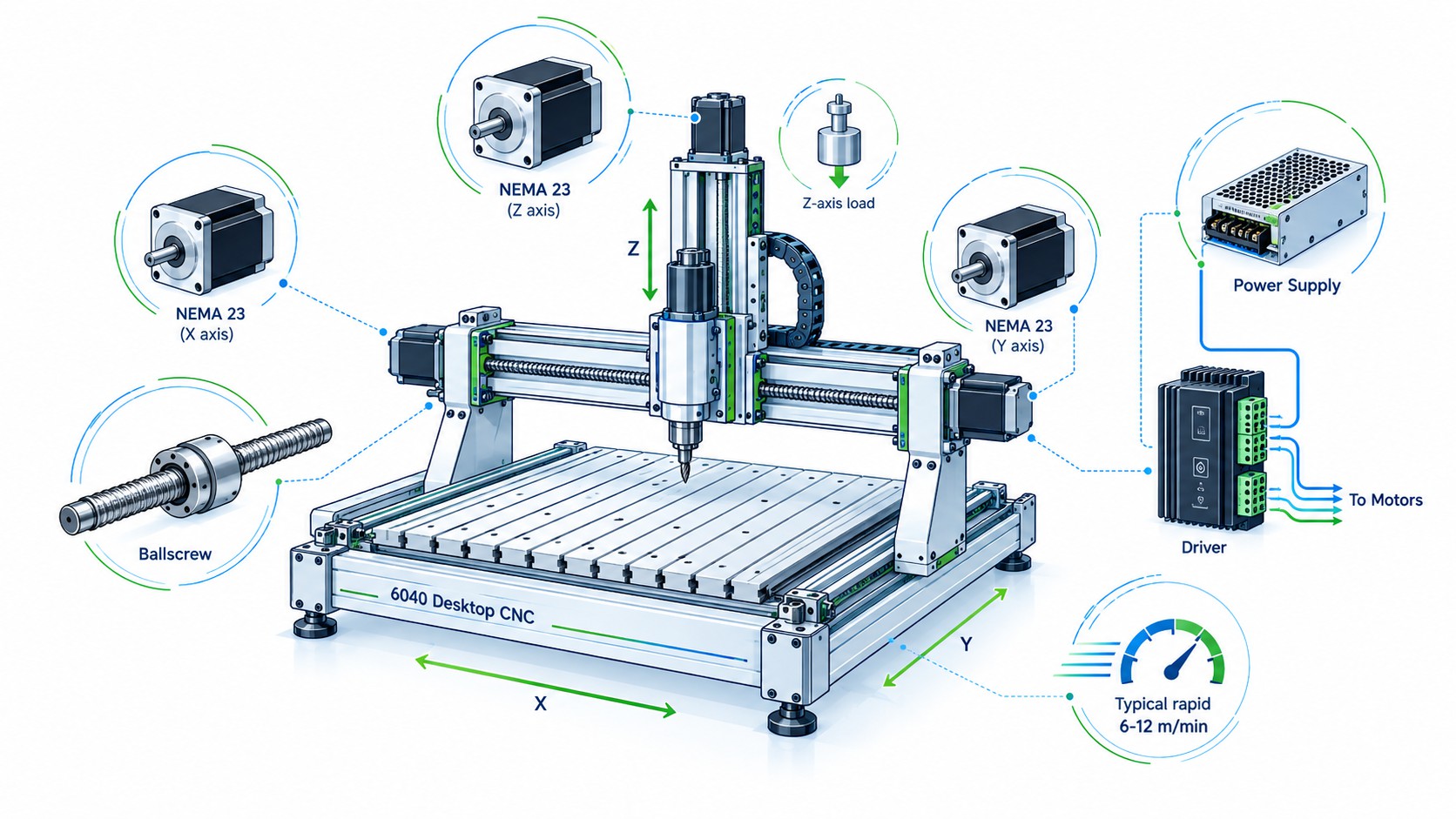
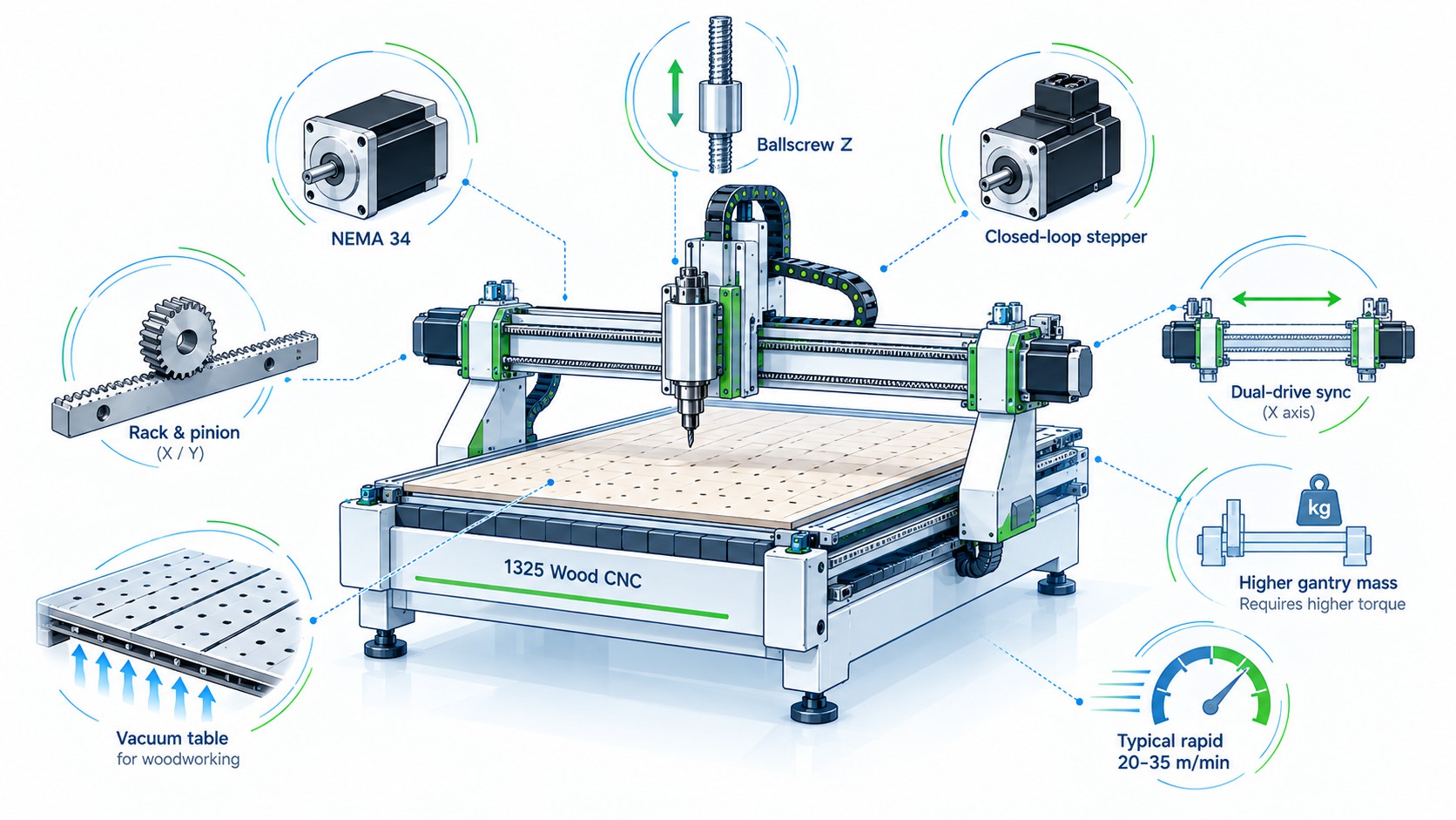
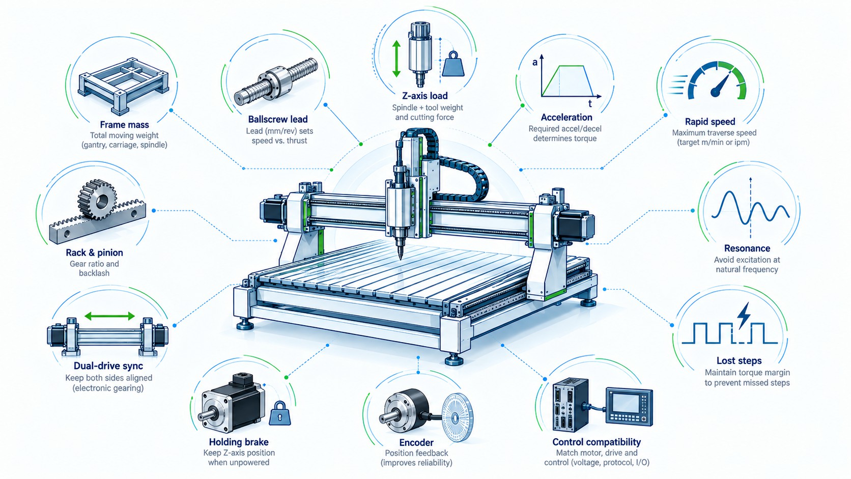
The correct motor depends on what the axis must accelerate, how the load is transmitted, how fast the axis must travel, how much cutting force it will see, whether gravity acts on the axis, and how much position risk the machine can tolerate. A compact 6040 desktop router moving a light aluminum gantry on ball screws may run extremely well with NEMA 23 stepper motors. A 1325 woodworking router with a wide gantry, rack-and-pinion drive, and two motors on the Y axis may need NEMA 34 motors or closed-loop steppers. A high-speed metal-cutting machine that must accelerate hard, maintain torque at high motor speed, synchronize multiple axes, and detect following error is usually a much better candidate for AC servo systems.
That is why a useful CNC motor selection guide must start with the machine rather than the motor label.
At , we supply stepper motors, closed-loop stepper systems, integrated motion products, servo motors and drives for CNC machinery and automation. This guide explains the engineering logic behind choosing among those technologies and gives three practical configurations that can be adapted to real machine designs.
Important engineering note: The numerical ranges in this guide are practical starting points for concept selection, not universal limits. Final sizing should always be verified with the actual motor torque-speed curve, axis mass, transmission efficiency, acceleration profile, duty cycle, drive voltage, thermal conditions and safety margin.
The Short Answer: Which Motor Type Fits Which CNC Machine?
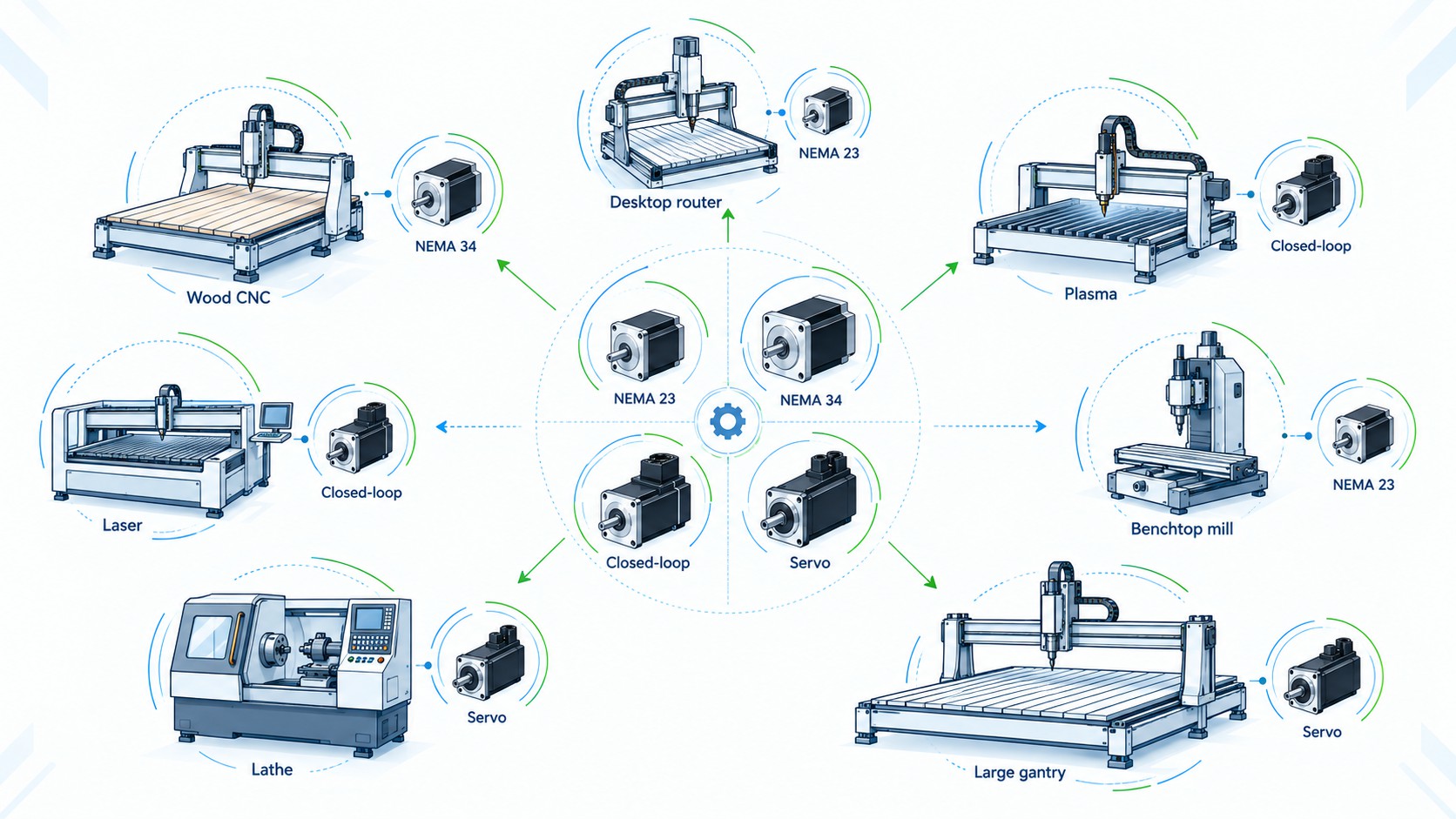
If you need a fast first-pass decision, the following table is a useful starting point.
| CNC machine type | Typical mechanical character | Practical first choice | When to move up |
|---|---|---|---|
| 3018 / 3020 / 3040 desktop CNC | Very light axes, short screws, low cutting force | NEMA 17 or compact NEMA 23 | Larger spindle, heavier fixtures, faster rapids |
| 6040 desktop CNC router | Ball screws, medium desktop gantry, aluminum/wood work | NEMA 23 stepper | High acceleration, heavy Z axis, demanding reliability |
| Benchtop mill conversion | Heavy table, ball screws, higher cutting force | Strong NEMA 23 or NEMA 34 | High rapid speed, rigid tapping, production duty |
| 1325 woodworking CNC | Large gantry, often rack-and-pinion, dual-Y drive | NEMA 34 or closed-loop NEMA 34 | Higher acceleration, >20–30 m/min rapids, production uptime |
| Plasma cutter | Light cutting load but large travel and high rapid speed | NEMA 23/34 or closed-loop stepper | Very large gantry, high acceleration, industrial duty |
| Laser machine | Low cutting force, high dynamic demand | Closed-loop stepper or servo | High-speed contouring, heavy bridge, demanding interpolation |
| Metal milling machine | High axis force, stiffness and control demand | AC servo | Only very small/light machines are good stepper candidates |
| CNC lathe | Heavy slides, spindle-axis coordination, production duty | AC servo | Small hobby lathes may use steppers |
| Large-format gantry CNC | High moving mass, long rack drives, dual motors | Closed-loop NEMA 34 or AC servo | High speed, heavy bridge, high production value favor servo |
The important point is that frame size and control technology solve different problems. NEMA 23 and NEMA 34 describe physical mounting frame sizes, not a guaranteed torque or power rating. FRANK HU MOTOR’s makes this distinction explicitly. Within one frame size, motor length, winding, current, inductance and rotor design can produce very different torque-speed behavior.
For example, FRANK HU MOTOR lists a compact as well as a much longer . Both fit the general NEMA 23 mounting family, but they are not interchangeable from a dynamic sizing perspective.
The same is true for NEMA 34. A large-frame motor may have much more holding torque, but rotor inertia and winding inductance also rise. If the application needs very fast acceleration and high rotational speed, simply installing the largest stepper can make performance worse rather than better.
Start With the Axis, Not the Motor
A CNC axis can be viewed as five interacting elements:
-
Moving mass: gantry, table, saddle, spindle/Z carriage, fixtures and sometimes cable chain.
-
Mechanical transmission: ball screw, lead screw, rack-and-pinion, belt or gearbox.
-
Motion target: maximum cutting feed, rapid speed and acceleration.
-
External forces: cutting load, friction and gravity.
-
Control architecture: open-loop step/direction, closed-loop stepper feedback, pulse servo, analog servo, EtherCAT or another networked servo interface.
Motor selection should answer one basic question:
Can the motor produce enough torque at every required speed to accelerate the reflected inertia and overcome the axis load with adequate safety margin?
This is also the central idea in FRANK HU MOTOR’s : calculate load torque, acceleration torque, reflected inertia and maximum motor speed, then compare the required torque against the real speed-torque curve rather than against holding torque alone.
Why holding torque is not enough
Stepper motor advertisements often emphasize holding torque because it is easy to compare. Unfortunately, holding torque is measured at or near zero speed. CNC axes operate while rotating, and available torque declines as speed rises because current cannot build instantly in an inductive winding.
A motor with 8.5 N·m holding torque is therefore not an “8.5 N·m motor at all speeds.” At 800, 1,200 or 1,500 rpm, usable torque may be a small fraction of the holding value depending on the winding and driver voltage.
For CNC design, a torque-speed curve is more valuable than a single holding-torque number.
Mechanical Factor 1: Machine and Gantry Weight
Moving mass has a direct effect on acceleration torque. Newton’s familiar relationship is the starting point:
F = m a
$$
where:
-
F = required linear force in newtons,
-
m = moving mass in kilograms,
-
a = linear acceleration in m/s².
If a 60 kg gantry is commanded to accelerate at 1.5 m/s², the ideal inertial force is already:
F = 60 \times 1.5 = 90\text{ N}
$$
That does not yet include friction, cutting load, rack preload, seals, misalignment or drivetrain losses.
The same machine at 4 m/s² requires 240 N purely for acceleration. This is why two routers of identical size can require very different motors if one is designed for gentle hobby motion and the other for high-throughput production.
Static weight is not the whole story
Designers should distinguish between:
-
Total machine weight, which affects the frame and floor but may not move.
-
Axis moving mass, which determines linear inertia.
-
Rotating inertia, including screws, couplings, pulleys and motor rotor.
-
Reflected inertia, which is what the motor “feels” through the transmission ratio.
A heavy cast-iron machine can have a relatively light moving saddle. Conversely, a lightweight welded router can have a wide gantry carrying a spindle, dust shoe, Z axis, tool changer components and two heavy uprights. That moving bridge can dominate the motor requirement.
Mechanical Factor 2: Ball Screw Lead Changes Both Speed and Torque
Ball screws are common on desktop routers, mills, lathes and precision linear axes because they provide high efficiency and good positioning capability. However, the screw lead strongly affects motor speed and required torque.
A useful relationship is:
\text{Motor rpm} = \frac{\text{Linear speed (mm/min)}}{\text{Screw lead (mm/rev)}}
$$
For a target rapid speed of 10,000 mm/min:
| Ball screw lead | Required screw speed |
|---|---|
| 5 mm/rev | 2,000 rpm |
| 10 mm/rev | 1,000 rpm |
| 20 mm/rev | 500 rpm |
This table explains why a 5 mm lead screw can become a problem for an open-loop stepper when the machine owner wants very fast rapids. The motor may need to spin into a speed range where stepper torque has already fallen sharply.
A larger lead reduces required rpm, but it also reduces mechanical advantage. For a given motor torque, a 5 mm lead creates more axial thrust than a 10 or 20 mm lead. Therefore, selecting screw lead is always a tradeoff among speed, thrust, resolution, critical speed and inertia.
THK’s describe the relationship among applied torque, generated thrust, screw lead and efficiency, and its explicitly include lead, permissible axial load, permissible rotational speed, life, rigidity, positioning accuracy and motor selection. Those are all relevant to CNC axis design.
A simple ball-screw torque estimate
For a horizontal axis, an approximate drive torque due to axial force is:
T \approx \frac{F \times L}{2\pi\eta}
$$
where:
-
T = screw torque,
-
F = axial force,
-
L = screw lead,
-
η = screw efficiency.
This is only part of the total motor requirement. You must also accelerate the screw’s rotational inertia and the rotor itself. On a long large-diameter screw, rotating inertia can become significant.
THK also warns that acceleration, deceleration, vibration and impact can create unexpectedly high axial loads; its ball-screw guidance recommends applying suitable safety factors rather than sizing only for steady travel. See THK’s .
Mechanical Factor 3: Rack-and-Pinion Changes the Selection Logic
Large woodworking routers, plasma tables and large-format gantry machines often use rack-and-pinion drives instead of long ball screws.
The reasons are practical:
-
Very long travel is easier to implement.
-
There is no long rotating screw approaching a critical speed.
-
High linear speed is practical.
-
The drive can be mounted directly to a moving gantry.
But rack-and-pinion introduces a different torque and speed relationship.
The linear force at the pinion is approximately:
F = \frac{T \eta}{r}
$$
where:
-
T = torque at the pinion,
-
r = pinion pitch radius,
-
η = gearbox and mesh efficiency.
A larger pinion moves farther per motor revolution and increases rapid speed, but it reduces force for the same torque. A smaller pinion increases force and effective resolution but requires more motor rpm for the same linear speed.
This is one reason large routers often use a reduction stage, such as 3:1 to 5:1 belt reduction or a planetary gearbox. The reduction improves torque at the pinion and reduces the reflected load inertia seen by the motor, while the pinion can still provide high linear speed.
However, high reduction is not automatically better. Gearboxes add cost, inertia, backlash and efficiency losses. In contouring CNC applications, backlash and torsional compliance directly influence reversal accuracy and surface quality.
Mechanical Factor 4: Dual-Drive Gantries Must Stay Synchronized
A 1325 router (approximately 1,300 × 2,500 mm working area) often uses two motors on the long axis, one on each side of the gantry. This solves a mechanical problem: a single drive on one side can rack or twist a wide gantry.
Dual drive creates a control problem in return: both sides must remain synchronized.
If one open-loop motor loses steps while the other does not, the gantry can become skewed. The machine may continue to move but geometry is no longer square. Depending on the frame stiffness and drive system, the result can range from dimensional error to a hard mechanical jam.
For this reason, large dual-drive gantries are one of the strongest use cases for closed-loop steppers or servos.
Useful strategies include:
-
Independent homing switches for the left and right sides so the controller can square the gantry automatically.
-
Encoder feedback on each drive.
-
A controller capable of dual-axis gantry synchronization.
-
Following-error monitoring and drive fault reporting.
-
Sufficient torque margin so neither motor operates near its stability limit.
An encoder does not magically make a poorly sized motor powerful enough. It does, however, let the system detect position error and react rather than silently accumulating lost motion.
Mechanical Factor 5: Z-Axis Gravity and Brake Requirements
The Z axis is different from X and Y because gravity is usually always present.
If the spindle and Z carriage have a mass of 20 kg, gravity alone creates approximately:
F_g = 20 \times 9.81 \approx 196\text{ N}
$$
The motor must overcome that load when lifting, and the axis must not fall uncontrollably when power is removed.
A ball screw can reduce the torque required to hold the Z load, but many ball screws are sufficiently efficient to back-drive under gravity. Therefore, designers must consider what happens during:
-
Emergency stop,
-
drive fault,
-
power loss,
-
maintenance,
-
controller reboot.
A motor holding torque is not a substitute for a safety brake because holding torque disappears when the drive is de-energized.
For vertical CNC axes, common solutions include:
-
Electromagnetic holding brake on the motor,
-
counterbalance cylinder,
-
gas spring,
-
pneumatic or hydraulic counterbalance,
-
mechanical counterweight.
FRANK HU MOTOR offers brake-equipped motion products such as a and a . These are useful examples of how braking and feedback can be integrated into an axis architecture.
A holding brake should be selected and controlled as part of the machine safety design. Do not assume that any motor brake is automatically suitable as a certified safety brake for personnel protection.
Dynamic Factor 1: Acceleration Often Determines the Motor Size
CNC buyers tend to ask about maximum speed, but acceleration has a major influence on cycle time and motor sizing.
A machine that can rapid at 30 m/min but needs several seconds to reach that speed may be slower in real production than a machine with a lower top speed but much higher acceleration.
Acceleration torque is related to rotational inertia:
T_{acc} = J_{total} \alpha
$$
where:
-
Tacc = acceleration torque,
-
Jtotal = total inertia reflected to the motor,
-
α = angular acceleration.
This is why motor rotor inertia matters. A very large stepper can add enough rotor inertia that it becomes harder to accelerate quickly. Bigger is not always faster.
Servo sizing normally evaluates peak torque, RMS torque, maximum speed and load-to-motor inertia ratio. Yaskawa’s identifies peak torque, RMS torque, inertia ratio and speed as core sizing concepts. These same principles should be considered when specifying a production CNC servo axis.
Dynamic Factor 2: Maximum Rapid Speed Must Be Converted to Motor RPM
Never select a motor from linear speed alone.
Convert the requested axis speed into motor rpm after all screw leads, pinion diameters and gear ratios are included.
Ball screw example
Desired rapid: 15,000 mm/min Ball screw lead: 10 mm/rev
15000 / 10 = 1500\text{ rpm}
$$
A stepper motor must therefore provide adequate torque at about 1,500 rpm, not merely at standstill.
Rack-and-pinion example
Assume a pinion has an effective travel of 100 mm per pinion revolution and a 3:1 reduction between motor and pinion.
At 24,000 mm/min:
24000 / 100 = 240\text{ pinion rpm}
$$
Motor speed is:
240 \times 3 = 720\text{ rpm}
$$
That may be a much more comfortable operating point for a NEMA 34 stepper than forcing a small-lead ball screw to spin above 2,000 rpm.
The transmission design and motor selection must therefore be optimized together.
Dynamic Factor 3: Resonance Can Cause Missed Steps
Stepper motors move in discrete electromagnetic increments. This makes them simple and precise, but it also creates resonant behavior.
Oriental Motor’s explains that resonance can occur when the pulse frequency approaches the motor-load system’s natural frequency; its example notes resonance commonly occurring around 200 Hz, although the actual point changes with load inertia. Resonance increases vibration and can increase the chance of losing synchronism.
In a CNC machine, resonance may appear as:
-
Rough sound at a narrow speed range,
-
visible gantry vibration,
-
surface patterning,
-
sudden stall during acceleration,
-
inconsistent homing position,
-
missed steps even though low-speed torque appears sufficient.
Common ways to reduce the problem include:
-
Microstepping,
-
proper acceleration ramps,
-
increasing driver voltage within the motor/driver limits,
-
avoiding excessive rotor inertia,
-
adding mechanical damping,
-
changing transmission ratio,
-
using a modern digital drive with anti-resonance control,
-
moving to a closed-loop stepper or servo when the process cannot tolerate loss of synchronism.
Open-Loop Steppers: Where They Still Make Excellent Sense
Open-loop stepper motors are sometimes described as outdated because servos offer feedback. That conclusion is too simplistic.
For a correctly sized CNC axis, an open-loop stepper remains a very attractive solution because it offers:
-
Low system cost,
-
simple step/direction interface,
-
strong low-speed torque,
-
excellent repeatability within the stable operating region,
-
easy commissioning,
-
no servo tuning in basic systems,
-
wide availability of motors and digital drives.
A well-sized open-loop stepper should not be designed to “almost stall.” It should operate with adequate torque margin throughout the motion profile.
LinuxCNC’s is useful because it shows how maximum velocity and acceleration can exceed what a step-generation system or axis can support. Although the software’s “following error” concept is different for open-loop stepper systems because there is no true position feedback, the practical lesson is important: requesting excessive velocity or acceleration can make the commanded motion impossible to execute reliably.
Best CNC applications for open-loop NEMA 23
NEMA 23 is often a strong choice when:
-
moving mass is low to moderate,
-
the ball screw is relatively short,
-
required motor speed is not extreme,
-
rapid speed is moderate,
-
the machine is used for hobby, prototype or light production work,
-
the cost of an occasional fault is low,
-
the controller primarily outputs step/direction.
A common FRANK HU MOTOR example is the . Larger NEMA 23 models such as the can extend the range for heavier desktop machines, but dynamic torque still needs to be verified.
NEMA 34: More Torque, but Not Automatically a Better CNC Motor
NEMA 34 motors have an approximately 86 mm square frame and are widely used on larger CNC routers and industrial positioning systems.
They can provide substantially more low-speed torque than typical NEMA 23 designs, making them attractive for:
-
1325 woodworking routers,
-
large rack-and-pinion gantries,
-
heavier plasma tables,
-
heavy Z axes,
-
larger benchtop mills,
-
applications requiring gearbox reduction.
FRANK HU MOTOR’s illustrates the scale difference: 86 × 86 mm frame, 6 A phase current and a 1000 PPR encoder option.
But larger NEMA 34 rotors have higher inertia. If the axis itself is light, that rotor inertia can reduce acceleration. Larger windings can also have higher inductance, which may reduce high-speed torque unless the drive uses an appropriate bus voltage.
Therefore, NEMA 34 should be selected because the load and speed require it, not because “bigger sounds safer.”
Closed-Loop Stepper: The Practical Middle Ground
A closed-loop stepper for CNC combines a stepper motor with encoder feedback and a compatible closed-loop drive.
It retains much of the stepper motor’s strong low-speed behavior and simple position-command architecture, while the encoder allows the drive to compare commanded and actual motion.
This can provide several practical benefits:
-
Position error detection,
-
reduced risk of silent missed steps,
-
better current management and lower heating under light load in many systems,
-
improved disturbance recovery,
-
fault output when the axis cannot follow,
-
easier migration from an existing step/direction CNC controller than a complete servo redesign.
Oriental Motor discusses this reliability benefit in its article on : adding encoder feedback allows commanded motion to be compared with actual travel so missed motion can be detected and addressed.
FRANK HU MOTOR offers several implementations, including the and the .
When closed-loop stepper is especially attractive
It is often the best commercial compromise when:
-
machine builders want more reliability than open loop,
-
the CNC controller already outputs pulse/direction,
-
low-speed torque demand is high,
-
maximum motor speed is moderate,
-
servo tuning expertise is limited,
-
machine price must remain below a full industrial servo platform,
-
dual-drive gantry skew is a concern.
What closed loop does not fix
Closed loop does not eliminate physics.
If the motor is undersized, the encoder can report the problem but cannot create missing torque. If the axis demands more speed than the motor can provide, the drive may fault rather than silently lose steps. That is safer and easier to diagnose, but the machine still stops.
Closed-loop stepper sizing must still use the motor’s torque-speed curve.
AC Servo: The Best Choice for High-Speed, High-Dynamic CNC
AC servo systems are generally the strongest choice when the application requires:
-
high speed and high torque at speed,
-
aggressive acceleration/deceleration,
-
high production duty cycle,
-
continuous position feedback,
-
controlled following error,
-
high-resolution encoders,
-
sophisticated tuning and vibration suppression,
-
networked motion control,
-
rigid tapping or tightly coordinated multi-axis motion,
-
high machine value where unreported position loss is unacceptable.
Unlike an open-loop stepper, a servo continuously regulates position, velocity and current/torque using feedback. Modern servo drives often provide auto-tuning, filters, notch suppression, feed-forward and fault diagnostics.
The advantage becomes especially clear at high motor speed. Stepper torque normally declines strongly with rpm, while a properly sized servo is designed to deliver rated torque across a broader speed range and short-duration peak torque during acceleration.
FRANK HU MOTOR’s is a compact example: 440 W rated power, 3,000 rpm rated speed and encoder feedback in an integrated 86 mm frame package. Larger industrial metal-cutting axes may require substantially more power and separate AC servo drives, but the selection logic is the same.
Encoder Resolution: More Counts Do Not Automatically Mean More Machine Accuracy
Encoder specifications are often used as marketing numbers. A 17-bit encoder sounds much more precise than 1000 PPR, but machine positioning accuracy depends on the entire mechanical and control chain.
Encoder resolution affects how finely the drive can observe motor position. Machine accuracy is also limited by:
-
ball-screw lead error,
-
backlash,
-
rack pitch error,
-
gearbox backlash,
-
coupling torsional compliance,
-
bearing play,
-
frame deflection,
-
thermal expansion,
-
spindle runout,
-
servo following error,
-
control interpolation.
A high-resolution encoder is valuable for smooth control and fine feedback, but it cannot compensate for 0.1 mm of mechanical backlash without additional compensation or a different feedback architecture.
For high-end machines, designers may use linear scales on the axis so feedback measures the actual table or slide position rather than only the motor shaft.
Control-System Compatibility Must Be Checked Before Buying Motors
A motor and drive can be mechanically perfect and still be wrong for the CNC controller.
Before ordering, identify the command interface available from the motion controller.
Step/direction pulse control
This is common on hobby and many industrial router controllers. It is compatible with most digital stepper drives, many closed-loop stepper drives and many servo drives that offer electronic gearing and pulse inputs.
Check:
-
Maximum pulse frequency,
-
pulse voltage and differential/single-ended format,
-
step/direction timing requirements,
-
enable input logic,
-
alarm/fault outputs,
-
encoder output if required.
Analog ±10 V velocity or torque control
Traditional industrial CNC systems may command servo drives using analog signals while reading encoder feedback through the controller.
This architecture can provide excellent control, but commissioning and wiring differ significantly from step/direction systems.
EtherCAT and networked servo control
Modern industrial CNC and automation systems increasingly use real-time fieldbus control such as EtherCAT. EtherCAT servo systems commonly implement the IEC 61800-7 / CiA 402 drive profile. The EtherCAT Technology Group explains that the , while certified servo products may support modes such as cyclic synchronous position, velocity and torque.
Do not assume that two drives labeled “EtherCAT” are automatically drop-in replacements. The controller must support the relevant drive profile, operation modes, PDO mapping, homing behavior, safety functions and vendor-specific commissioning requirements.
A More Useful NEMA 23 vs NEMA 34 Comparison for CNC
| Selection factor | NEMA 23 | NEMA 34 |
|---|---|---|
| Typical frame | ~57 mm square | ~86 mm square |
| Typical CNC role | Desktop/small CNC, lighter axes | Large routers, heavier gantries, rack drives |
| Low-speed torque potential | Low to high depending on length | Generally higher |
| Rotor inertia | Usually lower | Usually higher |
| Acceleration on light axis | Often better | Can be worse if oversized |
| High-speed behavior | Depends strongly on winding/drive voltage | Can suffer if high inductance; must check curve |
| Drive current | Commonly lower | Commonly higher |
| Mechanical shaft/coupling size | Smaller | Larger |
| Best decision basis | Actual torque-speed curve and axis calculation | Actual torque-speed curve and axis calculation |
The “best motor for CNC router” is therefore not determined by router working area alone. A lightweight 1325 plasma gantry may require less torque than a compact but very heavy cast-iron mill table.
Application-by-Application Recommendations
Desktop CNC Router
Examples include 3020, 3040 and 6040 machines used for plastics, wood, PCB, engraving and light aluminum work.
Common mechanical design:
-
Ball screws or lead screws,
-
short travel,
-
modest moving mass,
-
moderate rapid speed,
-
step/direction controller.
Recommended motor class:
NEMA 23 is usually the natural starting point. A motor in the 1.2–3.0 N·m holding-torque class may cover a wide range of desktop machines, but use the torque-speed curve to verify the actual operating rpm.
Key checks:
-
5 mm screw leads can push motor rpm high during fast rapids.
-
Long/heavy Z assemblies may need a stronger motor or brake.
-
Do not choose the longest NEMA 23 automatically; its rotor inertia may hurt acceleration.
Woodworking CNC Router
A 1325 router is a very different machine from a 6040 desktop router.
Common mechanical design:
-
1.3 × 2.5 m working area,
-
wide gantry,
-
rack-and-pinion on X/Y,
-
ball screw on Z,
-
dual motors on the long axis,
-
2.2–9 kW spindle depending on machine class.
Recommended motor class:
NEMA 34 open-loop can work well when speeds are moderate and sizing margin is generous. For commercial machines, NEMA 34 closed-loop steppers are often more attractive because they add feedback and fault detection without abandoning pulse/direction control.
When servo becomes attractive:
-
High rapid speed,
-
high acceleration,
-
automatic loading/unloading,
-
long production shifts,
-
expensive material,
-
strict gantry synchronization,
-
high-end controller with servo network support.
Plasma Cutter
Plasma cutting generates relatively low mechanical cutting force because the torch does not physically push through material. The design challenge is therefore often dynamic rather than force-based.
Common priorities:
-
large travel,
-
high rapid speed,
-
low gantry mass,
-
smooth cornering,
-
torch-height control on Z.
NEMA 23 or NEMA 34 steppers may work very well depending on gantry size. Closed-loop steppers improve fault detection. Servo becomes more attractive as the table becomes larger and acceleration targets rise.
Laser Cutting Machine
Laser cutting also has low direct cutting force, but contouring can be extremely demanding.
A laser machine may change direction repeatedly while maintaining precise trajectory speed. High acceleration reduces cycle time on short contours.
For smaller or cost-sensitive systems, closed-loop stepper technology can be practical. For high-speed industrial laser machinery, servo systems are normally preferred because dynamic response and continuous feedback dominate the design.
Benchtop Mill
A mill has much higher cutting-force and stiffness requirements than a router.
The table, saddle and head are heavy; ballscrew preload may be higher; and the machine may need strong low-speed feed force.
A strong NEMA 23 can work on compact conversions, but NEMA 34 is often selected for heavier axes. If the goal is high rapids, production machining, rigid tapping or accurate interpolation under changing cutting force, servo systems become more compelling.
Metal Milling Machine
Industrial metal milling is one of the clearest servo applications.
The machine designer cares about:
-
high cutting loads,
-
heavy slides,
-
rapid positioning,
-
low following error,
-
spindle/axis coordination,
-
robust fault handling,
-
high duty cycle.
AC servo systems provide the speed range and closed-loop behavior needed for this class of machine. The motor should be sized from peak torque, RMS torque, maximum speed and inertia ratio rather than from frame size alone.
CNC Lathe
CNC lathes may use ballscrew-driven X and Z axes, with a spindle servo or vector spindle drive.
For hobby conversions, steppers can be adequate. For production lathes, servo axes are preferred because threading, contouring, tool changes and production reliability depend on deterministic position control.
A vertical or slant-bed geometry can also change the gravitational load on an axis, increasing the importance of brake and counterbalance analysis.
Large-Format Gantry Machine
Large gantry machines used for woodworking, composites, aluminum plate or heavy plasma cutting require careful system-level design.
Important issues include:
-
long rack runs,
-
wide gantry torsional stiffness,
-
dual-drive synchronization,
-
gearbox backlash,
-
cable drag,
-
high moving mass,
-
high desired rapid speed.
Closed-loop NEMA 34 is a strong midrange solution. AC servo should be considered when production speed, accuracy and downtime cost justify the higher investment.
Practical Starting Ranges for CNC Motor Selection
The following table is intentionally presented as a concept-stage guide, not as a substitute for axis calculations.
| Axis requirement | NEMA 23 open loop | NEMA 34 open loop | Closed-loop NEMA 23/34 | AC servo |
|---|---|---|---|---|
| Light moving mass | Excellent | Often oversized | Excellent | Technically excellent, higher cost |
| Heavy gantry | Limited to moderate | Strong | Strong | Strong |
| Very high acceleration | Moderate | Can be limited by rotor inertia | Better fault control, still stepper-limited | Best fit |
| High torque at >1500–2000 rpm | Usually weak | Often weak/moderate | Same motor physics | Strong fit |
| Silent position loss acceptable? | Possible if overloaded | Possible if overloaded | Usually detected/faulted | Detected via following error |
| Dual-gantry synchronization | Basic | Basic | Good | Excellent |
| Commissioning complexity | Low | Low | Low-moderate | Moderate-high |
| Typical system cost | Lowest | Low | Medium | Highest |
| Best use | Desktop/light CNC | Large moderate-speed CNC | Commercial routers/upgrades | High-speed industrial CNC |
Three Complete CNC Motor Configuration Examples
The following configurations show how to turn the principles above into commercial machine architectures. They are examples, not universal bills of materials.
Configuration 1: 6040 Desktop CNC Router — NEMA 23
Machine assumptions
-
Working envelope: approximately 600 × 400 mm,
-
ball-screw drive on X/Y/Z,
-
5 or 10 mm screw lead,
-
light aluminum gantry,
-
spindle in roughly the 0.8–2.2 kW class,
-
wood, plastics, PCB and light aluminum work,
-
moderate rapids,
-
hobby or light commercial duty.
Recommended motor architecture
X axis: NEMA 23, approximately 1.2–2.0 N·m class Y axis: NEMA 23, approximately 1.2–2.0 N·m class Z axis: NEMA 23, approximately 1.2–2.0 N·m; consider 2–3 N·m or a brake if the spindle/Z carriage is heavy
A suitable catalog starting point is FRANK HU MOTOR’s . If the machine uses a heavy spindle mount or higher acceleration, a longer motor such as the can be evaluated.
Drive and supply concept
Use a modern digital microstepping driver with current rating matched to the motor. A 36–60 VDC class supply is common for performance-oriented NEMA 23 systems when both motor and driver ratings permit it; higher bus voltage generally helps current build faster at speed, but the actual allowable voltage must follow the selected drive and motor specification.
Why NEMA 23 is appropriate
The 6040’s moving mass and screw length are usually low enough that a correctly sized NEMA 23 system can deliver good acceleration without unnecessary rotor inertia.
The most important calculation is screw rpm. If a 5 mm lead screw must deliver 8,000 mm/min, it turns at 1,600 rpm. If the target is 12,000 mm/min, it needs 2,400 rpm. That may push a stepper into a weak part of the torque curve. A 10 mm lead screw cuts those motor speeds in half, at the cost of mechanical advantage.
Recommended cable set
Use shielded motor cable where electrical noise is significant, especially near a VFD-driven spindle. Keep motor wiring separated from spindle power wiring, and ground shields according to the machine’s EMC plan.
Upgrade path
If the machine becomes a production asset and silent missed steps are unacceptable, retain the same general frame size but move to a closed-loop NEMA 23 system. FRANK HU MOTOR’s includes NEMA 23 closed-loop options with integrated drives and encoder feedback.
Configuration 2: 1325 Wood CNC Router — NEMA 34 or Closed-Loop Stepper
Machine assumptions
-
Working envelope: approximately 1,300 × 2,500 mm,
-
rack-and-pinion X/Y,
-
dual-drive long axis,
-
ball-screw Z,
-
wide gantry,
-
3–9 kW spindle,
-
furniture/cabinet routing,
-
moderate to high rapid speed,
-
commercial daily use.
Recommended open-loop architecture
X / gantry side A: NEMA 34, about 8 N·m class X / gantry side B: NEMA 34, matched to side A Y: NEMA 34 Z: NEMA 34 or appropriately sized NEMA 23 depending on spindle/Z mass
FRANK HU MOTOR’s NEMA 34 catalog includes 8.5 N·m class motors and geared variants. For example, the illustrates a high-torque reduction configuration with published gearbox efficiency and backlash data.
Recommended commercial architecture: closed-loop NEMA 34
For a machine sold to a production customer, the stronger recommendation is a closed-loop system on the rack axes.
One candidate architecture is an 8.5 N·m NEMA 34 closed-loop motor with 1000 PPR encoder, such as FRANK HU MOTOR’s . An integrated alternative is the .
Why closed loop adds real value here
The machine has two motors driving one gantry. An open-loop stall on one side can rack the bridge. Encoder feedback and drive fault outputs make that failure visible to the control system.
The controller should ideally support:
-
separate left/right homing switches,
-
automatic gantry squaring,
-
independent axis fault inputs,
-
coordinated emergency stop,
-
adequate pulse frequency for the selected electronic gearing.
Rack reduction
A 3:1 to 5:1 reduction is common as an engineering starting point for rack drives, but the correct ratio must be calculated from desired force, pinion pitch diameter, target speed, motor torque-speed curve and acceptable backlash.
If a planetary gearbox is used, published backlash is important. FRANK HU MOTOR’s example 5:1 NEMA 34 gearbox product specifies 96% efficiency and 10 arcmin no-load backlash. That may be acceptable for many woodworking routers but should not be treated as equivalent to a zero-backlash precision machining axis.
Z-axis brake
If the machine carries a heavy 9 kW spindle, a brake-equipped Z-axis motor can be valuable. The provides encoder feedback and a published 6 N·m brake torque, illustrating the type of solution that can be incorporated into a vertical-axis design.
Configuration 3: High-Speed Metal CNC — AC Servo
Machine assumptions
-
rigid cast or welded frame,
-
high cutting loads,
-
preloaded ball screws,
-
high acceleration,
-
rapid traverse above the comfortable high-speed range of large steppers,
-
continuous multi-axis interpolation,
-
production duty,
-
high value of workpieces and downtime.
Recommended architecture
X/Y/Z: AC servo motors sized individually by axis Feedback: high-resolution encoder; consider absolute encoder if machine architecture benefits from retained position Z axis: servo motor with holding brake or external counterbalance/brake strategy Drive interface: pulse/direction for economical controls, or EtherCAT/other real-time network for advanced CNC controllers Transmission: precision preloaded ball screws, direct coupling or low-backlash reduction as required
Why servo is the correct default
A high-speed metal CNC needs torque at speed, not just at standstill. It also needs fast acceleration, low following error and strong fault diagnostics.
Servo sizing should evaluate at least:
-
peak torque during acceleration/deceleration,
-
continuous/RMS torque over the duty cycle,
-
maximum motor speed,
-
load-to-motor inertia ratio,
-
regenerative energy,
-
brake requirements,
-
encoder resolution,
-
drive/controller communication.
The compact demonstrates the principle of a 3,000 rpm servo with integrated feedback and drive electronics. A heavy industrial machining center may require larger AC servo motors and separate drives, but the performance logic remains the same.
Controller compatibility
If the CNC controller uses EtherCAT, verify the exact profile and supported operation modes. EtherCAT’s CiA 402 profile is widely used for drives, but vendor implementation details still matter. Do not purchase motors and drives based only on power rating before confirming the controller-drive integration path.
How to Calculate a CNC Axis Before Requesting a Quote
A useful sizing request should include more than “I need a motor for a 1325 CNC.”
Prepare the following data for each axis:
1. Mechanical axis data
-
Axis type: X, Y or Z,
-
horizontal or vertical orientation,
-
moving mass in kg,
-
cutting/process force estimate,
-
linear guide friction if known,
-
travel length.
2. Transmission data
For ball screw:
-
screw diameter,
-
lead in mm/rev,
-
screw length,
-
preload/efficiency if known,
-
direct coupling or gearbox ratio.
For rack-and-pinion:
-
module or diametral pitch,
-
pinion tooth count/pitch diameter,
-
gearbox or belt reduction,
-
gearbox efficiency and backlash.
3. Motion target
-
cutting feed,
-
maximum rapid speed,
-
target acceleration,
-
positioning cycle,
-
duty cycle.
4. Electrical/control data
-
mains voltage,
-
available DC bus voltage,
-
controller brand/model,
-
step/direction, analog or EtherCAT interface,
-
pulse frequency limit,
-
brake requirement,
-
encoder requirement,
-
cable length.
FRANK HU MOTOR’s provides a broader workflow for calculating torque, speed and inertia before selecting a specific motor.
How Much Safety Margin Should a CNC Motor Have?
There is no single safety factor that fits every motor and machine.
A useful engineering approach is to separate uncertainties:
-
Uncertain cutting force,
-
friction variation,
-
mechanical alignment,
-
tool load,
-
supply-voltage drop,
-
thermal derating,
-
torque-curve tolerance,
-
future machine upgrades.
For an open-loop stepper, a generous dynamic torque margin is especially important because crossing the stability limit can produce lost synchronism. Oriental Motor’s stepper guidance suggests that proper loading should use only a portion of available motor torque and also discusses load-to-rotor inertia ratio as an important dynamic factor. That is not a universal CNC design rule, but it reinforces the broader principle: do not operate an open-loop stepper continuously at the edge of its capability.
For a servo, verify both peak and RMS torque. A servo may deliver high peak torque for acceleration but cannot necessarily sustain that torque continuously without overheating.
Power Supply and Driver Voltage Matter More Than Many CNC Builders Expect
Stepper motor high-speed performance is strongly influenced by the driver and bus voltage.
A winding has resistance and inductance. When the drive switches current into the winding, inductance resists rapid current change. At high step rates there is less time for current to rise before the phase commutates.
A higher driver voltage—within the rated limits of the drive and insulation system—helps force current into the winding more quickly. This is why two identical motors can have very different high-speed behavior when driven from different voltage systems.
Do not choose a power supply only from the motor’s phase voltage calculated by Ohm’s law. Modern stepper drives are current-regulated chopper drives and normally use a supply voltage much higher than the motor winding’s nominal resistive voltage.
Always follow the drive manufacturer’s allowable input-voltage range.
Missed Steps: Diagnose the Cause Instead of Immediately Buying a Bigger Motor
If an existing CNC loses position, first identify why.
Common causes include:
-
acceleration set too high,
-
rapid speed above available torque,
-
resonance,
-
inadequate driver current,
-
supply voltage too low for high-speed performance,
-
mechanical binding,
-
over-tight rack preload,
-
ball-screw misalignment,
-
damaged bearings,
-
excessive cutting load,
-
electrical noise corrupting step pulses,
-
overheating driver entering protection,
-
incorrect steps-per-unit configuration.
A larger motor may hide some of these symptoms but can introduce higher inertia and new resonance behavior. Diagnosis should precede replacement.
If lost position has a high business cost, moving from open-loop stepper to closed-loop stepper or servo changes the failure mode from “silent error” toward “detected following error/fault,” which is often more important than a small increase in nominal torque.
Resonance, Microstepping and Real CNC Accuracy
Microstepping is valuable for smoothness and vibration reduction, but it is often misunderstood as a direct accuracy multiplier.
If a 1.8° stepper has 200 full steps/revolution, 16× microstepping gives 3,200 commanded microsteps/revolution. However, the motor does not necessarily achieve perfect 1/16-step mechanical accuracy under load because incremental torque between microsteps is finite and mechanical friction disturbs equilibrium.
Therefore:
-
Use microstepping primarily for smoother motion and lower vibration.
-
Do not claim machine accuracy equal to the theoretical microstep size.
-
Verify repeatability and positioning accuracy at the machine tool point.
The same principle applies to high-resolution servo encoders: feedback resolution is not identical to finished-part accuracy.
Cable Length, EMI and VFD Noise
CNC routers often combine sensitive motion signals with a high-power spindle VFD, contactors, solenoids and long cable chains.
Poor electrical design can create symptoms that look like motor-sizing problems.
Recommended practices include:
-
Shielded spindle cable,
-
appropriate motor/encoder cable,
-
physical separation between power and signal cables,
-
differential pulse/encoder signals where supported,
-
proper cabinet grounding,
-
single-point or engineered shield termination depending on EMC design,
-
surge suppression on inductive loads,
-
correct encoder power and signal voltage.
If missed motion occurs only when the spindle starts, changes speed or turns off, investigate EMI before replacing the motor.
Brake Selection for Z Axes
A brake should be chosen from the worst-case holding torque at the motor shaft after transmission ratio and efficiency are considered.
For a vertical ball screw, calculate the gravitational axial force, convert that force to screw torque, then apply margin. Also consider whether the axis can experience downward cutting force or deceleration torque.
Brake control sequence matters:
-
Servo/stepper energizes and develops holding torque.
-
Brake is released.
-
Motion is permitted.
-
On stop, motion finishes and the motor holds position.
-
Brake engages.
-
Motor power can be removed.
Releasing the brake before the motor develops torque can allow the axis to drop. Applying the brake while the axis is still moving can cause wear or damage unless the brake is designed for dynamic stopping.
When a NEMA 23 Can Outperform an Oversized NEMA 34
Consider a small router with a light 12 kg axis. A long NEMA 34 motor may have several times the rotor inertia of a shorter NEMA 23. If both motors have adequate torque, the NEMA 23 can accelerate more quickly because the motor spends less torque accelerating its own rotor.
This is especially relevant on short, rapid, repetitive moves such as drilling patterns or PCB machining.
The correct comparison is not “which motor has more holding torque?” It is “which motor produces adequate torque at the required rpm with the lowest total reflected inertia and acceptable thermal margin?”
When a NEMA 34 Is Clearly the Better Stepper Choice
NEMA 34 becomes more compelling when:
-
gantry mass is high,
-
rack pinion requires substantial pinion torque,
-
Z spindle assembly is heavy,
-
a reduction gearbox is used,
-
low-speed cutting force is high,
-
the selected NEMA 23 would operate near its dynamic limit.
A large router running at moderate speeds may therefore be an excellent NEMA 34 application even when servo is technically superior.
When Closed-Loop Stepper Is Better Than “Just Buy a Bigger Open-Loop Motor”
Suppose a machine occasionally loses steps because an axis is exposed to changing load. Increasing open-loop motor size may add torque, but it still cannot tell the controller whether position was lost.
Closed-loop stepper can be a better upgrade when the real requirement is reliability and error detection, not merely more low-speed torque.
This is especially relevant for:
-
unattended routing,
-
automatic tool change,
-
dual-motor gantries,
-
repetitive batch cutting,
-
fixtures where a lost position can destroy multiple parts.
When Servo Is Worth the Extra Cost
Servo becomes economically justified when higher machine performance creates more value than the added component and commissioning cost.
Typical triggers include:
-
cycle time is commercially important,
-
rapid speeds are high,
-
short moves dominate production,
-
cutting process requires strong contour response,
-
workpieces are expensive,
-
downtime is expensive,
-
remote diagnostics are required,
-
machine is expected to run multiple shifts,
-
controller already supports industrial servo networks.
A servo may also allow a smaller motor package than a stepper for the same high-speed output because power, rather than standstill torque, dominates the requirement.
Purchasing Checklist: What to Send to a Motor Supplier
Before requesting a CNC motor recommendation, prepare this checklist:
| Item | Example |
|---|---|
| Machine type | 1325 woodworking router |
| Axis | X/Y/Z |
| Moving mass | 85 kg gantry |
| Transmission | Rack-and-pinion, 3:1 belt reduction |
| Pinion | Module 1.5, 20 tooth |
| Target rapid | 25 m/min |
| Target acceleration | 2.5 m/s² |
| Process force | Estimate or measured value |
| Duty cycle | 8 h/day, repeated routing |
| Controller | Brand/model |
| Command | Step/direction or EtherCAT |
| Supply | 220 VAC available |
| Brake | Required on Z |
| Feedback | Closed loop required |
| Cable length | 5 m per axis |
A supplier can do much more useful engineering work from this information than from machine dimensions alone.
Frequently Asked Questions
Is NEMA 34 always stronger than NEMA 23?
In practical catalog ranges, NEMA 34 usually offers higher maximum torque potential because the motor is physically larger. But NEMA size defines the frame, not a guaranteed torque value. A long high-current NEMA 23 can outperform a short low-torque NEMA 34 in some operating regions. Always compare real torque-speed curves.
Is NEMA 23 enough for a 6040 CNC?
Usually yes for a typical 6040 desktop router, especially with ball screws and moderate rapid speed. Final selection depends on moving mass, screw lead, spindle/Z weight and desired acceleration.
Is NEMA 34 enough for a 1325 CNC router?
Often yes, especially for moderate-speed woodworking routers using rack-and-pinion. For commercial machines, closed-loop NEMA 34 is attractive because encoder feedback can detect position error and improve fault handling. High-speed premium machines may justify AC servo.
Does a closed-loop stepper never lose steps?
It can still fall behind if the load exceeds available torque. The key difference is that feedback allows the drive to detect and respond to position error instead of operating blindly. Proper sizing remains necessary.
Is a servo more accurate than a stepper?
A servo provides closed-loop feedback and typically better high-speed dynamic control, but finished machine accuracy is also limited by mechanics, backlash, screw/rack accuracy, frame stiffness, thermal effects and controller tuning. Servo control is not a substitute for accurate mechanics.
Do I need a brake on the Z axis?
If gravity can move the axis when power is removed, a brake or counterbalance strategy should be evaluated. Heavy spindles and vertical axes often benefit from a normally engaged electromagnetic holding brake.
What is the best motor for a CNC router?
For small desktop routers, NEMA 23 is usually the most economical fit. For larger 1325-class routers, NEMA 34 or closed-loop NEMA 34 is common. For high-speed industrial CNC machinery, servo is usually the best architecture. The final choice should come from axis calculations rather than machine size alone.
Final Selection Framework
When choosing between NEMA 23, NEMA 34, closed-loop stepper and servo, use this order:
-
Define moving mass and external force.
-
Define ball-screw lead or rack/pinion geometry.
-
Convert maximum linear speed to motor rpm.
-
Calculate acceleration force and reflected inertia.
-
Add gravity for vertical axes.
-
Determine brake/counterbalance requirements.
-
Compare required torque with the actual torque-speed curve.
-
Check driver voltage/current and thermal duty.
-
Decide whether position feedback is required.
-
Confirm controller compatibility before purchasing.
For a light 6040 desktop CNC, a properly sized NEMA 23 system is normally the most rational choice. For a 1325 woodworking router, NEMA 34 provides the torque range that large rack-driven gantries need, while closed-loop NEMA 34 adds meaningful reliability for commercial operation. For high-speed metal CNC, AC servo is the stronger architecture because torque at speed, acceleration, feedback and fault management matter more than holding torque.
If you are designing a new CNC machine or upgrading an existing one, FRANK HU MOTOR can help review the motor, drive, encoder, brake, gearbox, power-supply and cable combination as a complete motion system. Start with the axis data in the purchasing checklist above and compare suitable products in the , , and related servo solutions available at .