planetary gearbox selection should begin with the application and the complete drivetrain—not a ratio printed on a product listing.
The challenge appears in many real projects. A compact NEMA 17 stepper may need to rotate a laboratory sample carrier reliably. A NEMA 23 motor may drive a CNC indexing fixture or small conveyor. A NEMA 34 stepper may turn a heavily loaded rotary mechanism. A servo motor may need to accelerate a large inertia repeatedly while maintaining accurate reversal and stopping. All four can benefit from planetary reduction, but their gearboxes should not be selected by identical rules.
This guide explains how to choose a planetary gearbox using speed, operating torque, reduction ratio, backlash, torsional stiffness, inertia, radial and axial forces, and duty cycle. It also includes practical selection tables, verified product examples from FRANK HU MOTOR, and a four-input ratio-and-output-torque calculation that can be converted into an on-page engineering calculator. The aim is to help buyers specify a reliable motor + gearbox + driver + coupling package rather than purchasing components that happen to fit together.
For available components, compare FRANK HU MOTOR's and . Engineers who have not yet sized their motor should first consult the .
Quick Answer: How to Choose a Planetary Gearbox
Start with the machine's required output speed and output torque, not the motor's holding torque. Find a ratio that lets the motor operate in a useful speed–torque region; then verify the gearbox's continuous or cyclic rated output torque, short-duration maximum torque, input speed limit, service life, backlash, torsional stiffness, radial and axial load ratings, environmental suitability, and mechanical fit. For a positioning axis, also check the motor's dynamic torque curve and the reflected inertia. Only then choose an economy or precision model and check the entire assembly.
| Decision question | What you should calculate or check | Why it matters |
|---|---|---|
| How fast must the load move? | Output RPM and maximum motor RPM | Prevents an unsuitable ratio or overspeed |
| How much force is required? | Load torque plus friction, gravity and acceleration | Prevents stalls and undersizing |
| What torque can the gearbox survive? | Rated, cyclic, peak and emergency-stop torque, as defined by the manufacturer | Keeps gear teeth and bearings inside their limits |
| How accurately must the axis reverse? | Backlash, stiffness, output encoder and load compliance | Prevents lost motion and unstable control |
| How often will the machine cycle? | Duty cycle, starts/stops, torque spectrum and temperature | Governs thermal limits and fatigue life |
| What pushes on the output shaft? | Radial force, axial force and overhung moment | Protects gearbox output bearings |
| Will the motor physically fit? | Flange, shaft, pilot, coupling and overall length | Avoids installation surprises |
Important distinction: a calculation such as motor torque × ratio × efficiency predicts torque transmitted under the assumed operating conditions. It does not certify that the gearbox is rated to deliver that torque continuously. The actual permitted value may be much lower.
What Is a Planetary Gearbox and How Does It Work?
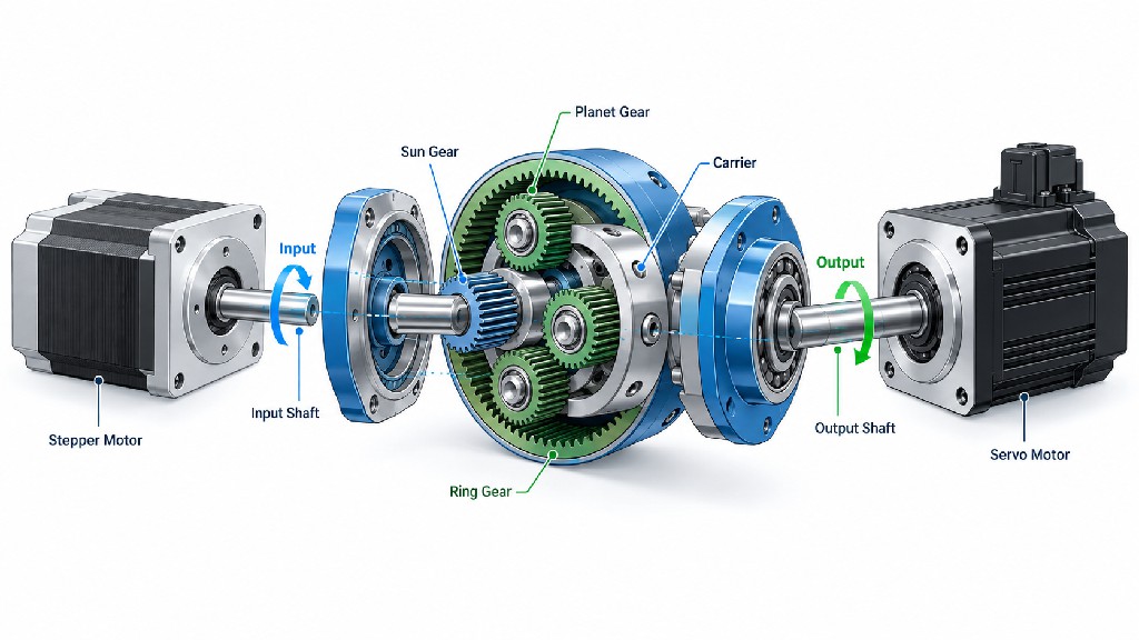
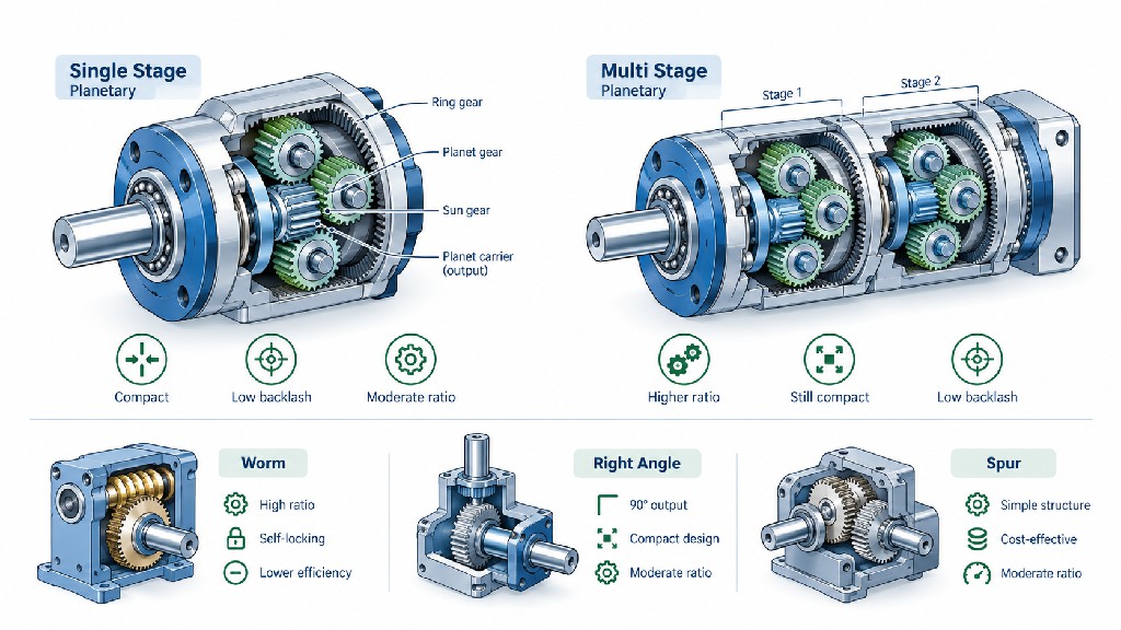
A planetary gearbox—also called a planetary gear reducer, planetary gearhead or epicyclic reducer—transmits mechanical power through multiple gears arranged around a central axis. In a common inline reduction design, the motor shaft drives the sun gear. Several planet gears mesh simultaneously with the sun gear and an internally toothed ring gear. The planets rotate on a planet carrier, which forms the gearbox output. The ring is fixed to the housing for this common configuration.
When the sun rotates, the planet gears both spin around their own axes and orbit the sun. Their orbit makes the carrier turn more slowly than the input, while the output torque increases after mechanical losses are considered. Because several planet gears share tooth contact, a well-designed planetary unit can achieve relatively high torque density in a compact, coaxial envelope.
This architecture brings several practical advantages. Input and output usually share a centerline, making the reducer easy to integrate with a stepper or servo motor. The compact ring-and-planet arrangement offers a favorable torque-to-size relationship. Multiple gears share the load instead of relying on just one external gear pair. Precision versions can use tightly controlled tooth geometry, bearings, housings and preloaded elements to reduce backlash and improve stiffness.
However, the phrase “planetary gearbox” does not guarantee precision. Two reducers with the same 10:1 ratio can differ dramatically in bearing design, backlash, torsional stiffness, continuous torque, operating temperature, lubricant, noise and expected life. describes why gearhead design is as important for positioning and vibration as it is for torque multiplication.
Understanding the basic gear geometry
For the conventional arrangement with a fixed ring, sun input and carrier output, the reduction ratio is:
i = 1 + (N_ring / N_sun)
Here, i is the positive reduction ratio and N represents gear-tooth count. For example, a 20-tooth sun and an 80-tooth ring produce i = 1 + 80/20 = 5:1. This relationship applies to that specific planetary configuration; different fixed and driven members produce different speed relationships. Real gearbox product ratios should always be taken from the manufacturer's specification, not inferred from photographs.
A gearhead can have a simple shaft output, keyed shaft, D-cut shaft, clamping hub or output flange. Choosing among those formats depends on the next mechanical element: pulley, sprocket, rack-and-pinion drive, coupling, robot joint, ball screw or rotary table. That interface can determine whether the compactness of the planetary design is realized in the completed machine.
Planetary Gearbox Reduction Ratio Calculation: Speed, Torque and Power
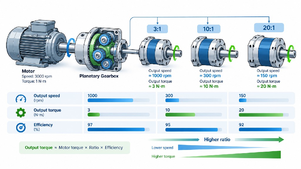
The speed-reduction relationship is straightforward. Define i = input speed / output speed, with both speeds measured in RPM. For an ideal gear ratio, n_out = n_in / i. If the input shaft rotates at 3,000 RPM and the gearbox has a 10:1 ratio, the output rotates at 300 RPM.
Torque increases approximately in proportion to ratio, but only after accounting for mechanical losses. For a simple first-pass planetary gearbox torque calculation, use T_out = T_in × i × η, where η is mechanical efficiency as a decimal between zero and one. This estimate assumes the quoted input torque is actually available at the stated input speed and is within the gearbox's relevant torque and temperature limits.
The useful idealized relationships are summarized below.
| Quantity | Calculation | Unit | Engineering interpretation |
|---|---|---|---|
| Reduction ratio | i = n_in / n_out | Dimensionless | A 10:1 reducer divides motor RPM by ten |
| Output speed | n_out = n_in / i | RPM | Must meet target load speed |
| Predicted output torque | T_out = T_in × i × η | N·m | Not an independent gearbox rating |
| Input mechanical power | P_in = T_in × 2π × n_in / 60 | W | Power from shaft torque and angular speed |
| Output mechanical power | P_out ≈ η × P_in | W | Useful power after gearbox losses |
| Reflected external inertia | J_ref = J_load / i² | kg·m² | Load inertia seen at motor, ignoring added gearbox inertia |
| Motor speed required | n_in = i × n_out | RPM | Check motor torque at this RPM |
Worked example: 0.4 N·m, 3,000 RPM, 10:1, 90% efficiency
Assume a motor produces 0.4 N·m at 3,000 RPM, and a gearbox provides a 10:1 ratio at a 90% assumed efficiency. The theoretical output speed is 3,000 / 10 = 300 RPM. The theoretical transmitted output torque is 0.4 × 10 × 0.90 = 3.6 N·m. This is the reference example used throughout the guide.
A power cross-check makes the arithmetic more transparent. At the input, mechanical power is 0.4 × 2π × 3,000/60 ≈ 125.7 W. At the output, 3.6 × 2π × 300/60 ≈ 113.1 W. The difference—approximately 12.6 W—is the modeled mechanical loss. The values are consistent with 90% efficiency.
Critical engineering limitation: the calculated 3.6 N·m is not automatically an allowable output rating. The gearbox may be rated for only 3 N·m continuous duty; its bearings may be overloaded by a pulley; its lubrication may not support continuous 3,000-RPM input; or shock loads may exceed the permitted short-duration torque. Always compare the calculated output against the actual gearbox's rated torque, peak torque, permissible input speed and thermal limitations, using manufacturer-specific definitions.
Example ratio table: identical input conditions, changing reduction
The following table is purely mathematical. It uses the same 0.4 N·m at 3,000 RPM motor operating point with 90% assumed gearbox efficiency for every ratio. Actual efficiency normally changes with the reducer family, ratio, load, speed and number of stages. Do not use these values as a performance specification for any product.
| Assumed ratio | Calculated output speed | Calculated transmitted torque | Calculated output power |
|---|---|---|---|
| 3:1 | 1,000 RPM | 1.08 N·m | 113.1 W |
| 5:1 | 600 RPM | 1.80 N·m | 113.1 W |
| 10:1 | 300 RPM | 3.60 N·m | 113.1 W |
| 20:1 | 150 RPM | 7.20 N·m | 113.1 W |
| 50:1 | 60 RPM | 18.00 N·m | 113.1 W |
This table shows the fundamental trade-off: lower output speed and higher calculated torque, not creation of extra power. It also exposes why selecting the highest ratio is often a mistake. At 50:1, the load is much slower; high input RPM may be needed to reach the desired cycle speed; and a compact gearbox may not be rated for the 18 N·m calculated from the formula.
For more informed motor selection, read the . It explains why the actual stepper torque–speed curve, not the holding-torque number alone, controls achievable acceleration and sustained performance.
One-Stage vs Two-Stage vs Multi-Stage Planetary Gearboxes
A planetary stage is one functional reduction gearset. Multiple stages are connected in series when the application needs more overall reduction than one stage can conveniently provide. The total ratio is the product of individual stage ratios: i_total = i_1 × i_2 × .... Two stages of 5:1, for example, produce 25:1 total reduction. When estimating drivetrain efficiency, multiply stage efficiencies: ηtotal ≈ η1 × η_2, provided the efficiencies correspond to the relevant operating conditions.
One-stage gearboxes often have a shorter body, fewer tooth meshes and comparatively low mechanical loss. Two-stage products offer greater reduction at the expense of additional length, gear contact, lubrication requirements and accumulated compliance. Three-stage or higher products provide still more reduction, but may be slower and require closer checks of output rating, thermal behavior and reversal accuracy. The exact ratio breakpoints depend on manufacturer geometry.
| Configuration | Illustrative ratio options | Main advantage | Main caution |
|---|---|---|---|
| Single-stage | 3:1, 4:1, 5:1, 7:1, 10:1 | Compact, often efficient | Limited maximum reduction |
| Two-stage | 12:1, 20:1, 25:1, 50:1, 100:1 | Broader speed and torque matching | Additional loss, length and potentially backlash |
| Three-stage or more | Higher ratios, manufacturer-specific | Very low output RPM in one assembly | More heat, compliance and possible size penalty |
These are illustrative ranges rather than universal standard ratios. As a manufacturer reference, list one-stage ratios of 3, 4, 5, 7, 8 and 10, plus two-stage options reaching 100. The same product information illustrates that input-speed, continuous-torque and cyclic-torque ratings are separate engineering constraints.
A useful first decision is to target the smallest ratio that supplies adequate continuous and acceleration torque while keeping the motor inside its effective speed range. For frequent position reversals, compare backlash and stiffness of specific models at the ratio required. Do not assume that all two-stage units have the same backlash or efficiency, because improved gear geometry and manufacturing can make a premium two-stage unit outperform a less accurate one-stage alternative.
Economy Gearbox vs Precision Gearbox: What Are You Paying For?
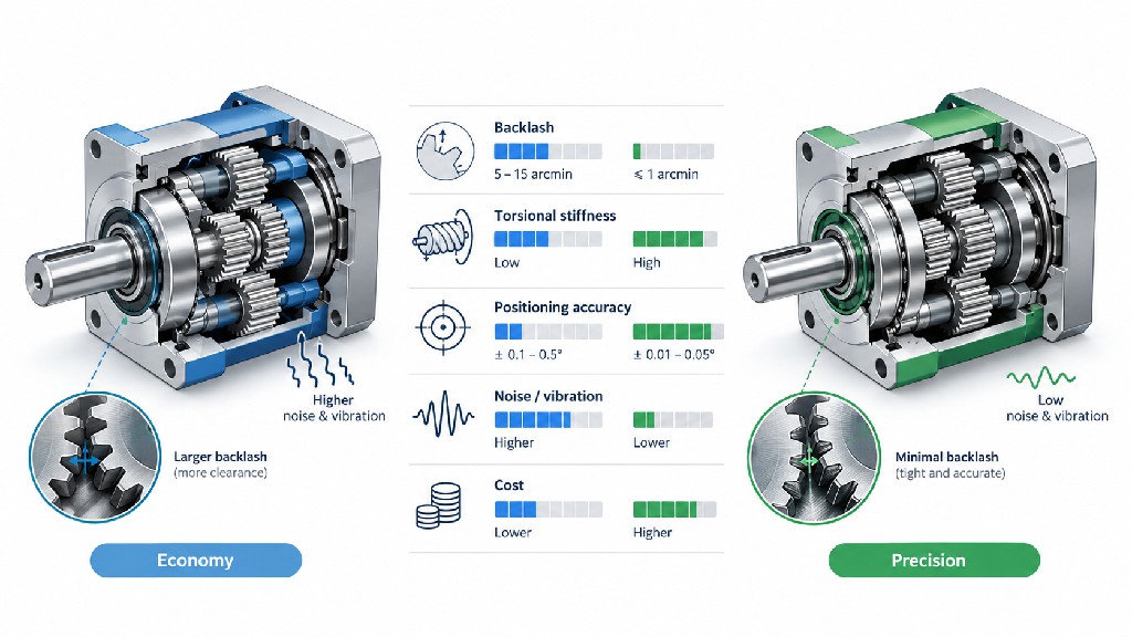
Economy and precision are commercial product classes, not a single worldwide measurement standard. An economy gearbox may be entirely appropriate for a low-cost feeder, conveyor, dispensing station or slowly rotating fixture. A precision gearbox is more attractive when small reversal errors, high dynamic stiffness, repeated indexing accuracy, low vibration and stable backlash over service life are commercially important.
The distinction should be evaluated through measurable specifications rather than adjectives on a listing. Ask for defined backlash, torsional stiffness, motor-adapter runout, bearing capacity, output-interface accuracy, efficiency, noise, lubrication, rated lifetime and duty assumptions. Different manufacturers may test these quantities differently; identical labels do not guarantee comparable measurement conditions.
| Criterion | Economy planetary gearbox | Precision planetary gearbox |
|---|---|---|
| Primary buying priority | Cost, compactness and basic reduction | Reversal accuracy, rigidity and controlled motion |
| Backlash | Often higher; product-specific | Typically lower; product-specific |
| Stiffness | May be adequate for steady loads | Often engineered for lower elastic deflection |
| Bearings and output support | May favor cost and compactness | May offer greater radial, axial or tilting capacity |
| Manufacturing and assembly | Commercial tolerances | More tightly controlled geometry and assembly |
| Good applications | Conveyors, valves, basic feeding and noncritical motion | CNC indexing, robotics, inspection and rapid reversal |
| What to verify | Rated torque, service duty, backlash and life | Same checks plus stiffness and measurement conditions |
Published manufacturer ranges show why fixed rules such as “economy always means 30 arcminutes” are misleading. Neugart's includes standard backlash figures that vary by frame size, while its includes selected configurations with less than one arcminute of backlash. Those are Neugart model specifications, not blanket claims about FRANK HU MOTOR products.
For a practical commercial comparison, contrast a with the company's . Their application requirements and documented numbers are more informative than product-category names alone.
Backlash versus repeatability: the commercial decision
If a conveyor always turns in one direction, higher backlash might not significantly affect final product quality. If a rotary CNC fixture repeatedly reverses to a location, backlash can create dead travel at the output. Software compensation may help in a predictable mechanism, but mechanical wear, changing load direction and elastic deflection can make compensation imperfect. For a medical analysis stage or inspection fixture, the cost of poor repeatability may be far greater than the purchase-price difference between reducers.
Precision also carries an integration cost. A gearbox with exceptionally low backlash cannot guarantee accurate motion if the mount flexes, the output shaft is bent, the motor loses steps or the tool load is connected through a compliant coupling. The best purchasing decision targets the weakest error source in the complete axis, not simply the lowest backlash number in a catalog.
Backlash, Torsional Stiffness and Positioning Accuracy
Backlash is the small amount of relative movement between gear teeth and other transmission elements before torque is fully transmitted in the opposite direction. Manufacturers commonly specify gearbox torsional backlash in arcminutes (arcmin), where 1 arcmin = 1/60 degree. In some economy product listings, backlash is instead expressed in whole degrees. Always convert the unit before comparing two products.
A reducer rated at 10 arcmin has a nominal angular backlash of 10/60 = 0.1667 degree under the applicable test definition. At a point 50 mm from the axis, that angle corresponds to approximate tangential travel of 0.05 m × (10 × π / 10,800) ≈ 0.000145 m, or 0.145 mm. At a 150 mm radius, it corresponds to about 0.436 mm. This is why a tiny-looking angular figure may matter to a long robotic arm or large indexing table.
| Gearbox backlash | Equivalent angle | Approx. lost motion at 50 mm radius | Approx. lost motion at 150 mm radius |
|---|---|---|---|
| 1 arcmin | 0.0167° | 0.0145 mm | 0.0436 mm |
| 5 arcmin | 0.0833° | 0.0727 mm | 0.2182 mm |
| 10 arcmin | 0.1667° | 0.1454 mm | 0.4363 mm |
| 15 arcmin | 0.2500° | 0.2182 mm | 0.6545 mm |
| 2 degrees | 2.0000° | 1.7453 mm | 5.2360 mm |
Calculated geometry: travel = radius × backlash angle in radians. This describes angular clearance mapped to a radius, not guaranteed total machine error. It does not include stiffness, bearing deflection, drive error, tooth profile, mounting or structural flex. Actual measured lost motion depends on test torque and conditions.
Torsional stiffness describes resistance to elastic twisting once the tooth flanks are loaded. It is commonly expressed as N·m/arcmin or N·m/rad. An approximate elastic twist can be found using θ_elastic ≈ T / K_t, with units kept consistent. For example, 6 N·m applied to a gearbox with a hypothetical output torsional stiffness of 3 N·m/arcmin produces approximately 2 arcmin of elastic twist. This deflection is separate from backlash.
Backlash and stiffness solve different problems. Backlash tends to produce a clearance region when changing torque direction; low stiffness can produce changing elastic deflection even if the gears have essentially no clearance. An axis can have excellent reversal backlash but poor contour accuracy under rapidly changing forces. A system can also be stiff under a steady one-way load yet exhibit measurable reversing error.
High-end manufacturer terminology distinguishes positioning accuracy, repeatability, backlash and torsional rigidity. The supplies examples of torsional stiffness alongside backlash. It is the combination—not either number alone—that determines how the transmission responds to load reversals.
Encoder location matters
An encoder fitted only on the motor generally measures the motion before the gearbox. A motor-side servo can tightly control motor rotation while still allowing output backlash and compliance to influence the machine position. An output-side encoder or linear scale can measure actual load motion and may improve closed-loop compensation, provided the controller, sensor resolution, control-loop design and mechanism are suitable. An encoder does not eliminate mechanical backlash, and careless compensation can excite oscillations.
For stepper motors, microstepping increases command resolution and can smooth operation, but it does not guarantee the same improvement in loaded absolute position accuracy. A 1.8° stepper with a 10:1 gearbox has a nominal 0.18° full-step output increment. The actual reachable load position can still deviate because of detent torque, load, motor current, microstep nonlinearity, backlash, elastic twist and missed steps.
When requesting a low backlash planetary gearbox, ask for the measurement definition: is backlash recorded at no load or under a specified test torque, with the input locked, and at what temperature? Compare like-for-like data whenever possible. Backlash can also change with life and wear, especially in mechanisms that reverse frequently.
Rated Torque, Peak Torque, Emergency Torque and Service Factor
A planetary reducer may have several torque figures, each describing a different operating condition. Rated output torque often refers to a continuous or cyclic duty requirement, but the exact definition differs among manufacturers. Maximum or peak output torque may be permitted only for short periods, a limited number of cycles, or a specific duty profile. Emergency-stop torque can represent a rare exceptional load rather than a usable operational peak.
For a reliable purchase specification, ask whether the catalog rating is continuous, average, cyclic, acceleration-related or short-duration. Ask what input speed, lubricant temperature, duty cycle and life calculation underpin the rating. A gearbox operated at a high speed or high ambient temperature may have a lower sustainable torque than the same gearbox at a moderate speed with adequate heat dissipation.
| Torque category | Typical engineering use | Mistake to avoid |
|---|---|---|
| Continuous output torque | Long-duration operation at operating speed | Substituting a motor holding-torque figure |
| Nominal/cyclic output torque | Repetitive start–stop or reversing duty, per manufacturer's definition | Treating a cyclic rating as universal continuous duty |
| Acceleration or peak torque | Short acceleration or transient events | Applying it throughout a long duty cycle |
| Emergency-stop torque | Uncommon abnormal stopping events | Using it as a production peak rating |
| Static holding torque | Holding a stopped axis, if gearbox and brake permit | Assuming static holding proves safe moving operation |
The manufacturer's own language matters. As one illustration, separately identify cyclic, maximum, continuous and emergency-stop output torques. This demonstrates why selection cannot be reduced to whichever torque figure is largest.
Applying a service factor without double-counting
A service factor allows for uncertain shock, workload variation or operating severity. A simplified early-stage check is T_design = K_s × T_required, where K_s is an agreed service factor. If an application needs 8 N·m output under expected operation and the design team adopts K_s = 1.5, a first-pass target becomes 12 N·m. The number 1.5 is only an illustrative engineering assumption, not a universal planetary-gearbox recommendation.
Whether to apply a separate factor depends on how the manufacturer defines its ratings and selection method. Some methods already incorporate fatigue, load-cycle spectrum and shock classifications. Adding arbitrary margins to every input can oversize the gearbox and motor, increase rotor inertia and raise the system price without improving actual reliability. Conversely, a steady-torque calculation can overlook severe shock at startup, emergency stop, backlash take-up or tool collision.
For strongly reversing or impact-driven axes, give the supplier a time-based torque profile. The gearbox may require an equivalent fatigue torque based on a manufacturer-prescribed exponent and load histogram; it is unsafe to invent a generic formula for all gearbox tooth geometries. At minimum, distinguish run, acceleration, deceleration, holding and fault events.
Radial Loads, Axial Loads and Overhung Moments
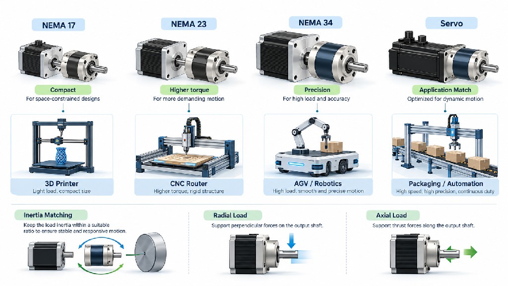
A gearbox output shaft does more than transmit torque. Belts, pulleys, sprockets, pinions and heavy attached equipment place radial forces on the shaft and output bearings. Helical gears, leadscrews and certain thrust mechanisms can impose axial forces. Loads applied at an offset from the bearing generate bending or tilting moments that may reduce bearing life even when the transmitted torque is moderate.
Imagine a pinion mounted 60 mm beyond the gearbox bearing support. If it experiences a 300 N transverse force, its approximate bending moment about that reference is 300 × 0.060 = 18 N·m. Moving the pinion farther outward increases the moment even though motor torque is unchanged. This is why output-shaft diameter alone cannot establish permissible side load.
| External element | Load to investigate | Typical integration response |
|---|---|---|
| Belt pulley | Belt tension and shaft overhang | Reduce cantilever distance or use external support |
| Chain sprocket | Chain pull, shock and tension | Check bearing load and alignment |
| Rack-and-pinion | Tangential tooth force and separating force | Check radial load, pinion support and backlash |
| Helical gear pair | Radial and axial components | Check thrust capacity and bearing arrangement |
| Robot arm joint | Tilting moment, changing gravity and impact | Consider flanged or externally supported output |
| Direct coupling to supported shaft | Alignment and coupling reaction loads | Favor proper support and flexible coupling |
Permissible radial and axial force figures are often specified at a particular position on the shaft, under defined speed and lifetime assumptions. If the actual load is farther from the bearing, a simple comparison against catalog force may be misleading. Use the manufacturer's load calculation or ask for approval of the specific geometry.
As a real reference, lists separate radial, axial and maximum tilting-moment ratings. These are not interchangeable numbers. A mechanism can pass its torque calculation and still fail an output-bearing check. When radial or axial loads are large, supporting the driven load with external bearings often produces a more robust and economical design than buying an oversized reducer solely for its output bearing.
Load Inertia Matching and Acceleration Torque
A gearbox changes the inertia a motor sees. This matters enormously in high-speed pick-and-place systems, rotary tables, gantries and AGV drives. Under an ideal rigid reduction, the load inertia reflected to the motor is J_reflected = J_load / i². A 10:1 ratio reduces the reflected external inertia by a factor of 100. This can let a relatively small motor accelerate a load that would otherwise be poorly matched to its rotor inertia.
But an inertia calculation must include the gearbox's own input-referred inertia, motor rotor inertia and any intermediate couplings. A high reduction ratio also requires the motor to turn proportionally faster to achieve the same load speed. The proper ratio therefore balances inertia matching against motor torque availability at the increased RPM, heat, duty and cost.
Acceleration torque at the output can be approximated by T_acc,out = J_total,out × α_out, where α_out is output angular acceleration in rad/s², provided the inertia is expressed at the output. Add load torque from gravity, friction, process force and other mechanisms. At the motor, the ideal acceleration contribution of reflected external load is J_load × α_out / (i × η) under the forward-driving approximation, or equivalently (J_load / i²) × α_in / η, where αin = i × αout. Different dynamic models account for gearbox losses and inertia more precisely.
Numerical inertia and acceleration example
Suppose a rotating load has inertia J_load = 0.020 kg·m² and must accelerate at 30 rad/s². Its inertial torque at the output is 0.020 × 30 = 0.60 N·m, before friction, process load and shock. At 10:1, the motor sees the external inertia as 0.020 / 100 = 0.00020 kg·m², while its angular acceleration is 300 rad/s². Ignoring loss, the required motor acceleration torque for that load is 0.00020 × 300 = 0.060 N·m; allowing an assumed 90% forward efficiency makes the approximate required torque 0.067 N·m, before adding motor and gearbox inertial acceleration.
Now imagine the machine must accelerate ten times faster: output acceleration rises to 300 rad/s² and inertial output torque becomes 6 N·m. The same gearbox and motor that appear adequate under slow movement can become unsuitable under fast indexing. This is why a sales quotation based only on “required holding torque” is incomplete.
The detailed expands the reflected-inertia method. A manufacturer-grade tool such as the can evaluate complete drive combinations against actual application profiles. Such tools are especially useful when a cycle includes rapid reversals, regenerative braking and significant variable external loads.
Don't chase a single universal inertia ratio
You may encounter informal design rules claiming that reflected load inertia should always be less than five or ten times motor inertia. Those can be useful starting points in some control contexts, but they are not universal acceptance limits. A properly tuned servo may tolerate a much higher ratio in a favorable mechanical system. A stepper may be unstable at a smaller ratio if the motion profile crosses resonance or the available dynamic torque is inadequate. Treat inertia ratio as one input to the dynamic model, not a pass/fail number independent of control bandwidth, stiffness and duty cycle.
Selecting a Planetary Gearbox for NEMA 17, NEMA 23 and NEMA 34 Stepper Motors
The NEMA number is primarily a mounting-frame designation. It does not uniquely determine motor torque, current, rotor inertia, shaft diameter, thermal capability or torque at speed. Two NEMA 23 motors may have very different performance curves. Likewise, a NEMA 34 holding-torque value does not establish how much power the motor can deliver at 600 RPM or whether a chosen planetary reducer can survive the calculated output torque.
| Stepper frame | Typical frame face | Common geared-motion role | Selection focus |
|---|---|---|---|
| NEMA 17 | About 42 × 42 mm | Compact robotics, dispensing, small rotary fixtures | Space, motor heat, torque at speed, gearbox output limit |
| NEMA 23 | About 57 × 57 mm | CNC indexing, moderate conveyors, packaging equipment | Acceleration, gear ratio, precision, shaft loads |
| NEMA 34 | About 86 × 86 mm | Heavier rotary axes, industrial drives, larger mechanisms | Gearbox torque ceiling, input RPM, inertia and bearing forces |
Frame dimensions are nominal family values; always confirm drawings and adapter interfaces. The explains why frame size and torque should never be treated as synonyms.
NEMA 17 planetary gearbox: small space, limited output rating
NEMA 17 is attractive in compact equipment because its mounting footprint is modest. Typical buyers want slower, quieter motion, higher available output torque or better load inertia matching. Before choosing a deep reduction, confirm whether the moving axis needs fast travel. A 50:1 gearbox might work for slow rotation but be an obstacle to rapid repositioning.
Consider FRANK HU MOTOR's . Its catalog lists a 51:1 economy planetary gearbox, 70% stated efficiency, up to 2° no-load backlash, 4.0 N·m rated gearbox torque and 6.0 N·m maximum gearbox torque. The motor has 0.45 N·m holding torque, but multiplying 0.45 × 51 × 0.70 gives roughly 16.1 N·m, well above the gearbox's 4.0 N·m rated value. More importantly, holding torque is not the motor's usable running torque. The simple multiplication must not be used as the actual continuous output rating.
The practical conclusion: for a slow, low-cost positioning mechanism, the economy assembly may be an excellent choice if the torque, backlash and duty requirements fit its ratings. For a reversal-sensitive metrology axis, its 2° specified no-load backlash may be unacceptable even if the torque capacity is sufficient.
NEMA 23 planetary gearbox: versatile industrial integration
NEMA 23 is frequently a useful middle ground between cost, package size and operating capability. It is suitable for small CNC accessories, light robotic arms, indexing tables, rotary labelers, dosing machinery and guided conveyors. Engineers should first plot the required speed and torque profile. Some applications need a relatively low reduction ratio for fast travel; others prioritize torque and stability at modest output speed.
A specific example is . The published data show 10:1 reduction, 96% efficiency, no-load backlash of up to 15 arcmin and 25 N·m rated gearbox torque, paired with a motor listed at 1.2 N·m holding torque. The nominal holding-torque multiplication works out to about 11.5 N·m, but this is not a running-torque guarantee. Its real moving torque depends on supply voltage, current, driver, acceleration and operating RPM.
Another NEMA 23 gearbox, , also has 10:1 reduction and 96% listed efficiency, yet its gearbox rated torque is 10 N·m, with 15 arcmin no-load backlash. The motor is listed at 1.9 N·m holding torque. Calculating 1.9 × 10 × 0.96 ≈ 18.2 N·m would exceed the gearbox's published 10 N·m rating even before deciding what the motor can produce dynamically. This is a textbook reason to read the individual model specification rather than assume that “NEMA 23, 10:1” describes one standardized transmission.
NEMA 34 gearbox: verify gearbox limits before increasing motor size
A NEMA 34 geared assembly is often considered for heavier industrial axes. It can provide substantial low-speed torque, but more motor holding torque can create an expensive illusion of safety if the gearbox output rating is lower. A larger motor also adds mass and can increase the drive's electrical and mechanical requirements.
FRANK HU MOTOR's lists 10:1 reduction, 96% efficiency, 10 arcmin no-load backlash, a 39 N·m gearbox rated torque and 8.5 N·m motor holding torque. If someone multiplies the holding torque by ratio and efficiency, the result is about 81.6 N·m—more than twice the listed gearbox rating. The assembly must be engineered around the actual speed-dependent motor torque and the 39 N·m gearbox rating, not the larger arithmetic value.
For NEMA 34 work, be especially careful about output-pin forces, large pulley loads and machine vibration. A separate externally supported shaft, careful coupling selection or different output-flange gearbox may be required even when the gearbox torque appears sufficient.
Servo Motor Planetary Gearbox Selection
A servo motor planetary gearbox is often selected to raise output torque, reduce reflected load inertia and maintain controlled motion during frequent starts, stops and reversals. Compared with a basic open-loop stepper, a servo drive typically provides speed and torque feedback, overload management and more sophisticated motion control. However, the gearbox still has mechanical clearance, stiffness, bearing and heat limits. Adding a servo does not make an unsuitable gearbox appropriate.
Begin by obtaining the servo's continuous torque–speed envelope, peak torque capability, maximum speed, rated speed, rotor inertia, encoder specification, braking behavior and thermal duty. Determine the output move profile and translate its speed demand through each candidate reduction ratio. A 3,000-RPM rated servo with a 5:1 reducer produces a theoretical 600-RPM rated output speed, while a 10:1 unit yields 300 RPM. If the machine requires 450 RPM at the output, a 10:1 ratio would demand 4,500 RPM at the motor. That may be possible for a particular servo, but only if its allowable speed and torque at that speed are verified.
For a numerical illustration, a 750 W motor delivering its rated power at 3,000 RPM has nominal shaft torque of approximately 750 ÷ (2π × 3,000/60) = 2.39 N·m. With 5:1 reduction and an assumed 95% efficiency, predicted output torque is 2.39 × 5 × 0.95 ≈ 11.35 N·m at 600 RPM. With 10:1 and the same assumed efficiency, it is approximately 22.7 N·m at 300 RPM. These examples describe an operating point, not a recommendation for a particular 750 W servo or gearbox model.
The gearbox's maximum permitted input speed is especially important for servos. Some gearboxes have a continuous input-speed limit and a higher maximum mechanical input speed. A short acceleration peak near the latter is not equivalent to operating there all day. Also check the servo's maximum torque during an emergency stop or deceleration; high peak motor capability can damage an undersized gearbox if the drive does not enforce appropriate limits.
When precision servo reduction pays for itself
Precision reduction often makes economic sense when it prevents machine-level problems: contour error in CNC work, overshoot on a packaging pick-and-place axis, vibration in a camera positioning mechanism, or rework caused by inconsistent indexing. The correct metric is not gearbox price alone. It is the total cost of qualifying the axis, achieving cycle time, maintaining product quality and avoiding unexpected downtime.
For demanding machines, request the gearbox's torsional stiffness, no-load or load-dependent backlash, input inertia, maximum radial and axial loads, output interface drawing and life assumptions. A servo with an output-side encoder may benefit from better feedback, but stiffness and mechanical dynamics must still permit a stable controller. If the load includes gravity or a vertical axis, evaluate holding-brake requirements and fail-safe design separately; do not assume a planetary gearhead is self-locking.
As one practical product-family example, FRANK HU MOTOR lists 42 mm, 24 V, 60 W geared brushless DC servo motors with planetary options including 10:1 at a listed 300 RPM / 2.0 N·m. These catalog figures describe particular integrated products—not generic torque guarantees for every 60 W servo. Browse the together with to discuss motor flange and shaft compatibility as a matched combination.
Planetary vs Worm, Right-Angle and Spur Gearboxes
Planetary gearing is a strong default when the buyer needs inline geometry, compactness, balanced torque capacity and useful positioning behavior. But it is not always the lowest-cost or most compact solution for the overall machine. Shaft orientation, required ratio, reversibility, available space, noise, lubrication, efficiency and safety requirements can make a different architecture preferable.
| Gearbox design | Shaft arrangement | Key strengths | Common limitations | Typical application |
|---|---|---|---|---|
| Planetary | Usually coaxial | High torque density; compact; low-backlash options | Precision versions can cost more | CNC rotary axes, automation, servos |
| Worm gear | Usually approximately 90° | High ratios in compact right-angle package; smooth output | Sliding losses and heat; possible high backlash; self-locking not guaranteed | Valves, slow conveyors, simple lifts with independent safety |
| Right-angle bevel/hypoid | 90° or offset axes | Redirects motion while offering efficient compact layouts | Design- and model-dependent accuracy; can be more complex | Space-constrained conveyors and automation |
| Parallel-shaft spur gear | Parallel, offset axes | Economical, familiar construction; easy to service in some designs | More space for a given layout; tooth noise and backlash depend on design | Simple machinery and cost-sensitive drives |
Right-angle describes shaft geometry rather than a single gear-tooth mechanism. A right-angle reducer may use bevel gears, hypoid gears or a planetary stage combined with a right-angle input. Similarly, spur refers to gear-tooth geometry and can appear in multiple gearbox architectures, including some planetary reducers. These terms should not be treated as perfectly exclusive categories.
Worm gearing deserves special caution. Some worm gear sets resist back-driving under certain friction and geometry conditions, but that resistance can vary with lubrication, wear, temperature, vibration and load. A worm gearbox must not be used as a substitute for a certified holding brake in a safety-critical vertical axis unless the complete machine's safety engineering explicitly allows it.
For alternatives available through the same supplier, see and the , which also lists worm and right-angle product families. Selecting the right transmission type before finalizing the motor can eliminate unnecessary adapters or redesigns.
Published FRANK HU MOTOR Gearbox Specifications: An Engineering Comparison
Actual product specifications are more useful than generalized claims about gearbox families. The table below brings together selected catalog values from individual FRANK HU MOTOR pages. All values are published product data, not independent third-party test measurements; verify the latest drawings, actual duty rating and available configuration with the supplier before ordering. The motor's holding torque, where available, must not be interpreted as dynamic motor torque at operating speed.
| Example model and type | Ratio | Listed efficiency | Listed no-load backlash | Listed gearbox rated output torque |
|---|---|---|---|---|
| 4:1 | 96% | ≤15 arcmin | 4.0 N·m | |
| 51:1 | 70% | ≤2° (120 arcmin) | 4.0 N·m | |
| 10:1 | 96% | ≤15 arcmin | 25 N·m | |
| 10:1 | 96% | ≤15 arcmin | 10 N·m | |
| 10:1 | 96% | 10 arcmin | 39 N·m |
The table reveals three selection lessons. First, a high ratio is not proof of high continuous output torque. Second, a 10:1 label is not enough to identify the appropriate gearbox capacity: two NEMA 23 assemblies at the same ratio can carry published ratings of 10 N·m and 25 N·m. Third, backlash units matter: 2° equals 120 arcmin, a substantial difference from a model specifying 10 or 15 arcmin.
Catalog verification note: on the EGS8-G4 page, one descriptive sentence refers to a 5:1 ratio, while the SKU/title and structured specifications refer to 4:1. The comparison table follows the structured 4:1 specification. Confirm the current engineering drawing before using that model in a final design. For all models, confirm how the seller defines “rated” and “maximum” torque and whether the quoted backlash is measured at no load.
A buyer comparing packages can also use these specifications to ask better questions: Is the maximum torque permitted during acceleration? What test torque defines backlash? How does efficiency vary at low load? Does the unit require a special shaft length or adapter? The first quotation should resolve those ambiguities before the mechanical design is frozen.
Four Application Examples: From Compact Steppers to Dynamic Servos
Example A: Laboratory sample tray with NEMA 17
A lab sample tray requires low speed, modest continuous torque and occasional position changes. The output must rotate at about 12 RPM, and the motor has a confirmed usable operating point near 600 RPM. An initial ratio estimate is 600/12 = 50:1. The ratio is plausible, but it is only a starting point. The engineer must measure actual acceleration torque, sample-tray inertia and starting friction, and determine whether backlash affects sampling alignment.
If motion is always approached from the same direction and backlash tolerance is generous, a low-cost economy gearhead may be justified. If the tray frequently reverses and samples need precise angular alignment, the apparent savings may disappear in calibration or rework. The project might use a lower-backlash gearbox, output reference sensor or different motion approach. The assembly should still be checked against the gearbox's rated output torque and radial load, even if the motor appears small.
Example B: CNC rotary indexer with NEMA 23
A small CNC fixture requires 60 RPM output under moderate cutting disturbance, with frequent reversals. Suppose the selected stepper has useful dynamic torque at 600 RPM; a 10:1 ratio is the obvious speed starting point. The designer should calculate normal operating torque, acceleration torque from the fixture inertia and any cutting moment reflected to the rotation axis, then compare those values with specific gearbox ratings. In this application, nominal step count alone cannot establish accuracy, because a reversal may take up backlash before the fixture moves.
Comparing shows why the mechanical drawing, rated gearbox torque and desired backlash should determine the quote. If the fixture's indexing tolerance is very tight, a lower-backlash reducer and a load-side position sensor may be justified. The final choice must also check output bearings if the fixture weight is carried directly by the gearbox shaft.
Example C: Industrial rack-and-pinion drive with NEMA 34
Consider a rack-and-pinion system whose pinion pitch radius is 25 mm and whose required tangential driving force is 500 N, ignoring friction and acceleration for the moment. Output torque is T = F × r = 500 × 0.025 = 12.5 N·m. If acceleration and process forces increase the necessary output torque to a design maximum of 25 N·m, a gearbox may need sufficient cyclic and peak margin above that demand. The pinion also applies substantial force to the output bearings, so the bearing load and pinion overhang may become as important as the torque.
A NEMA 34 motor does not automatically solve these issues. Verify the stepper's dynamic torque at the required motor RPM, the gearbox's published output rating, the pinion shaft support and the complete duty cycle. If the pinion is placed far from the gearbox bearing, an externally supported shaft may be more economical than a larger motor and reducer.
Example D: Fast servo-driven packaging axis
A servo indexing station needs rapid reversals rather than maximum static holding force. Its output speed target is 300 RPM and its motor operates effectively at 3,000 RPM, pointing toward 10:1 reduction. The correct gearbox must support acceleration peaks, braking torque and many repeated load reversals. Stiffness may become critical because a compliant system can oscillate even when average torque is below the rating.
For this application, compare at least two ratios and check servo control tuning, output backlash, gear-mesh dynamics, reflected inertia and thermal duty. A precision planetary gearbox may lower the cost of missed cycles and reduce maintenance intervention. But there is no general reason to pay for sub-arcminute backlash if the total machine tolerance and control objectives do not require it.
Planetary Gearbox Ratio & Output Torque Calculator
Use the Planetary Gearbox Ratio & Output Torque Calculator to screen a possible combination. Enter motor speed, motor torque at that speed, gearbox ratio and assumed efficiency. The outputs are predicted gearbox output speed, transmitted output torque and power. When available, enter the candidate gearbox’s rated torque too: the calculator can then highlight a preliminary rating conflict. This screening tool does not replace a manufacturer’s application review.
| Input | Default worked-example value | What the value must represent |
|---|---|---|
| Motor speed | 3,000 RPM | Actual motor shaft speed at the chosen operating point |
| Motor torque | 0.4 N·m | Available torque at that speed, not automatically stepper holding torque |
| Gearbox ratio | 10:1 | Positive input-to-output reduction |
| Mechanical efficiency | 90% | Assumed efficiency for this ratio, load and speed |
| Calculated output speed | 300 RPM | 3,000 ÷ 10 |
| Calculated output torque | 3.6 N·m | 0.4 × 10 × 0.90 |
| Calculated output power | 113.1 W | Approximately 90% of input shaft power |
Calculator warning: this is a preliminary transmission calculation, not a gearbox safety certification. Do not treat its output as a continuous torque rating. Verify manufacturer-rated torque, peak and shock limits, input speed, overhung loading, heat, lubrication and lifespan. Motor torque must come from the real operating curve, drive setup and thermal conditions.
<!-- INTERACTIVE CALCULATOR EMBED POSITION: Insert the companion planetary-gearbox-calculator.html via a trusted CMS custom-HTML module or developer template. Preserve the static worked-example table above as a no-script fallback. -->
Engineering Purchasing Checklist and Request for Quotation
A productive gearbox purchase starts with an RFQ that gives the supplier enough information to verify the assembly. Instead of asking only for “a 10:1 NEMA 23 gearbox,” send an application brief. The more complete the specification, the more likely the supplier can quote a tested, compatible drivetrain rather than a motor and gearbox chosen independently.
-
Load and motion: target output RPM, continuous torque, peak torque, rotational inertia, acceleration, deceleration, direction changes and total duty hours.
-
Precision: acceptable output backlash, repeatability, static stiffness, stopping error, and whether output feedback is used.
-
External loads: shaft-mounted pulley/pinion details, radial and axial forces, shaft overhang and external support bearings.
-
Motor and control: stepper or servo type, torque–speed curve, rated and maximum RPM, drive voltage/current, encoder and brake requirements.
-
Mechanical integration: flange drawing, shaft diameter and length, pilot, keyway, coupling, orientation, package envelope and CAD/STEP file.
-
Environment and lifecycle: ambient temperature, moisture, contamination, duty cycle, lubrication, lifetime target, vibration and service access.
-
Commercial terms: sample qualification, OEM/ODM customization, documentation, acceptance testing, lead time, batch consistency and warranty.
Ask for a quotation covering the complete assembly wherever practical. FRANK HU MOTOR supplies stepper motors, integrated geared steppers, standalone reducers and related motion-control components. A combined purchasing discussion can include the motor winding, gearbox ratio, driver, shaft geometry, cable length, connector, encoder and optional brake, which reduces avoidable interface mismatches.
Reducing total cost of ownership instead of chasing unit price
An economy gearbox may have the lowest invoice cost but require extra alignment, calibration or planned replacement. A precision model may cost more while reducing scrap, maintenance and cycle-time variability. Neither option wins automatically. Evaluate the price of the entire installed drivetrain, not just the bare reducer. Include driver upgrades, adapter machining, couplings, guarding, spare parts and the cost of qualification testing.
For repeat OEM orders, request documented tolerances and a controlled part-number configuration. A motor/gearbox pairing that works in one prototype should still undergo thermal testing, endurance testing and sample-to-sample validation. A purchase order that specifies ratio alone does not protect against changes in backlash, gearbox bearing design or shaft interface.
Common Planetary Gearbox Selection Mistakes
Using motor holding torque as continuous shaft torque. Hybrid stepper holding torque is measured under stopped conditions; usable torque falls with speed according to the motor, driver and supply. Use a torque–speed curve at the intended operating point.
Ignoring the gearbox rated output torque. Gearboxes impose their own mechanical ceiling. A larger motor or higher reduction does not remove that ceiling; it may make overload more likely.
Comparing backlash numbers with different units or test conditions. Arcminutes and degrees are not interchangeable. A no-load figure may not describe lost motion when torque reverses under production load.
Selecting the highest reduction ratio available. More reduction lowers output RPM and can force a stepper into an unfavorable high-speed torque region. It can also increase length, mechanical loss and torsional compliance.
Confusing low backlash with zero total positioning error. Motor accuracy, structural compliance, output bearing deflection, couplings and feedback location may dominate the system error budget.
Ignoring pulley and pinion overhung loads. Gear tooth torque can be within limit while output bearings are overloaded. Ask for permissible radial/axial forces at the actual shaft geometry.
Checking peak torque without thermal duty. A servo's peak torque or a gearhead's maximum torque may be valid only briefly. Validate cycle history, input RPM, losses and allowable ambient temperature.
Treating self-locking as a safety brake. Some worm reducers may resist back-driving, but safe holding of a gravity-loaded axis requires an appropriate risk assessment and independent safety provisions.
Frequently Asked Questions
What reduction ratio should I choose for a planetary gearbox?
Begin with i = motor RPM / target output RPM, then evaluate a few nearby standard ratios. For each candidate, compare the motor's available dynamic torque at the resulting speed with the actual load and acceleration demands. Check gearbox-rated torque and its input-speed limit. There is no universally best ratio: 5:1 may suit a relatively fast indexer, while 20:1 or 50:1 may fit a slower actuator with different torque requirements.
How do I calculate planetary gearbox output torque?
For a preliminary estimate, calculate T_out = T_motor × ratio × efficiency. The motor torque must be available at the chosen operating speed, and efficiency must be appropriate for the reducer and duty. The result must then be checked against gearbox-rated and peak torque, shaft loads, lubrication and heat limitations. For example, 0.4 N·m at 3,000 RPM through a 10:1 reducer at 90% efficiency produces a calculated 3.6 N·m at 300 RPM, not a guaranteed continuous gearbox rating.
Is a low backlash planetary gearbox always better?
Not always. Low backlash matters most when the load repeatedly reverses, follows a precise contour or requires accurate bidirectional positioning. For a one-way feeder or slow conveyor with generous tolerance, a modest-cost economy model may provide better value. Even very low backlash will not correct weak structural stiffness or inadequate motor torque.
How much does a planetary gearbox improve stepper motor accuracy?
Reduction decreases the nominal output step angle. A 1.8° motor with 10:1 reduction has a 0.18° nominal full-step output increment. However, that does not imply 0.18° guaranteed absolute output accuracy. Backlash, elastic twist, driver behavior, loading and missed steps must also be considered. An encoder or output sensor may be appropriate when actual positioning accuracy is critical.
Can I attach any planetary gearbox to a NEMA 23 or NEMA 34 motor?
No. Frame class is only one dimension. Check motor shaft diameter and length, gearbox adapter, locating pilot, flange pattern, permissible input RPM, transmitted torque and mechanical compatibility. The motor must also match the driver and duty cycle. When possible, obtain an engineered motor-and-gearbox assembly rather than matching parts using frame size alone.
What is the difference between rated torque and maximum torque?
Rated torque generally represents a defined continuous or cyclic duty condition; maximum torque is often a short-duration limit. The meanings vary by brand and series. Obtain the manufacturer's exact definitions, allowable event duration, cycle count, input speed and temperature assumptions. Never use the larger maximum figure as a substitute for the continuous or cyclic requirement.
Should a servo motor use a planetary gearbox?
A servo benefits from planetary reduction when it needs greater output torque, improved load inertia matching or compact coaxial transmission. It may not need reduction when direct drive already meets torque, speed and stiffness requirements. For rapid reversal, evaluate torsional stiffness, peak braking torque, backlash and gearbox input inertia alongside the servo's motion-control capability.
Does a planetary gearbox need maintenance?
That depends on the specific product. Many small sealed gearheads are factory lubricated and have limited routine maintenance requirements, but operating temperature, contamination, load, speed and installation affect useful life. Check the applicable manufacturer's maintenance and lubrication instructions, not a generic “maintenance-free” assumption.
Choose a Complete Geared Motor Solution with FRANK HU MOTOR
Good planetary gearbox selection connects mechanical performance with purchasing simplicity. The recommended workflow is: define motion and load → calculate operating speed and torque → choose candidate ratios → check the motor's dynamic capability → verify gearbox torque and bearing ratings → evaluate backlash and stiffness → validate mounting and environment → test a complete assembly under the actual duty cycle.
FRANK HU MOTOR supports applications ranging from compact NEMA 17 geared mechanisms to NEMA 23 and NEMA 34 industrial motion systems, as well as motor and motion-control requirements that call for servo feedback. Buyers can begin with the , compare , and review the before preparing an RFQ.
Need help selecting a gearbox, geared stepper or matched servo transmission?