A motor can produce torque without telling the machine exactly where its shaft is. For a fan, that may be sufficient. For a CNC axis, robot joint, automated dispensing head or precision positioning stage, it often is not. The control system needs feedback to determine speed, rotation direction, angular position, or whether commanded movement actually occurred. That is the job of a motor encoder or another suitable position sensor.
Choosing among motor encoder types is therefore a system-level decision, not simply an accessory purchase. An inexpensive incremental encoder may be the best match for a closed-loop stepper. Three Hall switches may provide all the information a cost-sensitive BLDC drive needs for six-step commutation. A servo that must resume motion after an unexpected power interruption may justify an absolute encoder. And a high-accuracy CNC axis may need a linear scale on the load even when its motor already contains a high-resolution encoder.
This guide explains incremental vs absolute encoder technology, Hall sensor vs encoder selection, single-turn and multi-turn feedback, optical and magnetic sensing, A/B/Z quadrature, encoder PPR vs CPR, and what motor encoder resolution actually means. It also covers electrical interfaces, noise, grounding, motor-driver compatibility and the commercial questions that should be resolved before ordering a complete motion-control system.
The central principle: buy the feedback system that the application and drive can use reliably. The largest resolution number is not automatically the most accurate, fastest, safest or most economical solution.
Quick Answer: Which Motor Encoder Type Should You Choose?
Start with the control task rather than the encoder catalog.
| Application or requirement | Sensible starting point | Reason | Main question to verify |
|---|---|---|---|
| Cost-sensitive BLDC fan or pump | Sensorless control or three digital Hall sensors | Basic commutation and speed control | Does starting torque or near-zero-speed control require sensors? |
| BLDC conveyor requiring low-speed position control | Incremental encoder, magnetic angle sensor or a suitable absolute encoder | More detailed rotor feedback than basic Hall switching | Can the drive use the sensor for commutation and position control? |
| CNC router axis with a closed-loop stepper | Incremental A/B encoder, commonly supplied as a matched motor-and-drive set | Detects motion errors and supports correction within system limits | Does the chosen driver accept the encoder voltage, wiring and count rate? |
| General industrial servo positioning | Compatible absolute or incremental servo feedback | Enables closed-loop speed and position regulation | Is the feedback protocol supported by the servo drive? |
| Robot joint that must know its position at startup | Absolute encoder; multi-turn if revolutions must be distinguished | Provides position without conventional incremental homing | Is shaft position enough, or must joint/load position also be measured? |
| Long-travel axis with belt or ballscrew compliance | Motor feedback plus load-side scale or encoder when justified | Measures errors after the transmission | Does the controller support full-closed-loop or dual-loop feedback? |
| Machine with frequent unplanned power loss | Absolute feedback with verified turn retention strategy | Improves restart position knowledge | Can multi-turn position survive power-off motion? |
| High electrical-noise industrial installation | Differential incremental output or a drive-supported robust serial interface | Better signal integrity than unprotected single-ended wiring | What cable, shielding, termination and grounding are specified? |
These are starting points, not interchangeable prescriptions. A magnetic encoder can be incremental or absolute. An optical encoder can also be incremental or absolute. A Hall-effect sensing element can form part of a sophisticated absolute angle encoder, even though three conventional digital Hall switches normally provide only coarse rotor-sector information. Comparing sensor physics with output format as if they were the same category is one of the most common procurement mistakes.
What Is a Motor Encoder and What Does It Measure?
A motor encoder converts shaft or rotor movement into electrical or digital feedback. Depending on its design, it may report motion pulses, rotation direction, speed, position within one turn, or the number of completed turns. The motor drive or motion controller interprets this information to regulate the motor and monitor the axis.
In a position loop, the controller compares the requested position with measured position. Their difference is the following error or position error. The control algorithm uses that error to produce an appropriate command. A speed loop similarly compares requested and observed rotational speed. For a brushless motor, the controller may also need rotor electrical angle to energize the correct phases.
It is important to distinguish three possible feedback locations:
-
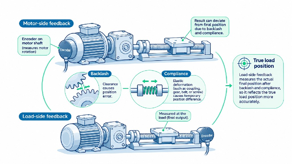
Rotor or motor-shaft feedback observes the motor itself. It is excellent for commutation and motor regulation but cannot directly see backlash downstream.
-
Transmission or output-shaft feedback observes the geared or coupled output. It can reveal some gearbox and coupling effects but may be less suitable for high-bandwidth motor commutation.
-
Linear or load-side feedback observes the actual carriage, tool or machine element. It can expose transmission error, screw pitch variation and thermal growth that the motor encoder does not measure.
No feedback device independently guarantees a good control loop. Its bandwidth, latency, alignment, calibration, electrical quality, and the controller's ability to interpret its output are equally important. For a useful comparison of the complete motion architecture, see FRANK HU MOTOR's .
The Three Questions That Organize Motor Encoder Selection
A practical motor encoder selection process begins by separating three questions that product descriptions often mix together.
First: Does the controller need relative movement or an absolute starting position? Incremental feedback describes movement from a reference. Absolute feedback supplies a coded position within its specified measuring range. For multi-turn applications, that range may extend across many revolutions.
Second: How is the physical position detected? Optical devices use patterned disks and light detection. Magnetic devices read a field produced by a magnet or magnetic scale. Hall-effect elements are one form of magnetic sensor; a set of discrete Hall switches is different from a high-resolution magnetic angle-sensing integrated circuit.
Third: How is the information transmitted to the drive? Some encoders produce quadrature A/B signals, optionally with a Z index. Others use SSI, BiSS-C, EnDat, Hiperface or vendor-specific serial links. Basic BLDC Hall devices usually output digital states. Even when two devices report similar positions, their electrical outputs and protocols may be completely incompatible.
The result is a three-dimensional selection problem: position information + sensing technology + electrical interface. Only after these are understood should the buyer compare resolution, accuracy, environmental ratings and price.
Incremental Encoders: How They Work and When They Make Sense
An incremental rotary encoder generates changes in output as the shaft rotates. The controller accumulates those changes to estimate movement from an established reference. If the shaft moves clockwise, the count increases; if it moves counterclockwise, it decreases, assuming the wiring and configuration use that sign convention.
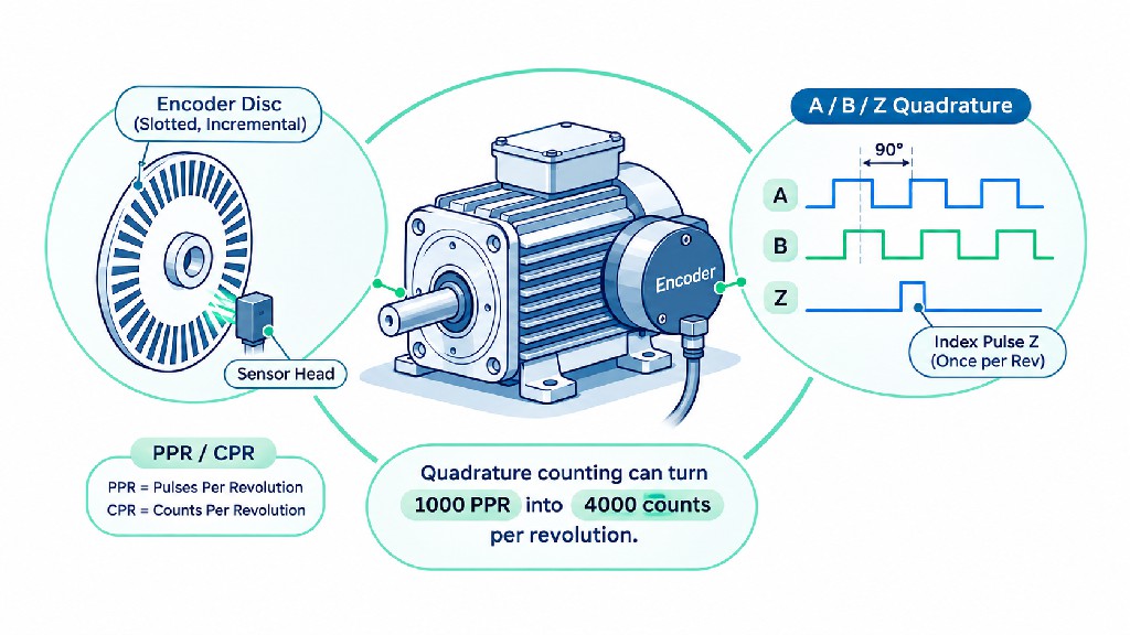
A standard two-channel incremental encoder produces square-wave signals A and B. These signals are shifted by one-quarter of an electrical signal period, usually described as 90 electrical degrees of quadrature. By observing which channel leads, the receiver determines direction. Counting selected edges provides a measurement of movement. Some models add an index channel, Z, that produces a reference event approximately once per mechanical revolution.
Incremental encoders are popular because they can be compact, affordable and straightforward to integrate with controllers that already include quadrature-decoder inputs. They are often well suited to speed measurement, closed-loop steppers, general positioning machines, conveyors and test fixtures. They also offer a wide choice of resolution and electrical output styles.
The principal limitation is not that incremental encoders are inherently inaccurate. Rather, they do not provide an unambiguous absolute position at an arbitrary moment solely from A/B pulses. After startup, the controller must establish a known position using a homing switch, reference mark, stored position with a justified retention method, or another referencing strategy. If movement occurs while the controller is off, unobserved motion cannot be reconstructed merely by reconnecting A/B signals.
An encoder's Z pulse helps establish a repeatable rotational reference, but the controller still needs to know which revolution or machine datum is relevant. A motor can make many turns while moving an axis. Finding one index event does not, by itself, identify the machine's safe home point or the correct turn number.
Advantages of Incremental Encoders
Incremental feedback offers a good cost-to-function balance when the machine can home safely and the drive supports quadrature inputs. The signal chain is transparent enough to diagnose using a counter or oscilloscope. Incremental devices can provide high update rates, and the controller can estimate speed by measuring pulse frequency or edge timing. They are particularly useful when a replacement is needed for an existing A/B encoder system.
Limitations of Incremental Encoders
Position counting can be corrupted by missed edges, noise, invalid transitions or incorrect direction configuration. Higher PPR raises the input-frequency requirement. The encoder may require extra wires for differential outputs and an index. Above all, its count is relative to the chosen datum, so safe restart procedures must be designed deliberately.
For an actual catalog example, FRANK HU MOTOR offers a , listed with a 1000 PPR incremental optical encoder. This illustrates a common motor-plus-feedback package, but its encoder output characteristics still need to be matched to the intended driver.
Absolute Encoders: Position Immediately After Power-Up
An absolute encoder associates each position in its specified range with a unique digital code. When the drive reads the encoder, it receives a position value rather than having to infer the position by counting every movement since initialization. This is especially useful when a machine cannot safely execute a conventional homing move after startup, or when losing position would cause lengthy recovery.
For example, a robot joint located close to a mechanical stop may not have enough clearance for a routine homing cycle. A packaging machine may have a complex phased mechanism that should resume in a known angular relationship. A servo-driven tool magazine may need to know where it stopped after a power interruption. In such situations, absolute feedback can simplify startup and reduce operational disruption.
However, the phrase absolute encoder does not mean the entire machine always knows its position. The encoder may report only the angular position of the motor shaft. If a gearbox slipped, a coupling loosened, a belt skipped or an axis moved relative to its motor, the reported motor angle may not equal the true output location. The controller also must know the relationship between encoder zero and the machine datum.
Furthermore, the controller needs to read and interpret the encoder's digital protocol correctly. Nominal resolution alone cannot establish compatibility. Motor commutation may require additional phase alignment, motor data or an appropriate absolute rotor angle from startup.
explains that absolute position codes can eliminate an ordinary home cycle, and describes both single-turn and multi-turn options. identifies common serial interfaces including SSI, BiSS, EnDat and Hiperface.
Advantages of Absolute Encoders
Absolute feedback can reduce or eliminate the need to establish shaft position through movement on each startup. It is valuable for multi-axis automation, robotics, servo positioning, equipment that must recover after interruptions and machines where homing takes significant production time. Depending on the encoder and drive, the digital interface may also communicate diagnostics, temperature or device identity.
Limitations of Absolute Encoders
Compared with a simple incremental solution, a suitable absolute system can involve additional protocol constraints, commissioning steps, drive dependencies and higher component costs. Not every drive accepts every serial interface. Multi-turn retention can require batteries, energy-harvesting electronics or mechanical gearing. Those differences affect maintenance and reliability and must be verified in the exact datasheet.
Single-Turn vs Multi-Turn Absolute Encoders
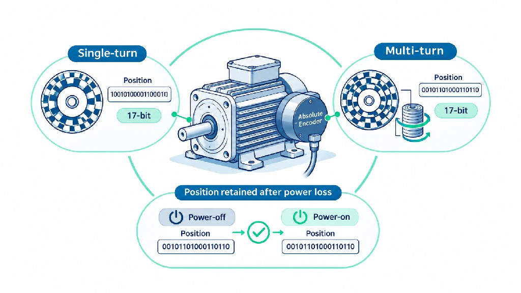
An absolute single-turn encoder reports a unique angular position within one mechanical revolution. For example, it may distinguish 0–360 degrees with 12, 17 or 23 bits of nominal position coding. When the shaft returns to the same angular location after one full revolution, a single-turn encoder reports the same position value again. It cannot, by itself, determine whether the shaft has completed zero, one or several full turns.
An absolute multi-turn encoder combines the angular position within the current turn with information about how many turns have occurred over its supported multi-turn range. That extra information is particularly valuable for ballscrews, hoists, conveyors, actuators and robot mechanisms where the machine's position spans multiple motor revolutions.
Consider a screw-driven stage with a 5 mm lead. A single-turn encoder reading 90 degrees could correspond to 1.25 mm, 6.25 mm, 11.25 mm, or many other locations separated by 5 mm. The same shaft angle does not reveal the screw's turn number. A functioning multi-turn system can distinguish those positions if the total travel is within its configured measuring range and the motor-to-load connection has remained valid.
| Feature | Single-turn absolute | Multi-turn absolute |
|---|---|---|
| Reported position | Angle within one revolution | Angle plus revolution count |
| Identifies how many complete turns occurred | No | Yes, within supported range |
| Useful for direct-drive rotary tables | Often | May be unnecessary |
| Useful for long screw-driven positioning axes | Only with other turn tracking/reference | Often preferable |
| Power-off movement handling | Returns current single-turn angle | Depends on multi-turn retention technology |
| Key specification | Bits per revolution | Bits per revolution and turn-count range |
Multi-turn retention is not identical across products. Some units use a battery-backed counter; others use a geared mechanical code, Wiegand energy harvesting or another batteryless method. Buyers should request explicit evidence of whether the encoder retains the turn count when the machine is de-energized and the shaft continues to move. A drive may also impose its own restrictions on battery alarms, initial setup and restoration procedures.
A useful illustration is , which distinguishes single-turn position measurement from multi-turn measurement that also tracks revolutions. The right choice depends on the number of revolutions the application must distinguish, not merely the total number of resolution bits printed on the label.
Optical, Magnetic and Hall-Effect Sensing: Three Different Ideas
Sensing method is independent of position-output type. This point is critical because buyers often use magnetic encoder and Hall sensor as though they mean the same thing.
Optical Motor Encoders
An optical rotary encoder normally uses a patterned disk, light source and photodetectors to convert shaft rotation into detectable changes. Optical encoders may produce incremental quadrature output or a coded absolute position. They can achieve fine signal patterns and are common in precision servos and closed-loop stepper packages.
Optical sensing is attractive where repeatable, high-resolution measurement is important, but packaging matters. Contamination, condensation, mechanical shock, disk alignment and operating temperature should be assessed against the construction and ingress protection of the actual encoder. It would be incorrect to assume that every optical encoder is fragile: industrial sealed products are available for demanding environments.
Magnetic Motor Encoders
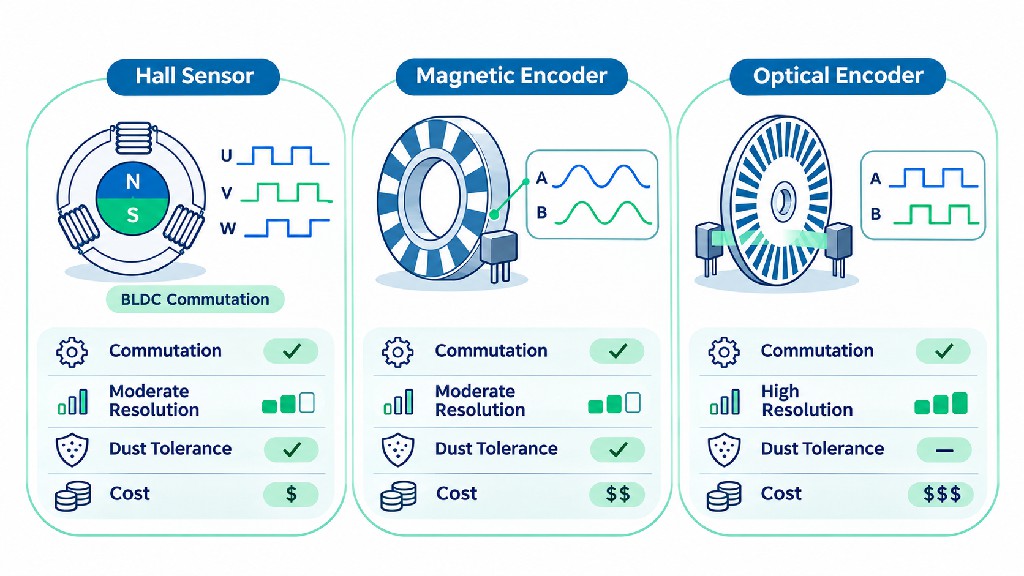
A magnetic encoder senses changes in magnetic field caused by a rotating magnet or patterned magnetic target. Some designs use Hall-effect sensing; others use magnetoresistive or related technologies. With suitable electronics, a magnetic device can deliver incremental A/B output, an analog angle signal, PWM, or an absolute digital angle. A high-resolution magnetic position sensor should not be confused with three coarse commutation Hall switches.
Magnetic technologies can offer compact construction and resistance to optical contamination. They may be attractive in small integrated motors, compact robot joints and spaces where a glass code disk is inconvenient. Yet magnetic field disturbances, sensor-magnet alignment, air gap, eccentricity, temperature and neighboring motor magnets can influence performance. A precise resolution figure is not proof of equally precise angle accuracy.
Three Digital Hall Sensors for BLDC Commutation
Many sensored BLDC motors use three digital Hall-effect devices positioned to provide rotor-sector information. In a conventional six-step commutation system, the three signals generate six valid combinations during one electrical cycle. Each transition is separated by 60 electrical degrees, not necessarily 60 mechanical degrees.
Electrical angle depends on the motor's number of pole pairs:
Electrical angle = Mechanical angle × Number of pole pairs
For a four-pole-pair motor, a 60-electrical-degree sector corresponds to only 15 mechanical degrees. The six-state sequence repeats four times in one mechanical revolution. This provides useful commutation information but is very coarse compared with a high-resolution position encoder.
Texas Instruments documents this six-state arrangement in its , including the relationship between Hall signals and 60-degree electrical sectors. A motor controller may estimate speed between transitions or interpolate angle, but interpolation is not the same as directly measuring every intermediate shaft position.
Optical vs Magnetic vs Basic Hall Feedback
| Attribute | Optical encoder | High-resolution magnetic encoder | Three digital Hall switches |
|---|---|---|---|
| Primary sensing mechanism | Light and patterned disk | Magnetic angle or target sensing | Magnetic-field state switching |
| Incremental option | Yes | Yes, for suitable models | Coarse state transitions, not standard A/B by default |
| Absolute position option | Yes, for suitable models | Yes, for suitable models | Only a coarse electrical sector unless supplemented |
| Typical selection driver | Fine feedback and established industrial solutions | Compact integration and suitable environment | Basic sensored BLDC commutation |
| Main design concern | Contamination protection, alignment, construction | Magnet installation, stray fields, calibration | Electrical phasing, sector granularity, wiring |
| Can all versions replace a servo encoder? | No | No | Generally no |
The right comparison is between actual devices with stated specifications for accuracy, speed, latency and robustness, not between broad sensing labels alone.
Hall Sensor vs Encoder for BLDC Motors
When selecting an encoder for BLDC motor applications, first establish how the controller drives the motor. Six-step trapezoidal control commonly works with three Hall signals. More demanding sinusoidal control or field-oriented control (FOC) may use a high-resolution position sensor, but some FOC drives also operate sensorlessly or use Hall-assisted estimation. The required sensor depends on the specific algorithm, operating speed, startup torque and control performance.
For a ventilation fan that starts easily and runs at constant speed, sensorless operation may avoid additional wiring. For a conveyor expected to start with load at low speed, Hall sensors can help the drive establish commutation sectors. For a robot wheel, a packaging axis or a BLDC-powered positioning stage, an incremental or absolute encoder may provide better information for speed and position loops.
There is an additional distinction between knowing which motor phases to energize and knowing where the output must stop. Three Hall sensors can tell a six-step drive which commutation sector is active. That does not mean a machine can resolve a tiny move or recover a precise mechanical home point. Applications that require both smooth low-speed torque and accurate endpoint positioning should evaluate feedback and motor control together.
| BLDC requirement | Feedback candidate | Important trade-off |
|---|---|---|
| Constant-speed blower | Sensorless or Hall | Cost vs start reliability and operating range |
| Loaded conveyor start | Three Hall sensors | Robust initial sector detection, coarse position |
| Variable-speed pump | Hall, sensorless or encoder | Depends on speed range and torque response |
| Precise indexer | Incremental or absolute encoder | Added cost, stronger positional feedback |
| High-performance FOC at zero/low speed | Drive-compatible rotor-angle encoder or suitable sensor | Accurate electrical phase information and commissioning |
| AGV traction wheel | Hall or encoder, depending on drive and odometry | Wheel feedback alone does not eliminate slip |
A sensored BLDC drive that expects Hall inputs cannot necessarily read A/B quadrature in place of those Hall signals. Conversely, a servo drive expecting a serial absolute encoder cannot be made compatible with three Hall switches simply by matching supply voltage. A combined feedback package is possible, but the motor and driver must be engineered for it.
Quadrature Encoder Signals: A, B and Z Explained
An incremental quadrature encoder generally provides channels A and B. Their phase difference encodes direction. For one valid rotation direction, the state sequence might be 00 → 01 → 11 → 10 → 00; reversing the direction reverses the order. The actual interpretation depends on whether A or B leads and on the controller's sign setting.
The optional Z channel, also called the index or reference channel, indicates a designated rotational position once per encoder shaft revolution in many standard designs. Its pulse width and relation to A/B are manufacturer-dependent. The Z event can make fine reference alignment repeatable after an initial homing operation, but it is not an absolute turn counter.
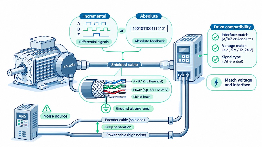
Some encoders provide complementary outputs such as A+, A−, B+, B− and Z+, Z−. These are particularly useful for differential receivers and electrically noisy installations. Others supply only A, B, power and ground. Never infer an index channel from a marketing phrase such as three-channel motor feedback without reviewing the connector pinout.
The Difference Between x1, x2 and x4 Decoding
The controller decides how many changes to count:
-
x1: count one selected edge per A-channel period.
-
x2: count the rising and falling edges of one channel.
-
x4: count the rising and falling edges of both A and B.
In the usual definition where PPR is the number of complete A-channel cycles per mechanical revolution, a 1000 PPR encoder yields 1000, 2000 or 4000 counted positions per revolution under x1, x2 or x4 decoding respectively. This factor comes from decoding the existing signal edges; the encoder has not magically produced four times as many physical lines.
The manufacturer explicitly explains that x4 logic is implemented by the controller. The defines PPR on an incremental channel and quadrature-decoded CPR as PPR multiplied by four in that context.
The edge decoding must work correctly at the machine's highest operating speed. If the decoder misses transitions, the displayed count and real shaft position diverge. This is a performance and signal-integrity issue, not a nominal resolution issue.
PPR vs CPR vs Counts per Revolution: Avoid This Purchasing Mistake
PPR (pulses per revolution) usually means the number of complete signal cycles on one incremental channel per mechanical turn. CPR (counts per revolution) often means the number of quadrature-decoded counts per turn. LPR (lines per revolution) often refers to physical or electrical signal periods on a graduated encoder disk, especially in optical or sine/cosine contexts. These meanings are common but not universal.
Some catalogs use CPR for cycles per revolution rather than counts per revolution. Others use resolution to mean effective count increments after interpolation. As a result, 1000 CPR may not describe the same hardware across two suppliers. Always ask the vendor what exactly is being counted and how the receiving controller interprets it.
| Encoder specification, assuming standard quadrature terminology | x1 counts/rev | x2 counts/rev | x4 counts/rev | Nominal angle per x4 count |
|---|---|---|---|---|
| 100 PPR | 100 | 200 | 400 | 0.900000° |
| 500 PPR | 500 | 1,000 | 2,000 | 0.180000° |
| 1,000 PPR | 1,000 | 2,000 | 4,000 | 0.090000° |
| 2,500 PPR | 2,500 | 5,000 | 10,000 | 0.036000° |
| 5,000 PPR | 5,000 | 10,000 | 20,000 | 0.018000° |
These are mathematical count increments, not measured absolute position errors. They assume standard PPR terminology, proper x4 decoding, stable signals and one mechanical revolution at the encoder shaft.
A second source of confusion is microstepping. A 1.8-degree stepper has 200 nominal full steps per revolution. A driver set to 16 microsteps per full step commands 3200 microstep intervals per revolution. If that motor has a 1000 PPR encoder decoded at x4, its feedback has 4000 counts per revolution. The number 3200 describes commanded electrical subdivisions; 4000 describes encoder decoding. Neither guarantees 3200 or 4000 equally accurate mechanical stop positions.
The critical procurement requirement is to specify both the encoder's native output definition and the drive's counting mode. If the vendor quotes only “high-resolution 4000 CPR feedback,” request confirmation whether it is 1000 PPR x4, 4000 PPR x1, or something else.
Understanding Absolute Encoder Bits: What Does 17-Bit Really Mean?
An absolute encoder's single-turn resolution is commonly expressed as the number of bits used to represent angular positions within one revolution. An ideal 17-bit single-turn position value has 2^17 = 131,072 distinguishable codes. Dividing 360 degrees by this number gives approximately 0.0027466 degrees per code, or about 9.89 arcseconds per code.
It is tempting to convert that number directly into an accuracy promise. Do not. An encoder can output a very fine digital position word while still having larger systematic angle error due to its sensor, magnet or disk alignment, electronic interpolation, mechanical mounting or calibration. The servo motor can also have bearing runout, shaft compliance and a coupling or load with its own error sources.
| Single-turn resolution | Nominal positions per revolution | Nominal degrees per position |
|---|---|---|
| 10 bit | 1,024 | 0.3515625° |
| 12 bit | 4,096 | 0.0878906° |
| 14 bit | 16,384 | 0.0219727° |
| 16 bit | 65,536 | 0.0054932° |
| 17 bit | 131,072 | 0.0027466° |
| 20 bit | 1,048,576 | 0.0003433° |
| 23 bit | 8,388,608 | 0.0000429° |
These values are calculated directly from 360° / 2^bits. They are theoretical position-code increments, not verified mechanical accuracy specifications. A high-resolution feedback system may nonetheless be worthwhile for smooth servo control and high-quality velocity estimation when the entire system is designed appropriately.
A 17 bit absolute encoder can be attractive for compact DC servo axes where the drive supports the feedback protocol and the mechanical design does not demand a more elaborate sensor. FRANK HU MOTOR's lists examples of DC servo models advertised with 17-bit absolute feedback and AC servo models advertised with 23-bit absolute feedback. These listings demonstrate options available in the catalog; purchasers should confirm the exact encoder protocol, number of turns, cable assembly and matching drive for the specific part number before specifying a replacement or ordering a system.
For a multi-turn encoder, be careful about bit allocation. A product described as “17-bit single-turn plus 16-bit multi-turn” is not the same as a product with “17-bit total resolution.” The first description suggests 131,072 position codes per turn and an additional turn-counter field of up to 65,536 states, subject to the maker's signed range and configuration. The second may divide its bits between angle and turn count. Request the data format and maximum measuring range.
Encoder Resolution Is Not Mechanical Accuracy
Resolution is the smallest change the measurement system can represent under its defined decoding. Accuracy describes closeness to the true position. Repeatability describes how consistently a system returns to a given position under stated conditions. Precision, hysteresis, linearity, backlash and following error describe different aspects of performance. Purchasing decisions become unreliable when these terms are treated as synonyms.
Suppose a motor encoder provides 4000 decoded counts per turn. One count represents 0.09 degrees of motor rotation. Imagine that the motor drives a ballscrew with a 5 mm lead. The ideal linear increment represented by one feedback count is just 5 mm / 4000 = 0.00125 mm, or 1.25 micrometers. This is useful as a measurement granularity estimate. It does not mean the axis can position to 1.25 micrometers.
If the screw has lead error, the coupling twists, the guide has friction, the bearings shift under load, or backlash changes with direction, the actual carriage can be farther from the requested position than one encoder count. Thermal expansion can also produce meaningful travel errors. At higher speed, servo following error and structural vibration add further uncertainty.
Dynapar's explicitly warns that finer resolution cannot correct systematic error. For direct linear measurement, explains that mounting location and guideway error affect measurement accuracy.
The Error Budget That Buyers Should Request
A meaningful axis performance statement requires more than a resolution figure. Ask for a defined error budget that considers the feedback sensor's accuracy, sensor mounting, motor positioning performance, mechanical transmission, thermal conditions, loading, motion profile and control tuning. Different errors combine in different ways; do not simply add unqualified catalog numbers or assume they cancel.
For a high-value CNC application, a practical acceptance test might specify bidirectional positioning accuracy over the machine's working travel, repeatability after repeated moves, maximum following error during a representative trajectory and results at a defined ambient temperature. Record the measuring method and instrument. A high-bit encoder is one component in satisfying that test, not a substitute for the test itself.
Motor-Shaft Encoder vs Load-Side Encoder
Mounting location determines what errors the feedback system can observe. A motor-shaft encoder is a natural choice for commutation and a fast inner speed loop. It measures the rotor directly, avoiding uncertainty from the transmission when the controller needs rotor angle. This makes it central to many servo and closed-loop stepper packages.
But the motor shaft is not always the element that matters to the customer. Consider a robot arm with a gearbox. The motor encoder can report a perfectly stable angle while the output joint changes slightly due to gear compliance. A belt-driven gantry can experience belt stretch that is not visible at the motor. A screw-driven CNC axis can have pitch and thermal errors that a motor encoder does not directly detect.
A load-side encoder or linear scale measures movement after some or all of those transmission elements. When the controller supports suitable feedback architecture, it may use motor feedback for commutation and high-speed regulation while using load feedback for the outer position loop. This is often called dual-loop or full-closed-loop control, although naming and details vary by controller manufacturer.
| Feedback position | Directly observes | Does not directly observe | Typical purpose |
|---|---|---|---|
| Motor rotor | Shaft angle and speed | Backlash or lost motion after coupling | Commutation, servo speed and motor position |
| Gearbox output | Output rotation | Further downstream belt or leadscrew error | Robot joint or geared-axis positioning |
| Ballscrew end | Screw rotation | Screw lead error and carriage thermal drift | Axis monitoring where linear scale is impractical |
| Linear scale on carriage | Actual carriage displacement at scale location | Tool-tip deflection or Abbe offset elsewhere | Precision CNC and metrology axes |
One important caveat: adding a second encoder does not automatically improve performance. Dual-loop tuning can be difficult when a transmission is elastic, has backlash or contains resonant modes. The drive must support the configuration and the system integrator must tune it. In some machines, a well-engineered single-loop drive with a sufficiently accurate mechanical system will be more economical and reliable.
Encoder Resolution Calculator: Formulas You Can Use Before Ordering
An Encoder Resolution Calculator is a practical purchasing aid because it connects encoder specifications to real motion distances, input bandwidth and application requirements. The following calculations can be implemented in a website calculator, engineering spreadsheet or controller configuration tool.
Incremental Encoder Counts per Revolution
For standard incremental quadrature output:
Effective counts/rev = PPR × decoding factor
Use a factor of 1, 2 or 4 for x1, x2 or x4 decoding. First confirm that the encoder maker uses PPR for the number of complete cycles on one channel.
Angular Increment per Count
Angular increment (degrees) = 360 / effective counts/rev
For 1000 PPR x4: 360 / 4000 = 0.09° per count.
Absolute Encoder Angular Increment
Absolute angular increment (degrees) = 360 / (2^single-turn bits)
For 17 bits: 360 / 131072 ≈ 0.0027466° per code.
Linear Distance per Feedback Count
For a direct motor-to-screw system with one screw revolution per motor revolution:
Linear increment (mm/count) = screw lead (mm/rev) / motor counts/rev
With a gearbox, define R as motor revolutions per one output revolution:
Linear increment (mm/count) = screw lead / (motor counts/rev × R)
For a 5 mm screw lead, 1000 PPR x4 and a direct coupling, the ideal result is 5 / 4000 = 0.00125 mm/count. If a 5:1 reduction gearbox drives the screw, the ideal calculation becomes 5 / (4000 × 5) = 0.00025 mm/count; gearbox backlash and compliance may dominate the achievable accuracy.
Rotary Output Increment After a Gearbox
Output angular increment (degrees/count) = 360 / (motor counts/rev × R)
A 1000 PPR x4 encoder with a 10:1 gearbox gives 360 / (4000 × 10) = 0.009° of ideal output rotation per motor count. That does not establish gearbox output accuracy or repeatability.
Encoder Frequency and Maximum Motor Speed
For incremental channel A:
A-channel cycle frequency (Hz) = PPR × motor RPM / 60
The approximate x4 decoded event rate is:
Decoded edge rate (counts/s) = 4 × PPR × motor RPM / 60
For a 2500 PPR encoder at 3000 rpm, each channel runs at 125,000 cycles/s (125 kHz) and the x4 decoder processes up to 500,000 count events/s in the normal idealized model. The drive's quadrature input, line receiver and signal processing must support the relevant rates. Encoder output-frequency limits, cable effects and minimum pulse widths also matter.
Calculator Input and Output Design
| Calculator input | Suggested field | Why it matters |
|---|---|---|
| Feedback type | Incremental / absolute | Determines counting formula |
| Native PPR or single-turn bits | Positive integer | Defines nominal sensor code density |
| Quadrature mode | x1 / x2 / x4 | Defines decoded count density |
| Maximum motor speed | RPM | Helps validate input-frequency capability |
| Screw lead | mm per output revolution | Converts rotation to travel |
| Gear reduction | Motor revolutions per output revolution | Converts motor feedback to output travel |
| Maximum decoded input rate | Counts per second, if applicable | Identifies counter overload risks |
| Calculator output | Interpretation |
|---|---|
| Counts or codes per motor revolution | Native or decoded angular granularity |
| Motor angular increment | Theoretical degrees per count/code |
| Output angular increment | Theoretical gear-reduced granularity |
| Linear travel per count | Theoretical movement represented by one code |
| A-channel frequency | Required signal frequency at chosen speed |
| Decoded count-event rate | Approximate processing rate for quadrature receiver |
| Warning | “Resolution is not positional accuracy” |
A public calculator should show its assumptions and use explicit terms rather than a single ambiguous “resolution” field. It should not output an accuracy claim or guarantee that a motor-drive combination can attain the calculated increment. An advanced version could add motor inertia, maximum frequency, mechanical accuracy and a calculated safety margin, but these must be clearly separated from the basic count math.
Electrical Interfaces: Compatibility Matters More Than a Shared Connector
Two encoders can look physically identical and still be incompatible with the same drive. Check both the electrical layer and the information protocol. The connector shape is not a trustworthy substitute for a wiring diagram or supported-encoder list.
Single-Ended Incremental Outputs
A single-ended A/B output uses each signal relative to a common reference. Some designs use push-pull outputs; others use open-collector outputs with suitable pull-ups. Output voltage, current capacity, logic thresholds and maximum frequency must match the receiving input. A 5 V output is not automatically safe for a controller whose input is limited to 3.3 V. Similarly, an open-collector sensor may not work correctly without the intended pull-up arrangement.
Differential Incremental Outputs
Differential encoder systems may use A+/A−, B+/B− and optionally Z+/Z− pairs, frequently with RS-422-compatible line drivers. The receiving circuit senses the difference within each pair, improving immunity to electrical interference compared with a simple single-ended connection in many industrial installations. Differential communication still needs suitable twisted pairs, correct termination where specified and a common-mode voltage within the receiver's limits.
Encoder Products Company's discusses differential line-driver outputs and noise immunity. The corresponding gives installation guidance for routing, grounding, shielding and avoiding ground-current problems.
Absolute Serial Protocols
Common absolute feedback interfaces include SSI, BiSS-C, EnDat and Hiperface, alongside proprietary servo feedback protocols. These names do not indicate universal compatibility. A drive may support one version but not another, require a particular position word length, insist on encoder identification or expect a specific cyclic data format. Some motor feedback links include parameter memory, diagnostics, temperature or commutation data.
The describes the protocol's synchronous real-time transfer and associated register communication. The are relevant when engineers need to verify actual protocol requirements. Always use the documentation for the specific encoder and drive models, not merely a generic claim that both support “serial feedback.”
Hall Inputs and Analog Feedback
Three Hall signals typically connect to dedicated Hall inputs on a BLDC drive. Phase order, supply voltage, pull-up requirements, Hall polarity and relative alignment to the motor's electrical phase are important. Other drives may accept resolver feedback, sine/cosine encoder outputs or analog magnetic-angle signals. These cannot be assumed to plug into a standard digital quadrature input without appropriate electronics and configuration.
Electrical Noise, Cable Shielding and Grounding
Feedback cables share a machine with inverters, motor phase cables, contactors, switching supplies and other noise sources. Motor phase switching can create interference that causes false edges, communication errors or intermittent encoder faults. Problems may appear only at high speed, under heavy torque or after a long cable is installed.
Use the following engineering practices as a starting point, subject to the actual drive and encoder manuals:
-
Route feedback cables away from motor power wiring, inverter outputs and noisy switching equipment. Use separate paths where practical.
-
Use twisted pairs for the intended differential channels and a shielded feedback cable of the type specified by the equipment supplier.
-
Keep encoder cables within the specified length and capacitance limits. Do not assume that a cable rated for one signal standard is suitable for another.
-
Terminate differential lines only as required by the driver, receiver and installation scheme. Incorrect termination can create distortion rather than solve it.
-
Ground machine frames and motor housings through the protective-earth system as required by applicable electrical safety rules.
-
Follow the manufacturer's shield-bonding strategy. A single-ended shield termination may be specified for one system; another industrial design may require a different high-frequency bonding scheme. Avoid creating unintended return paths through signal shields.
-
Keep encoder supply voltage clean and within tolerance, checking for voltage drop at the far end of long cables.
-
Verify signal quality under real operating conditions, using a suitable oscilloscope, error counter or drive diagnostic page.
A final point deserves emphasis: protective earth and encoder signal common are not interchangeable concepts. Protective earth is a safety system. Signal reference and cable shield arrangements must follow the wiring design. Never disconnect protective earth merely to suppress noise. If errors persist, investigate wiring topology, coupling and grounding with a qualified controls engineer.
Matching a Stepper Motor with Encoder to Its Driver
A stepper motor with encoder is not simply an ordinary stepper with extra wires. It becomes a closed-loop system only when a compatible driver reads the feedback and uses it correctly. The motor, feedback and control algorithm form a matched combination.
In a closed-loop stepper arrangement, the driver can compare commanded motion against measured rotor movement. Depending on the product, it may correct position error, adjust current, reduce heating or issue an alarm when the motor falls behind. The available functions vary significantly. An encoder does not increase the fundamental torque capability of the motor, and not every controller can recover every lost-step event safely.
A common example is a 1.8-degree hybrid stepper paired with a 1000 PPR incremental encoder. With suitable x4 decoding, there are 4000 encoder counts per shaft revolution. This can provide useful feedback relative to the stepper's 200 nominal full-step positions. However, the driver must correctly support the encoder's voltage, A/B order, electrical output, resolution, rotation direction and fault-detection settings.
Compare options in FRANK HU MOTOR's and . Integrated packages can simplify wiring and compatibility because motor, driver and feedback are supplied as an engineered unit. A separate motor-and-drive arrangement offers flexibility but requires more integration checks.
Before purchasing, ask whether the encoder is included or optional, whether the specified PPR is native or x4 effective, whether an index channel is available, whether the encoder uses single-ended or differential A/B, and what happens if the feedback cable becomes disconnected. Also request a torque-speed curve for the exact motor and supply conditions; encoder resolution does not determine available torque at speed.
Selecting a Servo Motor Encoder for AC and DC Servo Systems
A servo motor encoder usually serves a more demanding control architecture: the drive continuously regulates current/torque, speed and position using feedback. Brushless servo motors also need reliable rotor information for electronic commutation, whether obtained from an absolute encoder, incremental feedback with suitable commutation information, a resolver or an approved sensorless/initialization method.
A servo drive may expect a precise feedback protocol, encoder identification data and an established relationship between encoder zero and the motor's electrical angle. Replacing a 17-bit encoder with a 23-bit device is therefore not automatically an upgrade. If the drive cannot decode the replacement format, or if the commutation offset is wrong, the system may not function correctly and could behave dangerously.
When comparing systems, check the rated and peak torque, rated and maximum speed, rotor inertia, motor winding voltage and current, encoder type, absolute turn-count capability, drive model, braking options, communications and environmental protection. Encoder compatibility is necessary, but it is only one part of a complete servo match.
FRANK HU MOTOR's include DC servo models marketed with 17-bit absolute encoders and AC servo models marketed with 23-bit absolute encoders. Treat these as product-specific attributes, not as a guarantee that all drives in a given voltage class use the same feedback. Request the matched drive and approved cable details for the selected SKU.
For a machine designer comparing a servo with an encoder-equipped stepper, the gives broader context on torque-speed behavior, acceleration, control and application fit.
Integrated Motors: When a Matched Feedback Package Is Better
Integrated motor units combine elements such as motor, driver, feedback device and control interface in one assembly. This can reduce cabinet space, cable count and integration work, especially for compact automation, inspection stations, laboratory devices, packaging machinery and distributed motion axes.
For buyers, integration reduces one major risk: selecting an encoder that the driver cannot read. But integrated is not synonymous with universal. The module still needs the correct power supply, motion command interface, rated torque and speed, cooling, protection rating and fault behavior. Ask how configuration parameters are saved, how alarms are reported and whether the system preserves position after power cycling.
For an incremental-encoder integrated stepper, startup homing may still be needed even though the motor and driver are already matched. For an absolute-servo integrated system, the available position restoration behavior still depends on whether the feedback is single-turn or multi-turn and how the machine establishes its datum. Integration simplifies wiring and procurement; it does not remove the need for system engineering.
Where machine builders expect to repeat the same actuator across many units, an integrated solution may improve assembly consistency and simplify spares. Where the project requires nonstandard motor windings, a special shaft, a remote encoder or an unusual interface, a more modular OEM configuration may be preferable.
Motor, Encoder and Drive Compatibility Checklist
A complete feedback system should be specified as three connected products, not three unrelated model numbers. Use this compatibility matrix when discussing a quotation, replacement or OEM design.
| Check | Questions the supplier should answer | What can go wrong if ignored |
|---|---|---|
| Motor type | Stepper, BLDC, AC servo or DC servo? Pole count or pole pairs? | Incorrect commutation and control mode |
| Encoder output | A/B/Z, Hall, SSI, BiSS-C, EnDat or proprietary? | Drive cannot decode feedback |
| Resolution format | Native PPR, x4 CPR, bits/turn and multi-turn bits? | Wrong electronic gearing and scaling |
| Supply and logic | Encoder voltage, current, thresholds and output stage? | Electrical damage or missed signals |
| Maximum speed | Encoder mechanical RPM and electrical bandwidth? | Lost edges or feedback alarms |
| Motor phase alignment | Hall sector sequence or encoder commutation offset? | Vibration, poor torque or unsafe behavior |
| Mechanical fit | Shaft, bore, mounting, concentricity and axial clearance? | Misalignment, wear or sensor error |
| Cable and connector | Pinout, twisted pairs, length, shielding, termination? | Intermittent faults and noise |
| Environmental rating | Temperature, shock, vibration, dust and moisture? | Premature failure or unstable feedback |
| Absolute position | Single-turn or multi-turn, turn retention, battery policy? | Unexpected homing or position loss |
| Drive firmware | Supported encoder protocol/version and parameter settings? | Incompatible or unreliable operation |
| Safety | Safe motion requirements, faults, brakes and limits? | Inadequate machine protection |
| Documentation | Datasheets, wiring diagrams, setup and test reports? | Higher integration and maintenance costs |
A motor with a brake deserves particular care. A holding brake is usually designed to hold an already-stopped load, not to provide routine dynamic braking. The presence of an absolute encoder does not eliminate gravity or stored-energy hazards on vertical axes. Safe torque off, safe motion functions, mechanical stops and independent protective devices must be specified and validated as required by the machine risk assessment.
Four Real-World Selection Examples
Example 1: NEMA 17 Closed-Loop Stepper for a Small CNC or Dispensing Axis
Application: a compact axis must repeatedly move between set points, with moderate speed and a controlled homing procedure. The main purchasing priorities are manageable cost, simple step-and-direction control and the ability to detect excessive position error.
Candidate approach: a NEMA 17 stepper with a 1000 PPR incremental encoder and a compatible closed-loop stepper driver. Under x4 decoding, the controller can use up to 4000 counts per motor revolution. With a 5 mm direct-drive screw lead, the theoretical encoder measurement increment is 1.25 µm.
Important limitation: 1.25 µm is not the machine's proven accuracy. Screw pitch error, compliance, guide friction, backlash and controller tuning still need evaluation. If the application requires verified micron-level positioning over a long travel, a calibrated stage or load-side scale may be necessary.
Buying decision: prefer a matched feedback-and-drive package when commissioning time matters. Confirm A/B wiring, encoder voltage, the drive's accepted PPR range and position-error alarm settings. FRANK HU MOTOR's is one reference point for the motor-side specification.
Example 2: BLDC Motor for an AGV or Warehouse Wheel Module
Application: an AGV wheel drive needs reliable low-speed starting, variable speed and feedback for motion control. Cost and installation simplicity matter, but the machine also needs repeatable speed behavior while moving a changing load.
Candidate approach: three Hall sensors may be adequate for a basic sensored commutation controller. An incremental encoder or a drive-supported magnetic angle sensor becomes attractive when the motion controller needs finer wheel speed or position measurements. The correct solution depends on the drive architecture, required low-speed smoothness and allowable cost.
Important limitation: measuring wheel revolutions does not measure true vehicle travel when wheels slip. AGV navigation may also use inertial sensors, cameras, lidar and other localization methods. An expensive wheel encoder alone cannot remove floor traction errors.
Buying decision: specify the motor pole pairs, drive commutation mode, gearing, wheel diameter, minimum operating speed, available input channels and desired feedback update behavior. Ask whether an encoder can be added without changing the driver and whether the same sensor supports both commutation and wheel odometry.
Example 3: Compact DC Servo with 17-Bit Absolute Feedback
Application: an inspection instrument requires smooth positioning, controlled startup and a small motor package. The supplier offers a compact DC servo with a 17-bit absolute feedback specification.
Candidate approach: use the complete motor, encoder and matching drive combination. At 17 bits, the ideal position coding is 131,072 codes per mechanical turn, corresponding to roughly 0.0027466 degrees per code. The high count density supports fine position reporting, subject to actual sensor and loop performance.
Important limitation: if the feedback is single-turn, it cannot distinguish several complete shaft revolutions after a restart. A ballscrew axis may still need a reference strategy. The numerical angular increment also does not establish the stage's mechanical accuracy.
Buying decision: request confirmation of single-turn or multi-turn capability, exact serial interface, rated speed, absolute-position initialization, brake requirements and approved cable. Compare the available and specify the exact SKU rather than assuming all 17-bit drives are interchangeable.
Example 4: Industrial CNC Servo with a Load-Side Linear Scale
Application: a larger CNC machine must maintain a defined positioning tolerance across travel, changes in temperature and direction reversals. The servo motor already includes high-resolution feedback, but the mechanical transmission contributes significant error.
Candidate approach: retain the motor encoder for commutation and inner-loop regulation, and evaluate a suitable linear scale on the actual machine axis. Configure full-closed-loop or dual-loop positioning only if the drive/controller supports it and the system can be tuned safely.
Important limitation: an axis scale does not measure tool deflection or every possible geometric error. Scale alignment, thermal conditions, structural stiffness, controller tuning and measurement methodology remain important.
Buying decision: define the required axis accuracy and repeatability first. Then select the scale accuracy grade, feedback interface, environmental protection and controller architecture. Do not purchase a higher-bit servo encoder as the only remedy for screw lead error or backlash.
How to Evaluate Total Cost, Not Just Encoder Unit Price
The lowest quoted encoder price can create a costly system if it requires an additional interface card, special cable assembly, extra homing hardware or substantial commissioning time. Conversely, paying for multi-turn absolute feedback on a low-cost fan may offer no practical benefit. A useful commercial comparison considers total installed cost and the effect on production.
A simple purchasing model is:
Total system cost = sensor and motor + matched drive + cabling and mounting + commissioning + maintenance + expected downtime exposure
This is a comparison framework, not a universal cost formula. Actual values are project-dependent. Ask suppliers to quote the complete usable feedback chain. For a repetitive OEM build, compare assembly time, connector count, replacement availability and documentation consistency. For a high-duty machine, consider lost production after power failures and the frequency of required re-homing.
Absolute feedback can deliver an economic benefit if it avoids long startup sequences or prevents loss of setup. A simple incremental encoder can remain economically superior where homing is quick and safe. A Hall-only BLDC solution may be optimal when exact shaft positioning has no value to the process. The strongest specification is the one that explains which requirement creates the financial justification.
Common Encoder Selection Mistakes and How to Avoid Them
Mistake: interpreting 1000 PPR as 1000 total usable counts in every drive. Clarify the x1/x2/x4 decoding mode. In standard x4 quadrature operation, 1000 PPR yields 4000 decoded counts.
Mistake: treating 17-bit resolution as 17-bit machine accuracy. Verify angle accuracy, motor performance, mechanical transmission and load-side measurement. Bits alone cannot establish positioning tolerance.
Mistake: calling every Hall device a low-resolution encoder. Three digital Hall switches provide coarse rotor-sector information; a Hall-based magnetic angle sensor can be a much more sophisticated position device.
Mistake: assuming an absolute encoder automatically preserves every turn. Single-turn and multi-turn functions differ. Confirm the power-off turn-count method and measuring range.
Mistake: replacing a servo encoder by voltage alone. Protocol, wiring, firmware, data format and commutation alignment are essential. Matching the supply voltage is insufficient.
Mistake: selecting maximum PPR without checking speed. Higher PPR increases signal cycles and decoded event rate at a given RPM. Validate the encoder output and controller input bandwidth.
Mistake: neglecting cable quality. A feedback package that works on a bench may fail after installation beside inverter power wiring. Specify cable construction, routing, grounding and electrical tests.
Mistake: measuring only the motor when output accuracy matters. Backlash and compliance may hide behind perfect motor feedback. Consider load-side measurement where justified.
Mistake: confusing encoder feedback with functional safety. An encoder does not by itself provide safe stopping, safe position, safe speed or brake control. Safety functions require appropriately specified and validated architecture.
Mistake: ordering before agreeing on documentation. Request datasheets, pinouts, protocol details, operating limits, drawings and a matching-drive list. A technically clear RFQ usually prevents more delays than a last-minute discount saves.
Frequently Asked Questions About Motor Encoder Types
What are the main types of motor encoders?
At the highest level, motor encoders are commonly divided into incremental and absolute devices according to the position information they provide. Absolute encoders are further classified as single-turn or multi-turn. Optical and magnetic describe sensing technologies, while quadrature, SSI, BiSS-C and other names describe electrical outputs or communication protocols. Hall switches are commonly used as basic BLDC rotor-position sensors but are not equivalent to a high-resolution position encoder.
What is the difference between an incremental and an absolute encoder?
An incremental encoder reports changes in position and generally needs a reference to establish machine coordinates after startup. An absolute encoder reports a unique position within its supported measuring range when read. A single-turn absolute device knows angle within one turn; multi-turn feedback can also retain revolution information under the conditions supported by its design.
Is a 1000 PPR encoder the same as a 4000 CPR encoder?
Often, yes when CPR means decoded counts per revolution and the controller uses x4 quadrature. A 1000 PPR encoder normally provides 1000 full A-channel periods per revolution; x4 decoding counts four edges per period for 4000 counts. Because manufacturers use CPR inconsistently, always verify the precise terminology.
How accurate is a 17-bit absolute encoder?
A 17-bit single-turn position code has 131,072 possible values, equivalent to approximately 0.0027466 degrees per value. That is nominal resolution, not measured accuracy. Actual angle accuracy depends on the encoder's specifications and installation, and machine positioning accuracy depends on the entire mechanical and control system.
Can an incremental encoder work without a Z index?
Yes. A/B-only encoders can provide direction and relative motion feedback. A separate home switch or other reference mechanism can establish a machine datum. A Z channel is useful for precise rotational referencing but is not mandatory for every closed-loop system.
Can I use a Hall sensor instead of an encoder for a BLDC motor?
For basic six-step commutation, three properly phased Hall switches may be sufficient. They generally cannot replace a high-resolution encoder for precision positioning. Some BLDC drives support both Hall and encoder feedback, while others support only one type. Verify the drive's commutation and position-control capabilities.
Does an absolute encoder eliminate homing?
It can eliminate conventional shaft homing when the reported absolute position is sufficient and correctly aligned with machine coordinates. It does not automatically remove the need for an initial datum calibration, machine safety checks or position validation after mechanical changes. A single-turn encoder cannot identify the correct revolution on a multi-revolution axis without additional information.
Is an optical encoder better than a magnetic encoder?
Neither is universally better. Compare the specific products' accuracy, repeatability, resolution, speed, installation tolerances, temperature performance, shock/vibration, contamination protection and price. A well-specified magnetic encoder can outperform an unsuitable optical model for one environment, while an optical design may be preferable for another precision requirement.
Will adding an encoder turn any stepper into a servo motor?
Not automatically. Adding feedback hardware to a stepper creates a sensor-equipped motor, not a complete closed-loop system. A compatible drive must use that feedback to regulate movement and detect errors. Closed-loop steppers and conventional servo motors also differ in torque-speed behavior, motor design and control characteristics.
Do I need a motor encoder or a load encoder for a gearbox?
Motor feedback is typically essential or advantageous for fast motor regulation and electronic commutation. If accurate output-joint positioning is critical, additional load-side feedback may be justified to observe backlash or compliance. The controller must explicitly support the feedback arrangement.
How do I select an encoder for a 3000 rpm motor?
Calculate A-channel frequency as PPR × 3000 / 60; for 2500 PPR, that is 125 kHz per channel. With x4 decoding, the approximate event rate is 500,000 counts/s. Verify the encoder's electrical output limits, drive input limits, cable and mechanical RPM ratings. Then select resolution based on the required measurement granularity, not speed alone.
Can I mix an absolute encoder from one manufacturer with another servo drive?
Only if the drive officially supports that device's protocol, data framing, electrical interface, resolution, calibration requirements and commutation setup. Some systems use proprietary feedback formats or motor identification information. Obtain the drive manufacturer's approval or a verified compatibility statement before making substitutions.
How to Request the Right Motor-and-Encoder Quotation
A clear request for quotation saves time on both sides. Before asking for a price, provide the application, supply voltage, motor type, required torque and speed, duty cycle, feedback purpose, position-retention requirement, preferred interface, cable length and environmental constraints. If the encoder is replacing an existing part, include the full original part number, photographs of the connector and the drive model.
For applications with ballscrews or gearboxes, specify the reduction ratio, screw lead, travel range and required output accuracy. Say whether the quoted accuracy is a requirement to be verified through testing or merely the desired feedback count increment. For absolute feedback, specify whether position must survive power-off movement and how many revolutions must be tracked. For Hall-based BLDC systems, provide pole count and commutation requirements where known.
Copy-ready RFQ template:
Application: [CNC axis / robot joint / AGV wheel / pump / inspection stage] Motor type and size: [Stepper / BLDC / AC servo / DC servo; frame dimensions] Supply and drive: [Voltage, current limit, drive model, control mode] Required speed and torque: [Continuous, peak and duty cycle] Feedback purpose: [Commutation / speed / position / startup recovery] Encoder preference: [Incremental A/B/Z / single-turn absolute / multi-turn absolute / Hall] Resolution: [Native PPR or bits per turn, with required decoder mode] Electrical interface: [Signal levels, differential output or serial protocol] Mechanics: [Shaft, mounting, gearbox, screw lead, load-side feedback] Operating environment: [Temperature, dust, vibration, cable length] Documentation requested: [Datasheet, wiring diagram, 3D model, matching drive, test data] Quantity and customization: [Prototype volume, annual demand, OEM shaft/winding/cable changes]
FRANK HU MOTOR supports motor and drive sourcing across stepper, BLDC and servo applications. For standard products, browse the , and categories. For an OEM or ODM project, request a matched motor-feedback-drive recommendation and share the application requirements above so that compatibility can be reviewed before production.
Final Selection Recommendations
A reliable motor encoder selection begins with the machine's required behavior. Choose incremental feedback when relative motion measurement is sufficient and reliable referencing is available. Choose absolute feedback when knowing the current shaft angle at startup has value. Select multi-turn capability when the application genuinely needs the number of completed turns and confirm how those turns are retained without power. Use basic Hall sensors for BLDC commutation when they meet the control requirement, and choose more detailed feedback when the drive needs accurate speed or position information.
Match resolution to the needed measurement granularity, then check actual accuracy, speed, encoder frequency, interface support, motor phase alignment, wiring, mechanical installation and load-side errors. Never convert 4000 counts per revolution or 17-bit coding directly into a promised axis tolerance. Evaluate the complete motion-control chain.
Need help selecting an encoder-equipped motor? Explore or request a specification review for a matched stepper, BLDC or servo system. The strongest purchase is the one that delivers dependable motion, a documented electrical match and an appropriate total installed cost—not simply the highest resolution printed on the encoder label.