100W DC servo motor may be entirely sufficient for a lightweight indexing mechanism, while a poorly matched 400W DC servo motor may struggle to reach a required speed. A 750W DC servo motor may offer ample rated torque but still be unsuitable if its driver cannot support the acceleration current or absorb regenerative energy. The best solution is the motor, drive, supply, encoder and mechanical transmission working as a single system.
This DC servo motor sizing guide explains how to select a 24V servo motor or 48V DC servo motor using motion-profile calculations rather than assumptions. It covers rated and peak torque, power conversion, speed, winding and driver limitations, RMS thermal duty, inertia matching, feedback, regenerative braking, holding brakes and purchasing specifications. It also compares actual FRANK HU MOTOR products from 100W to 1000W and includes a copy-ready DC Servo Motor Sizing Worksheet for OEM engineers and equipment buyers.
The recommendations are intended for CNC machines, compact robots, AGV/AMR platforms, automated production lines, packaging machines, laboratory instruments and other equipment powered from a low-voltage DC bus. If you are still deciding between motor technologies, read our first. For specific products, browse the or the focused .
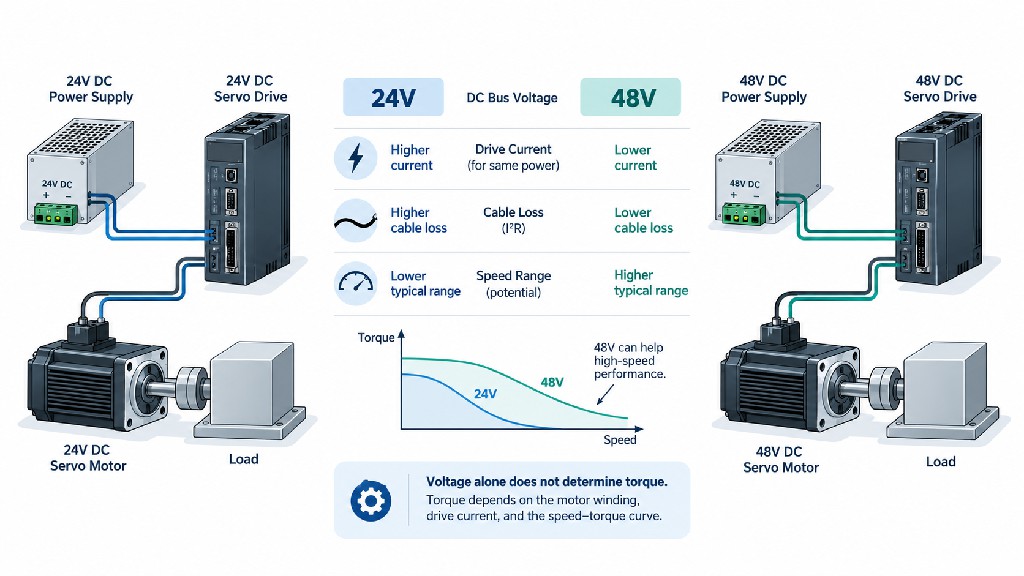
The central rule: A 48V servo motor is not automatically more powerful or stronger than a 24V servo motor. Available torque depends on the motor winding, torque constant, permitted current, thermal limits and motor–drive torque–speed curve. Higher bus voltage can improve the achievable speed range and reduce supply-side current for a given input power, but it does not magically increase a motor's rated torque.
Quick Answer: How to Size a DC Servo Motor
For a first-pass selection, follow this sequence:
-
Define the load and motion: mass or inertia, external force, speed, acceleration, deceleration, running time, stops and operating environment.
-
Convert load motion into shaft speed and torque: include the screw lead, pulley radius, gearbox ratio, friction, gravity and mechanical efficiency.
-
Calculate acceleration torque: add the reflected load inertia and the candidate motor's own rotor inertia.
-
Calculate peak torque and cycle RMS torque: compare peak demand with the allowed peak-torque envelope and RMS demand with the continuous-torque capacity.
-
Check the complete speed–torque envelope: especially when the axis must operate near 3000 rpm or under elevated load at high speed.
-
Choose 24V or 48V and size the drive/power source: check continuous and peak motor current, winding specification, supply operating range, voltage drop and regeneration.
-
Verify encoder, brake, thermal and integration requirements: obtain the motor datasheet, compatible drive list and torque–speed curve before release to production.
A useful preliminary inequality is:
Required RMS torque (with margin) ≤ available continuous system torque at the relevant speeds, and required instantaneous torque ≤ permitted system peak torque for the specified duration.
This is a two-part test. Passing one does not mean that the application passes the other. Oriental Motor's similarly distinguish load torque, acceleration torque, required torque and effective (RMS) torque. Kollmorgen's evaluates the combined effects of speed, torque, inertia and system margins.
What Is a Low-Voltage DC Servo Motor?
A servo is defined mainly by its feedback control system, not by whether the incoming supply is AC or DC. A conventional servo system includes a motor, a position feedback device such as an encoder, a servo drive, and a controller issuing position, velocity or torque commands. The drive monitors feedback and regulates current to achieve the requested response. Many compact DC servo systems use three-phase permanent-magnet brushless motors supplied by an electronic inverter; the word DC usually refers to the drive's low-voltage DC input bus, not to an old-fashioned brushed motor with mechanical commutation.
This distinction is important when specifying DC servo motor selection requirements. A 48V brushless servo should not be connected directly to a 48V supply without an appropriate servo drive. The drive must commutate the motor, read the encoder correctly, enforce current limits and handle faults. Likewise, a BLDC motor with a basic speed controller is not automatically equivalent to a precision servo axis; positioning performance also depends on feedback, control loops and software.
DC servo vs AC servo: the real power-architecture difference
| Design consideration | Low-voltage DC servo system | Typical mains-input AC servo system |
|---|---|---|
| Energy source | 24V or 48V regulated DC supply, battery or shared DC bus | Single- or three-phase AC mains into an AC servo drive |
| Power conversion | DC input → electronic inverter → controlled motor phases | AC input → rectifier/DC link → inverter → controlled motor phases |
| Typical use | Mobile robots, compact machines, battery-powered equipment, low-voltage OEM platforms | Fixed industrial machinery with established AC cabinet power |
| Supply integration | DC voltage range, source current, battery behavior and regeneration are critical | Line voltage, input protection, rectifier/bus, grounding and regeneration are critical |
| Motor technology | Often a brushless permanent-magnet servo motor | Often a brushless permanent-magnet servo motor |
| Safety implication | Lower nominal voltage does not eliminate short-circuit, hot-surface, mechanical or moving-axis hazards | Additional mains-voltage isolation and installation considerations |
| Purchasing implication | Verify the DC drive and source as part of the motor package | Verify AC input rating and drive–motor compatibility as part of the package |
The actual motor electromagnetic design may be closely related in both architectures. The difference is chiefly where the power electronics obtain the DC bus and how the drive/motor combination has been rated. OMRON's describes how the servo drive receives commands and regulates motor power using encoder feedback. Never use the AC/DC label alone to infer accuracy, efficiency or torque superiority.
For FRANK HU MOTOR, low-voltage DC servo selection is particularly relevant because the live presents dedicated 24V and 48V DC models, including 100W, 200W, 400W, 600W, 750W and 1000W configurations. Customers prioritizing compact integration can also review , but integrated steppers and integrated servo products should be evaluated as distinct systems rather than automatically treated as electrically interchangeable.
24V vs 48V Servo Motor: Current, Speed and Drive Capacity
The 24V-versus-48V decision matters enormously to the electrical architecture. It matters less directly to the nameplate torque than many buyers believe. Two correctly designed motors can have the same rated mechanical power, rated speed and rated torque even when one uses a 24V winding and the other a 48V winding.
Why a higher DC voltage can reduce supply current
At a fixed input electrical power, the ideal relationship is:
P_electrical = V_DC × I_DC
A practical estimate that includes motor-and-drive efficiency is:
I_DC,approx = P_mechanical / (V_DC × η_system)
Assume a shaft-output requirement of 400W and 85% combined efficiency for illustration only. The following are estimated average DC source currents during steady operation at 400W shaft output, not manufacturer-rated phase currents:
| Example | 24V system | 48V system |
|---|---|---|
| Mechanical shaft power | 400W | 400W |
| Assumed combined efficiency | 85% | 85% |
| Approximate supply input power | 471W | 471W |
| Approximate DC input current | 19.6A | 9.8A |
| Example round-trip cable resistance | 0.020Ω | 0.020Ω |
Estimated cable heating, I²R |
7.7W | 1.9W |
The electrical loss difference is significant: at approximately half the current, resistive heating through the same cable resistance is roughly one-quarter. That can influence cable gauge, connectors, fusing, supply headroom and control-cabinet temperature. However, actual driver input-current waveforms and RMS cable current vary with PWM operation and the motion cycle. This calculation is not a cable-selection standard or proof that a particular 48V drive is more efficient.
Motor current is not identical to DC bus current
A common specification error is to assume that a motor rated at 10A takes exactly 10A from its 48V supply under every condition. In a three-phase servo drive, motor phase current, DC-link current, RMS current and peak current are different measurements. PWM conversion, operating speed, power factor and regenerative intervals all affect the relationship. Even torque constants may be expressed using RMS or peak current conventions.
Kollmorgen's engineering explanation of explains why current and torque-constant definitions must be consistent. When selecting a driver, ask the supplier whether a current rating means phase RMS, peak phase, continuous DC input or short-term bus current. Do not compare unlike values.
What 48V changes at higher speed
As motor speed increases, back electromotive force (back EMF) increases. The drive needs enough bus voltage to overcome back EMF and winding impedance while still forcing the required current through the motor. If voltage headroom is insufficient, the system may no longer sustain the requested torque at high speed. A suitably paired 48V motor and drive can therefore retain useful speed capability where a 24V combination reaches its voltage limit.
But the key phrase is suitably paired. A 48V version often has different winding turns, torque constant, resistance and inductance from its 24V counterpart. A motor wound for 48V may produce similar rated torque at less phase current. A 24V winding operated from an inappropriate 48V system can exceed its approved speed, current or insulation/thermal limits and is not a valid upgrade path. Always obtain the exact motor–drive torque–speed curve at the intended supply voltage. The distinguishes current-limited continuous/intermittent operation from the voltage-limited boundary of the torque–speed envelope.
When 24V is a sensible choice
Choose a 24V architecture when the machine already has a robust 24V bus, the duty is modest, cable runs are short, space and sourcing favor 24V components, and a verified 24V motor–drive combination achieves the required torque at the required speed. Examples include compact positioning modules, optical inspection mechanisms, light actuators and low-power accessory axes. For a 400W class system, however, current, conductor temperature, connector selection and voltage drop become more demanding than for a 100W system.
When 48V is a sensible choice
Choose a 48V architecture when the machine is battery-based, the bus already supplies other 48V loads, the power level is several hundred watts or more, cable losses matter, or the specified high-speed torque–speed envelope is easier to meet with a qualified 48V winding. This is common for AGV/AMR traction, higher-power robotic joints and compact industrial axes. Confirm the actual permissible supply range: a nominal 48V battery may deliver voltages above or below 48V depending on state of charge and chemistry. The drive's minimum and maximum input limits govern compatibility, not the nominal sticker alone.
A real 24V/48V comparison from FRANK HU MOTOR
The published 100W motor pages list the same 0.32 N·m at 3000 rpm for and . The listed rated motor currents are 6.5A and 3.7A, respectively. Their published torque constants also differ: 0.05 N·m/A for 24V and 0.09 N·m/A for 48V. They have the same listed rated torque, not twice the torque at 48V.
The 200W listings show the same pattern: both 24V and 48V versions specify 0.63 N·m at 3000 rpm, with listed rated currents of 12A and 6A. The 400W pair likewise shows 1.27 N·m at 3000 rpm, with listed rated currents of 20A and 10A. These are product-specific published motor values, not proof of a universal voltage-to-current ratio across all servos. Check all electrical data against the current signed datasheet before specifying a drive, especially if online descriptions have been revised.
Bottom line: Higher voltage may make the overall electrical system easier to design, but torque comes from a matched motor winding and adequate controlled current, within its speed and thermal limits. A 48V label alone never guarantees a stronger motor.
Rated Power and Rated Torque: The Essential Conversion
Servo motor power is mechanical output power at the shaft when used in the rated-performance context. Electrical input power is higher because the motor and drive produce losses. The most useful rotary relationship is:
P(W) = T(N·m) × ω(rad/s)
Since angular velocity is ω = 2π × n(rpm) / 60, the everyday engineering version is:
P(W) = T(N·m) × n(rpm) / 9.5493
Or, rearranged for torque:
T(N·m) = 9.5493 × P(W) / n(rpm)
At a given rated power, a lower rated speed corresponds to a higher rated torque. At a given rated speed, doubling the rated power doubles the calculated rated torque. The equation is a physical relationship, not a promise that torque remains constant at all speeds. At zero shaft speed, mechanical output power is zero even if the servo holds a substantial torque while consuming electrical energy.
What 100W, 200W, 400W, 750W and 1000W mean at 3000 rpm
| Rated shaft power | Calculated rated torque at 3000 rpm | Typical initial shortlist |
|---|---|---|
| 100W | 0.318 N·m | Compact indexing, light positioning and small instruments |
| 200W | 0.637 N·m | Light ball-screw axes, small conveyors and compact automation |
| 400W | 1.273 N·m | Faster linear axes and general-purpose production mechanisms |
| 600W | 1.910 N·m | Midrange robotics, transport and more demanding automation |
| 750W | 2.387 N·m | Higher-load AGV/AMR drives, dynamic industrial mechanisms |
| 1000W | 3.183 N·m | Higher-duty conveying, winding and larger moving axes |
The calculated values align closely with the rounded 0.32, 0.63, 1.27, 1.9, 2.4 and 3.2 N·m values published for FRANK HU MOTOR's corresponding 3000-rpm product families. These figures are rated motor-shaft torques; they are not gearbox output torques, and the application still needs torque margin, a suitable driver and a thermal check.
Example: calculating torque for a 400W DC servo motor
For P = 400W and n = 3000 rpm:
T = 9.5493 × 400 / 3000 = 1.273 N·m
For a requirement of 1.5 N·m continuously at 3000 rpm:
P = 1.5 × 3000 / 9.5493 ≈ 471W
A nominal 400W servo with 1.27 N·m rated torque is not the correct direct-drive continuous-duty choice for this requirement. A 600W-class or larger servo may be worth examining, but only if its actual continuous torque–speed curve, thermal conditions and mechanical interfaces are suitable. A 400W motor's short-term peak rating does not change its continuous rating.
The danger of calculating power at the wrong speed
Suppose an axis needs 2 N·m at 500 rpm, but a buyer calculates power and finds only approximately 105W. It is tempting to order any motor marked 200W. Yet the selected motor still has to produce 2 N·m at 500 rpm. A direct-drive 200W servo from a 3000-rpm family might be rated for only approximately 0.63 N·m continuously. A gearbox, larger motor, low-speed high-torque design or direct-drive solution may be required. Wattage alone does not solve the torque requirement.
Continuous Torque, Peak Torque and RMS Duty
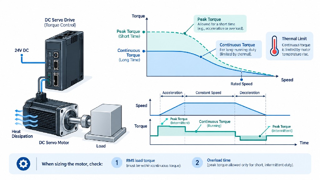
Servo drives can command substantially more torque during short bursts than they can sustain indefinitely. That is useful for rapid acceleration, brief process-force spikes and disturbance recovery. It is dangerous when a designer mistakes peak torque for continuous torque.
-
Rated torque: the manufacturer's continuous torque at the specified rated speed and conditions.
-
Continuous torque envelope: the allowed long-duration torque across speed and cooling conditions; it may not be a perfectly flat line.
-
Peak or intermittent torque: the maximum torque permitted for a limited interval under specified current, temperature and drive conditions.
-
Stall/standstill torque: torque capability at or near zero speed; its permissible duration depends on the rating and cooling.
-
RMS torque: the equivalent thermal torque demand calculated over a complete repeating motion cycle.
The manufacturer must define how long peak torque may be held, how often the peak can repeat and what thermal model the drive uses. The ratings of the motor and drive may impose different constraints: the lower system limit wins. Kollmorgen's explicitly distinguishes rated torque, peak current and standstill capability.
Calculating servo motor acceleration torque
For any rigid rotary element:
T_acc = J_total × α
where J_total is the motor-shaft-referred rotational inertia in kg·m², and α is angular acceleration in rad/s². For a linear ramp in speed:
α = 2π × (n_final − n_initial) / (60 × t_acc)
Motor torque must also overcome load torque:
T_motor ≈ T_process + T_friction + T_gravity + J_total × α
All terms must be expressed at the motor shaft with consistent signs. Gravity may help or resist a movement, and the direction of acceleration changes during deceleration. A simplified calculation should include transmission efficiency and any external force reflected through a pulley, gearhead or screw; more detailed models may include direction-dependent friction and compliance.
RMS torque over a repeating cycle
For piecewise constant torque values:
T_RMS = √[(T1²t1 + T2²t2 + ... + Tn²tn) / (t1 + t2 + ... + tn)]
Here, Ti is the net required motor torque during interval i, and ti is the duration. Negative braking torque still contributes to heating because RMS uses the torque squared. When torque changes continuously, use sufficiently short time intervals or integrate T(t)² over the cycle. Drive and motor thermal models may account for speed-dependent cooling and other losses beyond a simple RMS approximation.
Consider this deliberately simplified two-second cycle for a candidate 400W servo:
| Motion segment | Time | Required motor torque |
|---|---|---|
| Acceleration | 0.20s | +1.80 N·m |
| Constant-speed motion | 0.60s | +0.65 N·m |
| Controlled deceleration | 0.20s | −1.20 N·m |
| Position hold / dwell | 1.00s | +0.07 N·m |
| Total | 2.00s | — |
T_RMS = √[(1.8²×0.2 + 0.65²×0.6 + (−1.2)²×0.2 + 0.07²×1.0) / 2.0]
T_RMS ≈ 0.773 N·m
A 400W FRANK HU MOTOR model with a published 1.27 N·m rated torque and 3.8 N·m peak torque appears plausible for further evaluation: 0.773 N·m is below 1.27 N·m, and the maximum calculated 1.8 N·m is below the listed 3.8 N·m peak. But this is not enough to approve a product. The engineer must verify its continuous and peak envelopes at the actual operating speeds, permissible peak duration, startup temperature, cooling, driver-current limits and any other motion in the cycle. Apply appropriate engineering margin rather than assuming all ratings are exact operating limits.
How much safety margin is appropriate?
There is no single percentage appropriate for every servo axis. Early screening sometimes uses approximately 10–30% additional headroom, but that is a design assumption—not a manufacturer guarantee or universally applicable safety factor. High shock loading, uncertain friction, long cable runs, elevated ambient temperatures, unbalanced vertical axes and machine-safety consequences justify more specific engineering margins. Oversizing also has a cost: larger motors can add rotor inertia, mechanical mass, higher current demand and harder tuning. Choose margin from measured uncertainty and application risk, then validate it with real operation.
How to Calculate Load Torque for Common Machines
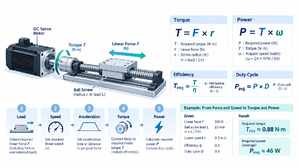
The load creates torque through the mechanical transmission. Start with force, speed and acceleration at the load, then convert them to the motor shaft. Failing to include transmission efficiency is a frequent reason for undersized systems.
Ball-screw-driven linear axis
For a screw lead L in meters per revolution, axial force F in newtons and mechanical efficiency η:
T_screw = F × L / (2π × η)
For a direct-coupled screw:
n_motor(rpm) = 60 × v(m/s) / L(m/rev)
For a horizontal axis, estimate the required axial force as F = m × a + F_process + F_friction, making sure friction is not counted twice if efficiency already represents the relevant losses. For a vertical axis, add or subtract m × g as appropriate for the direction of motion and consider how the load behaves when power is removed. Rotational inertia of the screw, coupling and motor must be added separately to the motor-shaft acceleration calculation. Oriental Motor's gives corresponding load-torque approaches for ball screws, belts and pulleys.
Worked example: A horizontal axis moves 15kg at 4m/s², experiences an additional 100N process force and uses a 10mm/rev ball screw with 90% assumed mechanical efficiency.
-
Force demand:
F = 15×4 + 100 = 160N(friction not separately modeled). -
Screw torque for the linear force:
T = 160×0.010/(2π×0.90) ≈ 0.283 N·m. -
At
v = 0.50m/s, motor speed:n = 60×0.50/0.010 = 3000 rpm. -
The screw's own inertia and the motor rotor's acceleration torque must still be added.
Using a candidate 200W motor rotor inertia of 2.9×10⁻⁵ kg·m², angular acceleration is 2π×4/0.010 ≈ 2513 rad/s²; the motor rotor alone requires about 0.073 N·m. If the screw-plus-coupling inertia were an assumed 1.0×10⁻⁵ kg·m², that adds approximately 0.025 N·m. Preliminary total acceleration demand is roughly 0.381 N·m, before any extra bearing friction or margin. This fits under the listed 0.63 N·m rated torque, but at 3000 rpm the actual torque–speed curve and full-cycle RMS calculation remain decisive.
Pulley, belt or wheel drive
At a pulley or wheel radius r:
T_output = F_tangential × r
ω_output = v / r
n_output = 60 × v / (2π × r)
Include translating mass acceleration, rolling or sliding resistance, belt pretension effects, gearbox friction and wheel-rotation inertia. On an AGV or AMR, do not calculate all drive wheels as if each carries the total tractive load. Distribute the vehicle force according to the actual drivetrain, while checking uneven traction, gradient, payload shift and slip. A nominally powerful servo cannot create usable wheel force beyond the tire–floor traction limit.
Rotary indexing table, drum or articulated joint
A rotary mechanism may have little translational load but substantial rotational inertia. Estimate J_load from the actual shape and mass distribution, including tooling and changing payload. For a simple solid cylinder rotating about its central axis, J = 0.5mr²; for a thin ring, J = mr². CAD mass-property calculations are preferable for complex robotics or indexing tables. Add continuous process torque, seal drag, gearbox drag and any gravity-related joint torque.
The mechanical geometry of a robot arm is especially important. The required torque at a joint changes with arm angle, tool mass and gravity moment. Calculate the worst pose, not only a favorable horizontal-axis demonstration. Repeat the calculation for maximum payload and fast return motion.
Servo Motor Inertia Matching: Why Rotor Size Matters
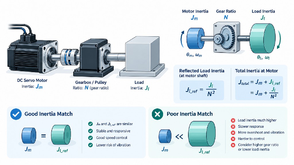
Inertia is a body's resistance to changing rotational speed. A servo motor with ample steady-running torque may still respond poorly when connected to a heavy, high-inertia load through flexible mechanics. Servo motor inertia matching is therefore part of both mechanical design and control tuning.
Let:
-
J_m= motor rotor inertia; -
J_L= load inertia referred to the motor shaft; -
R = J_L / J_m= load-to-motor inertia ratio.
A smaller ratio generally eases high-bandwidth tuning, but the acceptable value depends on mechanical rigidity, drive tuning, disturbance forces and cycle time. There is no universal 10:1 pass/fail rule. As one example, Kollmorgen's discusses keeping reflected inertia within a multiple of motor inertia in its example procedure; other systems tolerate substantially different ratios. Use the intended drive maker's guidance and test the real mechanics.
Reflecting inertia through a gearbox
For an ideal speed reducer with motor speed N times output speed:
J_reflected = J_load / N²
So a 5:1 reducer decreases ideal motor-shaft-referred load inertia to one twenty-fifth. Real designs also have gear and coupling inertia, friction, backlash and torsional stiffness. Reflected load torque changes with ratio and efficiency:
T_motor ≈ T_output / (N × η_gear)
Motor speed increases:
n_motor = N × n_output
A gearbox can reduce the torque and reflected inertia seen by a motor, but may increase the required motor speed enough to violate its torque–speed envelope. Furthermore, encoder resolution at the motor does not eliminate load-side gear backlash.
Worked inertia-matching example
Suppose a rotating load has J_load = 4.0×10⁻⁴ kg·m² and the proposed FRANK HU MOTOR 400W motor has a published J_m = 0.53×10⁻⁴ kg·m² = 5.3×10⁻⁵ kg·m².
| Arrangement | Ideal reflected load inertia | Load-to-motor inertia ratio |
|---|---|---|
| Direct drive | 4.0×10⁻⁴ kg·m² |
7.55:1 |
| 3:1 gearbox | 4.44×10⁻⁵ kg·m² |
0.84:1 |
| 5:1 gearbox | 1.60×10⁻⁵ kg·m² |
0.30:1 |
A gearbox improves the numerical inertia ratio substantially, but its ratio must be chosen after checking output speed, backlash, efficiency, gear inertia and shaft loads. For a fast direct-drive axis, a 7.55:1 ratio could be perfectly workable—or difficult to tune—depending on compliance and the selected drive. Avoid deciding from this single number. Read the more complete for the importance of transmission, load variability and environment.
Include changing payload and motor inertia in the acceleration budget
A robot gripper can move an empty tool, then pick up a heavy part. An AGV may operate with and without cargo. A packaging spool changes diameter and reflected inertia while winding or unwinding. Where inertia changes materially, calculate the extreme cases and a representative production cycle. For every candidate motor, recompute acceleration torque using that motor's rotor inertia; a larger motor is not an inertia-free substitute. Where resonance is possible, specify realistic jerk-limited acceleration, compliant coupling characteristics and drive tuning requirements.
FRANK HU MOTOR: Actual 24V and 48V DC Servo Motor Comparison
The following shortlist uses individual listed product pages rather than invented model families. Every rating shown is a published product figure, with rounded torque values. All listed examples are nominally rated at 3000 rpm and have 17-bit absolute encoder listings. The current column is the motor product's published rated current—not a DC supply sizing recommendation. Product descriptions, rated current conventions, drive compatibility and the complete torque–speed limits must be confirmed with the supplier.
| Product and direct link | DC bus | Rated shaft power | Rated torque | Listed peak torque | Listed rated motor current | Frame |
|---|---|---|---|---|---|---|
| 24V | 100W | 0.32 N·m | 0.64 N·m | 6.5A | 40×40mm | |
| 48V | 100W | 0.32 N·m | 0.64 N·m | 3.7A | 40×40mm | |
| 24V | 200W | 0.63 N·m | 1.9 N·m | 12A | 60×60mm | |
| 48V | 200W | 0.63 N·m | 1.9 N·m | 6.0A | 60×60mm | |
| 24V | 400W | 1.27 N·m | 3.8 N·m | 20A | 60×60mm | |
| 48V | 400W | 1.27 N·m | 3.8 N·m | 10A | 60×60mm | |
| 48V | 750W | 2.4 N·m | 4.8 N·m | 19A | 80×80mm | |
| 48V | 1000W | 3.2 N·m | 6.4 N·m | 25A | 80×80mm |
How to read this table: The similar listed torques for the 24V and 48V 100W/200W/400W pairs demonstrate that supply voltage is not a substitute for a torque rating. The 750W and 1000W rows make 48V attractive for their higher system power, but do not imply that any generic 48V servo drive will work. Peak ratings are conditional on drive current, speed, time and thermal limits. The manufacturer's published data should be reviewed alongside a signed datasheet and actual motor–drive performance curves.
Encoder and brake options beyond the table
The also lists 2500-PPR incremental encoder variants, including a . Several power ratings have suffix YS variants listed with an electromagnetic brake, including 100W, 200W, 400W, 750W and 1000W examples. These are configuration options—not permission to assume that one drive reads every encoder or that a holding brake provides a certified safety function.
Product-data quality note: Some older individual product pages contain mismatches between their narrative copy and their specification tables (particularly encoder wording or nominal voltage). The table above deliberately uses named 17-bit absolute product pages and their published specification fields. Before making a purchase order, request a consistent written specification covering the exact part number, winding, encoder output, brake, rated/peak phase current and compatible drive, plus drawings and a torque–speed curve at the selected DC bus voltage.
Five DC Servo Motor Sizing Examples: 100W to 1000W
The following cases illustrate how to move from an application requirement to an appropriate product shortlist. They are not claims that FRANK HU MOTOR has tested these particular machines. Every example uses explicitly stated assumptions, and the final design still requires the real load-cycle profile, matching servo drive and manufacturer torque–speed curves.
Example 1: 100W, 24V servo for a lightweight inspection-axis belt
Application: A small optical inspection carriage driven by a belt and 15mm-radius pulley. The moving mass is 4kg, the maximum linear speed is 0.8m/s, and acceleration is 1.5m/s². Assume 8N of additional belt/load resistance and a preliminary 90% transmission efficiency.
The pulley output force during acceleration is 4×1.5 + 8 = 14N. Estimated required shaft torque to transmit this force is 14×0.015/0.90 ≈ 0.233 N·m. Allow another 0.04 N·m for the illustrative pulleys, coupling and unmodeled dynamics: approximately 0.273 N·m peak preliminary demand. At 0.8m/s, shaft speed is 60×0.8/(2π×0.015) ≈ 509 rpm.
The has published rated torque of 0.32 N·m and peak torque of 0.64 N·m. This is a reasonable candidate to investigate, because the illustrative acceleration demand is below its rated torque and the operating speed is moderate. To approve the design, calculate RMS torque from the actual imaging cycle and check the 24V drive's torque capability, torque ripple, holding requirements and mechanical accuracy. A 48V version would not automatically improve positioning quality; it may simply align better with an existing 48V cabinet bus.
Buying recommendation: Request the 40mm frame drawing, 24V drive model, feedback pinout, applicable continuous-torque curve and any required cable assembly. If the carriage must remain locked after power loss, evaluate a separately specified brake or mechanical stop rather than relying on servo holding current.
Example 2: 200W, 48V servo for a compact ball-screw automation slide
Application: A 15kg horizontal slide with a 10mm-lead ball screw, 0.5m/s target speed, 4m/s² acceleration, 100N process force and 90% assumed transmission efficiency. The detailed calculation above gives approximately 0.381 N·m acceleration torque when the illustrative screw and rotor inertias are included. The operating speed reaches 3000 rpm.
The lists 0.63 N·m rated, 1.9 N·m peak, and a 48V winding. On torque alone it appears promising. However, reaching the motor's published rated speed makes the continuous and intermittent torque–speed lines especially important. The engineer must also verify whether a high-acceleration motion at the full 0.5m/s speed can be completed with the available travel, and account for screw critical speed, bearing life, nut load and coupling balance.
Why 48V? The 48V winding has a listed 6.0A motor rated current compared with the 24V counterpart's listed 12A. If the machine already uses 48V, the lower motor current specification may simplify matched drive and wiring selection. It still does not establish the required DC input current without the drive data.
Buying recommendation: Request a 48V servo drive and compatible 17-bit absolute encoder interface as one validated combination. If using an external third-party drive, obtain the exact encoder protocol and commutation parameters before ordering the motor.
Example 3: 400W, 24V or 48V servo for a faster CNC auxiliary axis
Application: A 30kg horizontal axis with a 20mm-lead ball screw, a maximum linear speed of 0.8m/s, acceleration of 5m/s², a 150N external process force and 90% assumed screw efficiency. At peak acceleration the linear force is 30×5 + 150 = 300N. Required force-transmission torque is:
T_force = 300×0.020/(2π×0.90) ≈ 1.061 N·m.
At this acceleration, shaft angular acceleration is 2π×5/0.020 ≈ 1571 rad/s². With a candidate 400W rotor inertia of 5.3×10⁻⁵ kg·m² and an assumed screw/coupling inertia of 2.5×10⁻⁵ kg·m², the additional rotational acceleration torque is approximately 1571×(5.3+2.5)×10⁻⁵ ≈ 0.123 N·m.
Total preliminary acceleration demand is about 1.18 N·m, before additional friction and engineering margin. Motor speed at 0.8m/s is 60×0.8/0.020 = 2400 rpm. The and both list 1.27 N·m rated and 3.8 N·m peak torque.
Both deserve consideration, but 1.18 N·m against 1.27 N·m rated leaves only a small instantaneous margin if the process load is sustained through acceleration. Fortunately, acceleration may occupy only a small part of the cycle. Compute actual RMS torque and measure process-force variation before deciding. If the expected continuous load or thermal risk is high, evaluate the for the next power class. At this power level, a 48V bus may be more convenient because the listed rated motor current is 10A rather than the 24V product's 20A, subject to matched-driver verification.
Buying recommendation: Include the acceleration versus distance plot, minimum supply voltage, real cutting or dispensing force and maximum screw speed in the RFQ. Do not order a 400W motor simply because the average mechanical wattage is below 400W.
Example 4: 750W, 48V servo for a geared AGV drive wheel
Application: One powered wheel on an AGV requires an estimated 12 N·m continuous output torque during a demanding operating segment and 30 N·m short-term peak output torque, while turning at 250 rpm. Assume an 8:1 reduction gearbox and 90% gearbox efficiency. The motor would turn at 250×8 = 2000 rpm.
Required motor torques, ignoring additional acceleration of the gearbox/wheel inertia, are:
-
Continuous:
12/(8×0.90) ≈ 1.67 N·m. -
Short-term peak:
30/(8×0.90) ≈ 4.17 N·m.
The lists 2.4 N·m rated and 4.8 N·m peak torque. The example's running demand is below 2.4 N·m, while 4.17 N·m is below 4.8 N·m—yet the peak margin is modest and the omitted inertia could consume it. Check the full drive/motor curve at 2000 rpm, allowable peak duration, wheel slip and battery sag at low state of charge. If frequent peaks occur or rough flooring increases loading, revisit the gear ratio or move to a larger validated system.
Why not choose only by torque? Continuous output power at 12 N·m and 250 rpm is approximately 314W at the wheel; the motor supplies more because of gearbox losses. The 750W nameplate provides a potentially useful envelope for transients and duty, but does not eliminate traction or thermal constraints. On mobile equipment, connector robustness, battery undervoltage behavior, electromagnetic compatibility and environmental sealing are often as important as peak torque.
Buying recommendation: Quote the motor, gearbox, encoder, drive, brake if needed, cables and operating battery-voltage range together. Establish how safe stopping and parking are achieved; a motor holding brake is not automatically a certified vehicle parking system.
Example 5: 1000W, 48V servo for a demanding production drum
Application: A production indexing drum operates at 2400 rpm during its running phase, requiring about 2.5 N·m of shaft torque, and briefly needs 5.0 N·m to accelerate or recover from process disturbances. Mechanical output power at the constant-speed point is 2.5×2400/9.5493 ≈ 628W. Consider the following illustrative ten-second thermal cycle:
| Segment | Torque | Duration |
|---|---|---|
| Running | +2.5 N·m | 6.0s |
| Short acceleration peak | +5.0 N·m | 0.5s |
| Deceleration | −2.0 N·m | 0.5s |
| Light dwell/holding | +0.2 N·m | 3.0s |
T_RMS = √[(2.5²×6 + 5.0²×0.5 + 2.0²×0.5 + 0.2²×3)/10] ≈ 2.28 N·m.
The lists 3.2 N·m rated torque, 6.4 N·m peak torque and 25A rated motor current. These headline figures make it a candidate for a more detailed design review. Because the shaft is running at 2400 rpm and intermittent demand reaches 5.0 N·m, the permitted torque–speed envelope at the target voltage and the drive peak-current time limit are critical. A 1000W motor does not mean that 1000W is continuously available under every ambient-temperature or enclosure condition.
Buying recommendation: Request the system's complete thermal and regenerative-braking ratings, cycle-time validation, maximum drive input current and any additional brake-resistor or active-energy-management requirements. Consider a gearbox or different motor geometry if the drum's load inertia is too large for the required response.
Incremental vs Absolute Encoder: Choose the Feedback Interface Before Ordering
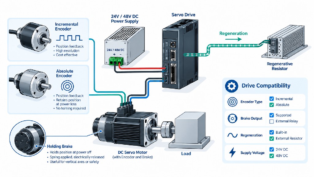
An encoder reports motor rotation to the drive. It affects commutation, position and speed estimation, homing behavior and error diagnosis. An encoder is not merely an optional resolution upgrade; in many servo designs, encoder compatibility determines whether a motor can run with a chosen drive at all.
Incremental encoder
An incremental encoder produces changes in position, commonly through quadrature A/B signals and an index or Z signal. For an encoder specified at 2500 pulses per revolution (PPR), a quadrature decoder using all four A/B edges can obtain 10,000 counts per motor revolution, provided the encoder and receiver use the stated conventions. That gives a theoretical angular count increment of 360°/10,000 = 0.036° at the motor. Count resolution is not the same as accuracy, and the drive also needs an appropriate strategy for electrical rotor-angle commutation.
Incremental systems frequently need a reference or homing sequence after loss of position information. They may suit controlled equipment where homing is practical and the drive explicitly supports the encoder's signal type and electrical levels.
Absolute encoder
An absolute encoder reports a position code rather than depending solely on counted changes since startup. A 17-bit single-turn position code represents 2¹⁷ = 131,072 nominal positions per turn, equivalent to approximately 0.00275° per count. This is feedback resolution, not guaranteed motor-shaft accuracy. Multi-turn capability adds information about the number of revolutions, if supported by the exact encoder and retention arrangement.
Absolute feedback can reduce or eliminate the need for homing in some systems, but it does not guarantee power-loss position retention under every configuration. Some multi-turn encoders use batteries; others use mechanical or energy-harvesting methods. Verify the claimed single-turn/multi-turn functionality, drive communication protocol, backup needs, power-loss behavior and commissioning procedure. OMRON explains the underlying and the practical consequences for servo initialization in its .
| Selection issue | 2500-PPR incremental option | 17-bit absolute option |
|---|---|---|
| Basic information | Change in angle, with counting | Encoded angular position |
| Example nominal counts | Up to 10,000/rev with x4 quadrature | 131,072/rev for 17-bit single-turn position |
| Restart behavior | Often requires position reference/homing | May retain usable position; depends on single/multi-turn implementation |
| Cable and signaling | Check differential/single-ended A/B/Z levels | Check exact proprietary or standard serial protocol |
| Integration cost | May be attractive with existing incremental hardware | Can simplify startup on supported systems |
| Essential question | Can the driver commutate and count this encoder? | Does the driver speak the encoder protocol and support retention? |
A motor's high encoder count does not remove mechanical backlash, screw pitch error, elastic deflection or bearing runout. In critical axes, a load-side linear scale or external encoder may be required. For a matched solution, ask FRANK HU MOTOR to provide the specific encoder model, pinout, protocol and compatible-drive parameter file for the exact motor order code, not only the phrase “17-bit absolute encoder.”
Drive Compatibility and Power Supply Sizing
The motor and drive are a matched control and power pair. Verify voltage first, then current and feedback, but do not stop there. The driver must know the motor's pole configuration, electrical constants and encoder alignment. An apparently compatible PWM inverter may not be a compatible high-performance servo drive.
Minimum drive compatibility checklist
-
DC input range: normal source voltage, minimum voltage under acceleration, battery full-charge voltage and maximum tolerated regenerative voltage.
-
Motor continuous output current: match the manufacturer's defined phase-current basis (RMS versus peak) to the continuous torque requirement.
-
Motor peak current and duration: verify peak torque at the speed and duration actually required.
-
Encoder compatibility: correct feedback protocol, voltage, connector, pinout, resolution and commutation/alignment procedure.
-
Control interface: pulse/direction, analog, CANopen, RS485, EtherCAT or other required interface—only if supported by the actual drive model.
-
Safety and protective behavior: overcurrent, overtemperature, overvoltage, undervoltage, overspeed, following error, enable/STO where required, emergency-stop integration and loss-of-feedback behavior.
-
Regenerative capability: internal capacitance, overvoltage thresholds, bus-sharing options, resistor or energy sink, if applicable.
-
Firmware and tuning: exact motor profile, current-loop configuration, filters and commissioning documentation.
Do not assume that the FRANK HU MOTOR OK2D872 stepper driver or any generic BLDC speed controller is suitable for these DC servo products. Driver ratings such as “48V, 20A” are insufficient without the intended motor family, feedback and current conventions. Ask for an explicitly servo-compatible drive recommendation.
Sizing the power supply
For a first budget, estimate average input power from mechanical work and approximate efficiency, then separately evaluate short-term supply current, bus capacitance, simultaneous axes, voltage sag and regeneration. The source must tolerate the real dynamics of the motor drive, not merely the wattage on the motor label.
At an assumed 85% combined efficiency and full rated mechanical power:
| Illustrative shaft output | Approximate DC input power | Estimated DC current at 24V | Estimated DC current at 48V |
|---|---|---|---|
| 100W | 118W | 4.9A | 2.5A |
| 200W | 235W | 9.8A | 4.9A |
| 400W | 471W | 19.6A | 9.8A |
| 750W | 882W | 36.8A | 18.4A |
| 1000W | 1176W | 49.0A | 24.5A |
These are calculated DC-bus examples, not actual catalog motor/driver ratings or evidence of 24V 750W/1000W products. The actual instantaneous current and losses depend on the motor, inverter, motion cycle and voltage. Also, continuous mechanical output at rated speed is not the same as a fast acceleration event. Multiple axes can demand high current simultaneously. Size fuses, protection, wires, connectors and power supplies using actual continuous/RMS and peak requirements and the applicable electrical standards.
Supply-voltage sag and multi-axis systems
An undersized DC source may drop below the driver's undervoltage threshold precisely when the machine demands acceleration. Long thin cables can worsen that problem. Battery-powered robots also need a verified operating range over temperature, charge and aging. For several axes sharing one bus, consider whether their peak loads coincide. One axis decelerating may briefly support another accelerating if the drive/bus is designed to share energy, but this cannot be assumed without compatible electrical protection and regeneration management.
Regenerative Braking: What Happens When the Load Decelerates?
A servo axis can become a generator. During rapid deceleration or descent of an overhauling vertical load, mechanical energy may return to the DC bus. If the supply cannot accept that energy and the drive has no proper dissipation path, bus voltage can rise above the safe limit and trigger an overvoltage fault. A conventional one-way switched-mode DC supply should not be assumed capable of sinking reverse current.
A useful first approximation for rotational kinetic energy is:
E_kinetic = 0.5 × J_total × ω²
Energy removed when slowing from ω1 to ω2 is:
ΔE = 0.5 × J_total × (ω1² − ω2²)
For example, if J_total = 0.001 kg·m² and speed falls from 3000rpm to zero, the change in rotational energy is approximately:
ΔE = 0.5×0.001×(314.16²) ≈ 49.3J.
This does not mean that exactly 49.3J will enter a braking resistor. Some energy is consumed in load friction, motor/drive losses or other machinery; gravitational or externally driven loads may add energy. Check both the energy per stopping event and average regenerated power over repeated cycles, along with the bus capacitance and allowed voltage window.
Potential strategies include a drive with an appropriately specified braking resistor, an energy-sinking/regenerative DC supply, a shared DC bus designed for energy transfer, or an engineered battery/bidirectional converter arrangement. Follow the specific drive manufacturer's resistor resistance, peak power, average power and wiring requirements. Do not connect an arbitrary resistor across a 48V bus. Kollmorgen's explains the bus-overvoltage mechanism and selection of compatible resistor hardware.
Important distinction: Electrical/regenerative braking dissipates or redirects kinetic energy while the motor is rotating. It does not mechanically secure a suspended load at zero speed after loss of power.
Does Your Servo Motor Need an Electromagnetic Holding Brake?
A servo can actively hold position while energized, but its motor torque disappears as a controllable holding force if the drive is disabled or loses power. Consider a spring-applied, electrically released holding brake, mechanical lock or counterbalance when an axis must remain stationary after shutdown. Examples include vertical ball-screw axes, elevated grippers, lifting devices and some robotic joints.
Brake selection requires its own calculations:
-
Static holding torque at the actual motor or gearbox shaft: include load weight, transmission efficiency, orientation and margin.
-
Brake location: a motor brake acts through couplings and gearing; failure of a downstream connection can still release the load.
-
Engage/release timing: coordinate with servo enable so the brake does not drag while driving and the load does not fall before the brake engages.
-
Coil supply: check 24V or other specified brake-coil voltage and current independently of the servo's 24V/48V winding.
-
Cycle and wear rating: a holding brake may not be designed for repeated high-energy dynamic stops.
-
Functional safety: a generic motor brake is not automatically safety-rated. Human-safety functions require a risk assessment and suitable validated measures.
The FRANK HU MOTOR product catalog includes electromagnetic-brake versions of several DC servo families, but the presence of a “YS” brake option does not document the required holding torque, life, response time or functional-safety category for your application. Request the brake's actual datasheet, including holding torque, voltage, release and engagement times, permissible wear and safe-use limitations. Rockwell Automation's distinguishes dynamic braking from a positive-action mechanical holding brake. Braking and axis-safety design should be checked by qualified machine engineers.
Temperature, IP Rating and Mechanical Fit Are Selection Criteria Too
Even a perfectly calculated torque profile can fail in service because of temperature, enclosure design or mounting geometry. Verify ambient temperature, altitude if relevant, duty cycle, enclosure ventilation and heat transfer through the motor mounting flange. Servo continuous torque depends on the conditions used for its rating. A sealed motor on an insulated bracket may behave differently from the same motor bolted to a large metal machine frame.
Many FRANK HU MOTOR DC servo listings specify IP65, but IP ratings apply only under the product's specified installation conditions. Confirm shaft-seal and connector coverage, cable-gland assembly and whether the rating applies to the motor body alone. IP65 does not automatically mean submersible, washdown-chemical-resistant or suitable for every food-processing environment.
Frame sizes such as 40×40mm, 60×60mm and 80×80mm identify mounting-envelope families, not guaranteed shaft or bolt-pattern interchangeability. Review the complete drawing: flange pilot, hole circle, shaft diameter, keyway, shaft length, axial/radial load capacity, cable exit and total length including any brake. A replacement servo must also match feedback and motor electrical parameters even if it bolts into the same opening. Kollmorgen's highlights environmental operating conditions as part of correct system selection.
DC Servo Motor Sizing Worksheet — Copy Into Your RFQ
To obtain a reliable motor-and-drive recommendation, fill in the following worksheet and send it with any motion profile, CAD drawing or gearbox information. Unknown values can be marked TBD rather than guessed. FRANK HU MOTOR can then help compare the relevant and associated components.
| Field | Your value | Example / explanation |
|---|---|---|
| Company, project and end use | __ | OEM robot, CNC machine, inspection stage |
| Quantity (prototype / annual) | __ | 2 prototypes / 300 units annually |
| Axis type | __ | Belt, ball screw, rotary, wheel, joint |
| Axis orientation | __ | Horizontal / vertical / inclined |
| Moving load mass | __ kg | Include maximum payload |
| Load moment of inertia | __ kg·m² | State location and axis |
| Pulley effective radius | __ mm | If applicable |
| Ball screw lead | __ mm/rev | If applicable |
| Gear reduction ratio and efficiency | __ | Motor:output speed ratio |
| External process force / torque | __ N or N·m | Cutting, gripping, tension, rolling |
| Maximum load speed | __ mm/s or rpm | Include operating duration |
| Acceleration / deceleration | __ | m/s², rad/s² or ramp times |
| Travel distance / cycle | __ | Specify stroke and duty |
| Running, acceleration, deceleration, dwell times | __ | A complete repeating motion profile |
| Calculated motor peak torque | __ N·m | Include reflected inertia |
| Calculated motor RMS torque | __ N·m | Complete cycle |
| Calculated maximum motor speed | __ rpm | After gearing |
| Rotor/load inertia ratio | __ | Once motor is shortlisted |
| Available DC bus | 24V / 48V / other | Include min/max input range |
| Regulated supply or battery | __ | Include source/sink limits |
| Required controller interface | __ | Pulse/direction, CANopen, etc. |
| Encoder preference | Incremental / absolute / TBD | Include protocol, retention needs |
| Homing after power loss acceptable? | Yes / No / TBD | Check absolute feedback requirements |
| Holding brake required? | Yes / No / TBD | Include static torque and risk |
| Required accuracy and repeatability | __ | Specify at the load, not just motor |
| Ambient temperature, contaminants and IP | __ | Include enclosure/mounting |
| Mechanical dimensions and shaft details | __ | Attach drawing/3D model |
| Desired sample lead time | __ | Request confirmed quotation |
| Certification/documentation needs | __ | Applicable product-specific records |
Worked RFQ summary in one paragraph
“We need a low-voltage servo for a 30kg horizontal ball-screw axis. Lead is 20mm/rev, maximum linear velocity is 0.8m/s, acceleration is 5m/s², external process force is 150N, and assumed screw efficiency is 90%. Preliminary motor speed is 2400rpm and acceleration torque is 1.18 N·m before final margin. Our machine has a 48VDC power bus. Please propose a compatible motor and drive, confirm continuous/peak torque at 2400rpm, provide encoder protocol, phase-current conventions, inertia, wiring, CAD drawing and regeneration requirements, and quote sample plus annual quantities.”
This request is far more effective than asking for “one 400W motor with encoder.” It allows supplier engineers to evaluate the complete operating envelope, and it helps procurement compare quotations consistently.
Procurement Checklist: Compare Total Servo-System Cost
Motor price is only one line in a production bill of materials. A cheaper motor with incompatible feedback or unavailable spare cables can become the more expensive choice after engineering rework or downtime. Ask every supplier to quote the whole functioning axis, including the motor, encoder, servo drive, required power supply, brake, cables, connectors, gearbox, mounting accessories and documentation.
| Purchase criterion | What to verify before releasing an order |
|---|---|
| Mechanical capability | Rated and peak torque–speed curves for the exact motor/drive/bus combination |
| Electrical compatibility | Rated and peak currents with measurement conventions; bus input operating range |
| Feedback | Exact encoder protocol, resolution, wiring, compatibility and retention |
| Inertia | Motor rotor inertia and reflected load inertia with actual gearing |
| Thermal duty | Continuous and intermittent ratings under expected ambient conditions |
| Braking | Regeneration path, maximum bus voltage and any holding-brake performance |
| Mechanical interface | Dimensions, flange, pilot, shaft, loads, seals, gearbox backlash |
| Control integration | Interface, parameter file, alarm handling, tuning tools |
| Reliability | Duty-cycle testing, fault behavior, spare-part availability |
| OEM support | Samples, customization, batch consistency, change notification |
| Compliance | Product-specific CE/RoHS documentation where applicable; applicable machine standards |
| Commercial terms | Unit and system price, MOQ, sample lead time, delivery and warranty |
FRANK HU MOTOR offers a range of motors, drives and customization options for machine builders. Buyers seeking a compact solution may investigate the ; those considering an economical alternative for slower axes can compare closed-loop stepper choices using the . No category change should be approved without a fresh torque/speed and thermal calculation.
Common DC Servo Motor Selection Mistakes
Mistake 1: “48V has twice the torque of 24V.” Wrong. Compare rated torque, winding torque constant, drive current and speed–torque envelope. The published FRANK HU MOTOR 100W and 400W 24V/48V pairs list the same rated torque within each power class.
Mistake 2: Choosing a 400W servo only because the calculated average power is 350W. Average power cannot replace peak acceleration torque, low-speed continuous torque or a cycle RMS check.
Mistake 3: Treating peak torque as continuous torque. A listed 3.8 N·m peak may last only a permitted short interval. The motor's continuous capability and the drive's thermal model determine safe duty.
Mistake 4: Ignoring motor and gearbox inertia. A larger motor increases its own rotor inertia; an inappropriate gear ratio can put the motor beyond its useful speed or introduce unacceptable backlash.
Mistake 5: Comparing drive DC input current with motor phase current. Specify measurement conventions, and check the actual matched drive limits. A printed “20A” is not enough information.
Mistake 6: Assuming an absolute encoder works with any servo driver. A 17-bit label says little about electrical signaling, protocol, commutation setup or power-loss multi-turn behavior.
Mistake 7: Using a generic supply that cannot deal with regeneration. Fast stopping or lowering a load can raise the DC bus voltage and trip the drive.
Mistake 8: Believing an energized servo or a generic holding brake is a complete safety system. Design safe vertical-axis holding, stopping and fault responses based on a real risk assessment.
Mistake 9: Selecting from the catalog without checking the current drawing. Similar frame dimensions can hide different shaft and connector interfaces, and some old online descriptions may disagree with tabulated specifications.
Mistake 10: Oversizing to avoid calculations. A larger, more expensive motor may reduce tuning quality, raise inrush/peak requirements and add moving mass without improving the machine's actual performance.
Frequently Asked Questions About DC Servo Motor Sizing
How do I size a DC servo motor for a CNC machine?
Start with the moving mass, tool or process forces, screw lead or belt/pulley geometry, desired traverse speed and acceleration. Calculate force at the load, convert it to motor-shaft torque and speed, add rotational acceleration torque, and calculate peak and RMS torque over the actual cycle. Select a motor–drive pair whose speed–torque curve covers all required points. Include screw critical speed, machine stiffness, repeatability and regenerative stopping. A CNC axis with a heavy screw may have substantially more inertia than its moving mass suggests.
Is a 48V DC servo motor more powerful than a 24V servo motor?
Not necessarily. The voltage rating is part of the electrical operating architecture. For the same power, 48V generally permits a lower source-side current, and a matched 48V motor–drive design may provide useful voltage headroom at speed. But torque is not proportional to bus voltage. FRANK HU MOTOR lists 100W 24V and 48V motors at the same rated 0.32 N·m, and 400W versions at the same rated 1.27 N·m. Compare the exact windings, currents, speed and thermal limits.
What is the difference between a 400W and a 750W DC servo motor?
At 3000 rpm, 400W corresponds to approximately 1.27 N·m rated torque, while 750W corresponds to about 2.39 N·m. FRANK HU MOTOR lists approximately 1.27 and 2.4 N·m, respectively, for relevant products. The 750W motor typically also has different rotor inertia, frame dimensions and current requirements. Bigger is not always better; use the duty cycle, speed–torque envelope and inertia-matching calculation to choose.
Can I operate a 24V servo motor from a 48V drive?
Not without explicit manufacturer approval for that exact motor, winding, firmware and current/speed configuration. A drive with a programmable current limit is not automatically sufficient, since voltage, back EMF, insulation, overspeed and protection behavior all matter. Select a manufacturer-approved motor–drive pairing and observe its documented input and motor ratings.
How do I calculate servo motor torque from power and RPM?
Use T(N·m) = 9.5493 × P(W) / n(rpm). For 400W at 3000rpm, torque is about 1.273 N·m. For 750W at 3000rpm, it is about 2.387 N·m. This is the mechanical power–speed relationship at the operating point; it does not replace the manufacturer's continuous/peak torque–speed curve.
What inertia ratio is acceptable for a servo motor?
There is no universal maximum. Lower reflected load-to-motor inertia ratios generally simplify fast response, but some rigid, well-tuned systems operate at high ratios. Calculate actual reflected inertia using gearbox ratio squared, include gearbox/coupling inertia, check mechanical resonance and follow the selected drive manufacturer's tuning recommendations. Do not select a motor based only on an arbitrary 10:1 threshold.
Is a 17-bit absolute encoder better than a 2500-PPR incremental encoder?
It depends on the application. A 17-bit absolute encoder offers 131,072 nominal single-turn positions and may simplify restart or homing on supported systems; a 2500-PPR incremental encoder can yield up to 10,000 quadrature counts per revolution with x4 decoding and may suit existing electronics. Neither guarantees comparable absolute accuracy at the load. Verify the encoder protocol, power-loss behavior and compatibility with your servo drive.
Do low-voltage DC servos require a braking resistor?
Some applications do, and some do not. Decelerating inertia can return energy to the DC bus, but the amount depends on load inertia, speed, frequency of stops and losses. The drive may absorb it internally, transfer it elsewhere or require an appropriately sized external braking element. Use the drive maker's regeneration calculation and approved hardware. Never assume a generic DC supply can sink energy.
Should an AGV motor use an electromagnetic brake?
That depends on parking, incline, emergency stopping, risk and drivetrain requirements. An energized servo can control wheel torque, but it should not be assumed to hold a parked vehicle indefinitely after power loss. A motor-mounted holding brake may help, yet wheel-to-ground traction, gearing and brake reliability must all be considered. The overall vehicle design must meet its applicable safety requirements.
Can I buy the motor before selecting the servo drive?
It is safer to select both together. Encoder compatibility, current definitions, motor commutation, voltage headroom, protection and regeneration all depend on the drive. For prototypes, request a validated motor–drive combination, not an isolated motor selected from its price and wattage.
What should I send FRANK HU MOTOR for a sizing recommendation?
Send the completed worksheet above, any mechanical drawings, motion times, force or inertia estimates, 24V/48V source details, required position accuracy and controller interface. If you already have a drive, include its exact model and firmware version. Ask for a proposal with the actual motor and drive part numbers, datasheets, torque–speed curve, encoder information and a quotation for prototype and production quantities.
Final Selection Recommendation
Successful DC servo motor sizing starts with the machine, not with the motor catalog. Determine peak and RMS motor-shaft torque, required speed, reflected inertia and motion duration first. Next, decide whether a 24V or 48V architecture best fits the actual source and driver requirements. Then check encoder, regeneration, holding brake, mechanical fit, cooling and the total installed system cost.
For light precision positioning, begin with a 100W or 200W DC servo shortlist. For faster CNC-related automation and moderate dynamic loads, investigate 400W systems while checking acceleration margins carefully. For higher-load mobile platforms, robots and demanding production mechanisms, evaluate 750W and 1000W 48V DC servo systems against the real speed–torque envelope and duty cycle. These power classes are starting points, not automatic application approvals.
Explore FRANK HU MOTOR's , compare related , or consider the packaging advantages of an . For an engineering-backed quotation, with your DC Servo Motor Sizing Worksheet and ask for a documented motor + drive + encoder + power/braking recommendation matched to your machine.