motor construction, load torque, operating speed, thermal limits, transmission losses, mechanical packaging and the actual duty cycle.
A coreless DC motor, also called an ironless DC motor in many contexts, is attractive because it can offer smooth motion, low rotating inertia and high power density in a compact package. Those advantages are especially valuable in medical devices, analytical instruments, miniature robots, inspection systems, precision tools and battery-powered equipment. But the term coreless does not eliminate engineering trade-offs. A small motor still has limited continuous torque, winding temperature limits, bearing loads, electronic control requirements and, when fitted with gearing, transmission constraints.
This selection guide explains how to specify a coreless motor as part of a complete motion system rather than purchasing by diameter or advertised no-load RPM alone. It compares brushed ironless motors with slotless or ironless brushless designs, gives practical calculation methods and uses published 12 mm, 16 mm and 22 mm examples from the . It also explains which information buyers should submit when requesting an OEM motor, custom shaft, gear ratio or mechanical integration drawing.
Important specification note: The product figures below are published catalog values, not results of independent endurance or thermal tests. Unless a product page explicitly states otherwise, do not interpret a no-load speed, a maximum gearbox torque or a nominal power value as a verified continuous operating guarantee in your finished machine. Confirm the latest drawing, permissible load, operating temperature and duty-cycle rating before design release.
Quick Answer: How Do You Choose a Coreless DC Motor?
Start at the driven output shaft, not at the motor's marketing description. Define the actual speed, continuous torque, peak torque, time spent accelerating, supply voltage and available installation envelope. Then decide whether direct drive is possible or a planetary gearbox is necessary. Convert the load requirements back through the proposed gearbox to the motor shaft, taking efficiency and inertia into account. Finally, check current, winding temperature, output-shaft loading, noise, feedback and lifetime under the intended duty cycle.
For a fast, light load, an ungeared coreless motor or a low-ratio geared version may be appropriate. For a slower actuator that needs more output torque, a small planetary gearmotor is often a better starting point. For continuous duty, repeated reversals or tightly controlled speed, a suitable coreless brushless DC motor with an appropriately matched electronic driver may justify the added control complexity. For a cost-sensitive device with short operating intervals, a brushed ironless motor can still be the best technical and commercial choice.
Do not confuse a low rotational inertia with high torque capacity. Low inertia helps a motor respond quickly; it does not permit unlimited acceleration current, holding torque or thermal loading. Likewise, a 500:1 gearbox does not make a 12 mm mechanism indestructible. The gearhead's published torque rating, efficiency, backlash, wear and allowable shaft loads remain hard constraints.
A practical selection order is: define load → establish space and power → choose commutation type → estimate ratio → verify rated speed and torque → calculate transient current and heating → check feedback, noise and EMC → validate prototypes. This order saves more engineering time than starting with the smallest available diameter.
What Is a Coreless DC Motor?
A conventional iron-core brushed DC motor has armature windings supported by an iron-laminated rotor. That iron contributes to the magnetic circuit and helps shape torque production, but it also adds rotating mass. It can introduce magnetic attraction effects, iron losses and cogging behavior associated with the rotor's geometry. The conventional design is common and economical, but it is not automatically ideal for very small instruments or highly responsive axes.
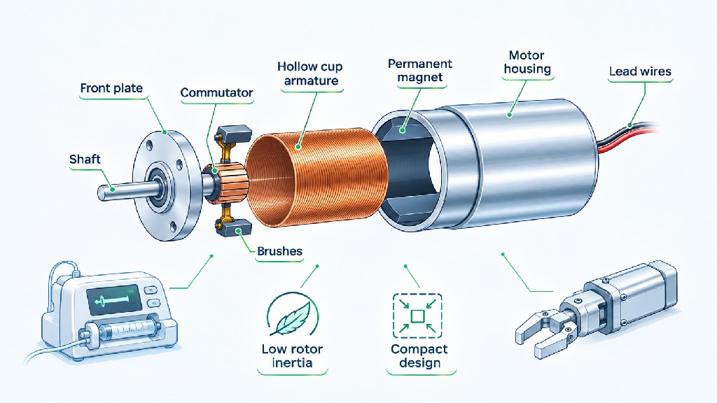
In a typical brushed coreless DC motor, the rotating armature is instead a self-supporting, cup-shaped or cylindrical copper winding without a laminated iron core. Permanent magnets and a stationary magnetic return path provide the magnetic field. The hollow winding rotates around the stationary magnetic structure, while brushes and a commutator supply current to the moving coil. Removing the rotating iron reduces inertia and avoids conventional iron-tooth cogging in the armature. The result is potentially smoother low-speed motion, rapid acceleration and good efficiency in a small volume.
FAULHABER describes its own ironless brushed technology as a self-supporting, skew-wound copper rotor and explains the resulting low inertia and cogging-free behavior in its . This is a useful description of the physical principle, not a claim that every manufacturer's winding arrangement is identical.
The expression ironless must be used carefully. It usually means the winding support or armature lacks a conventional iron core, not that the entire machine contains no ferromagnetic material. Permanent-magnet motors still need a designed magnetic circuit. Similarly, a motor advertised as small diameter is not necessarily coreless, and a motor advertised as brushless is not necessarily slotless or ironless.
A good engineering drawing or cutaway should identify the stationary magnetic structure, the rotating or stationary winding, the magnets, the bearings, the shaft and the commutation method. These details are more useful than a generic image of a cylindrical motor with the word “coreless” attached.
Brushed Coreless vs Coreless Brushless DC Motors
Two different architectures are often sold under closely related names. Understanding the location of the winding is essential, particularly because marketing descriptions sometimes use coreless, ironless and slotless interchangeably.
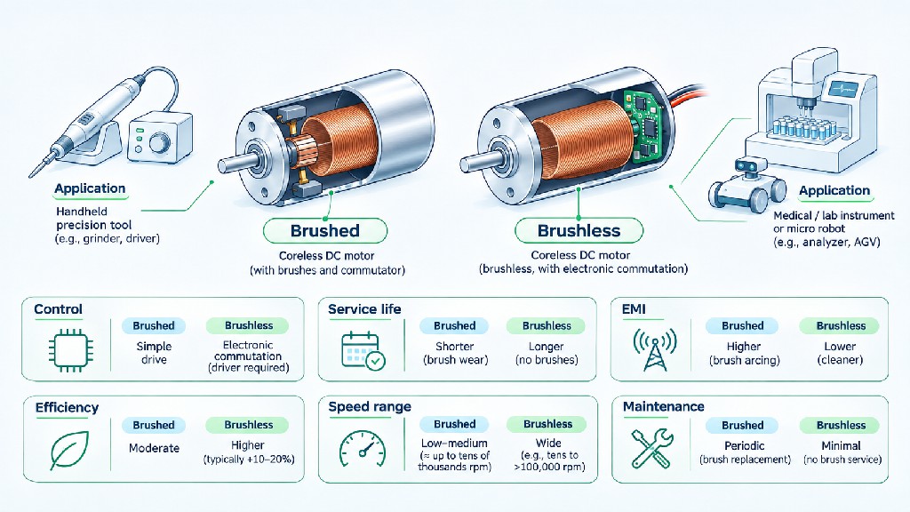
In a brushed ironless motor, the self-supporting copper winding generally rotates. A mechanical brush-and-commutator assembly switches current. In an ironless or slotless BLDC motor, the winding is typically stationary, and the permanent-magnet rotor turns while the electronic driver commutates the phases. In the brushless case, the slotless stator winding helps reduce cogging, but the rotor still contains magnets; therefore, the low inertia of a brushed cup-winding rotor cannot automatically be assumed for every brushless design.
Portescap distinguishes iron-core and coreless brushed motors from slotted and slotless brushless motors in its . This distinction matters when interpreting a specification sheet: the commutation method and magnetic construction are two separate dimensions of motor selection.
| Selection factor | Brushed ironless / coreless DC | Slotless / ironless brushless DC |
|---|---|---|
| Current commutation | Brushes and mechanical commutator | Electronic controller and rotor-position information or estimation |
| Winding location in common designs | Rotating self-supporting winding | Stationary slotless winding |
| Main wear concern | Brushes, commutator and bearings | Bearings, electronics and environmental stresses |
| Controller complexity | Direct DC or suitable PWM/H-bridge is often sufficient | Matched BLDC drive is required |
| Low-speed behavior | Can be smooth with suitable load and control | Smoothness depends strongly on sensing and commutation strategy |
| Typical commercial fit | Short-duty, compact and cost-sensitive equipment | Frequent starts, sustained operation and applications prioritizing brush-free operation |
Brushed motors are not inherently inferior. A compact medical instrument used intermittently may benefit from the simple power electronics and low drag of a carefully specified brushed motor. The brush contact material, speed, current and expected number of cycles should be selected together. Precious-metal and graphite brush systems, for example, are intended for different operating conditions; one should not be substituted for the other solely because it appears more durable.
Brushless versions remove brush-contact wear, but they add a controller, phase wiring and a starting strategy. Hall-based commutation is relatively straightforward and often useful for low-speed startup; sensorless control can be effective in suitable rotating loads but may be unsuitable when starting under high load or requiring deterministic near-zero-speed motion. Higher-performance systems may need an encoder and sinusoidal or field-oriented control. The explains how driver architecture affects a motor's practical behavior.
The correct comparison is therefore not “brushed versus brushless” in isolation. It is the cost, performance, acoustic profile, electronics, reliability and total assembly size of two complete, working drive systems.
Why Low Rotor Inertia Improves Dynamic Response
Every rotating mechanism resists changes in speed. The relevant relationship is:
Acceleration torque = rotational inertia × angular acceleration, or T = J × α.
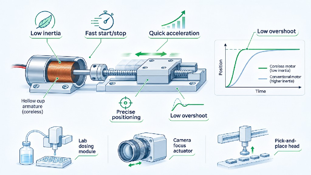
Here, T is torque in newton-metres, J is rotational inertia in kg·m² and α is angular acceleration in rad/s². If the required acceleration is unchanged, a lower combined inertia reduces the torque needed to accelerate the rotating components. If the available acceleration torque is unchanged, reducing inertia allows a faster change in speed. That is one reason a coreless motor can respond quickly in a precision dispenser or inspection mechanism.
Consider two hypothetical, otherwise comparable rotors. Rotor A has an inertia of 1.0 × 10⁻⁷ kg·m²; rotor B has 3.0 × 10⁻⁷ kg·m². To accelerate either one at 2,000 rad/s², A requires 0.0002 N·m and B requires 0.0006 N·m just for rotor acceleration. These numbers are illustrative calculations, not measured values for any FRANK HU MOTOR model. They exclude load inertia, friction, gears and other losses.
The difference may seem tiny, but miniature motors often work with torque measured in millinewton-metres. An additional fraction of a millinewton-metre can materially affect peak current, settling time and control margin. Rapidly repeating the motion may also create a significant thermal load even when each individual movement is short.
There is an important limitation: low inertia at the motor does not guarantee low inertia for the complete mechanism. The system also accelerates the gearhead, shaft, couplings and reflected load. If the driven load is large relative to the motor, rotor-inertia savings can become a small part of the total. Furthermore, a high-ratio gearhead can add its own rotating inertia, friction, torsional compliance and backlash.
Acceleration is also bounded by the motor's permitted peak current and the driver's current limit. A motor with an extremely responsive rotor can still overheat when it repeatedly generates large acceleration torque. For short-cycle automation, calculate the entire torque-versus-time sequence and verify that both the maximum transient load and the effective heating remain acceptable.
Specify the Load Before Choosing a Diameter
The most useful motor requirement is a load profile, not a request for “a powerful 16 mm motor.” Define what the output must do while carrying the real load. A laboratory syringe pump, miniature robot joint and handheld rotary tool may all use a small diameter DC motor, but their torque-speed envelopes are completely different.
Begin with the required output speed. Record the normal operating speed, the lowest stable speed, the maximum speed and whether the machine must reverse rapidly. For a pump, translate fluid flow into screw or pump rotation. For a wheel, convert linear travel into RPM. For a lead screw, divide required linear speed by the screw lead to obtain revolutions per minute. For a rotary tool, verify the cutting-speed requirement and the acceptable fall in speed under material engagement.
Next, separate continuous load torque from peak load torque. Continuous torque may be generated by a steady fluid pressure, gear friction, a resisting spring or a constant process load. Peak torque may appear while starting from rest, compressing a seal, cutting into material or changing direction. A peak rating without a permitted duration is not enough information for design approval.
Also specify whether the mechanism is backdrivable, whether the motor must hold a position and what happens when power is removed. Many miniature geared motors do not provide a guaranteed brake. A high gear ratio may increase resistance to backdriving, but this is not equivalent to a certified holding brake or safety device. A vertical medical actuator or gravity-loaded instrument should have an independently evaluated holding strategy where necessary.
Finally, define the operating environment. A motor installed in a sealed handheld case has different thermal conditions from a motor exposed to circulating laboratory air. An assembly placed near an optical sensor may have unusually strict vibration requirements. A device used around patients may place additional requirements on acoustics, leakage, power isolation, cleaning and electromagnetic compatibility. The right motor is the one that meets these actual system conditions, not the one with the largest torque figure in a catalog heading.
Motor Diameter, Length and the Real Installation Envelope
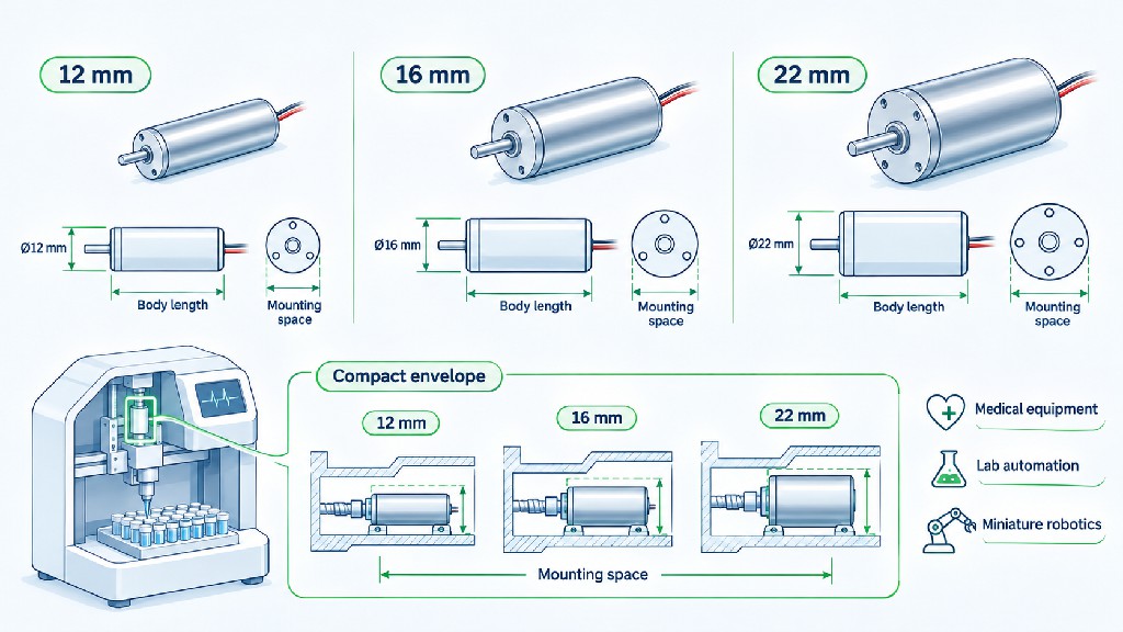
For a miniature coreless motor, diameter may be the first mechanical constraint, but it is rarely the only one. A nominal 12 mm, 16 mm or 22 mm motor family describes a relevant cylindrical size; it does not by itself establish the maximum outside diameter of every bearing housing, cable outlet, encoder or connector in an assembled product.
Start with the available cylindrical cavity and the required clearance. Measure the motor body, gearbox body, mounting boss, gearhead retaining features, screws and the full wire exit. Include the shaft projection, any encoder, a rear connector and the minimum acceptable cable bend radius. If a CAD model cannot be inserted and removed without interference, the apparent dimensional fit is not a manufacturable fit.
Axial length matters particularly in handheld surgical tools, portable pumps and compact robot joints. Adding a planetary gearbox can increase torque at the output but also increases length. Higher reduction ratios often require more gear stages; depending on the design, that adds axial length, moving components and efficiency loss. A gearmotor with the same nominal diameter can therefore have very different packaging characteristics across ratios.
Mounting geometry deserves equal attention. Request the bolt pattern, pilot diameter, shaft diameter and tolerance, D-cut or keyway dimensions, usable shaft length, concentricity and permissible fastening depth. A mismatch of only a few tenths of a millimetre can lead to poor alignment, excessive bearing load or expensive housing rework. Do not use a catalog image as a substitute for a dimensioned drawing.
The enclosure should also provide an appropriate thermal path. Mechanically supporting a motor with a compliant sleeve can reduce vibration transmission but may also restrict heat flow to the chassis. Conversely, a rigid aluminium mount may help cooling while transmitting gearmesh noise into a large resonant panel. Mechanical and acoustic design should be reviewed together.
When requesting a custom unit from , provide an annotated 2D mounting drawing and, preferably, a STEP model. The drawing should establish the maximum allowed diameter, maximum installed length, interface datum, shaft centerline and restricted regions for wires and connectors. This is a much more efficient starting point than asking for “the smallest motor possible.”
Reading Speed, Torque and Power Specifications Correctly
Three numbers are easily confused: no-load speed, rated speed and rated torque. No-load speed is measured or stated with little or no useful external load. Rated speed describes an operating condition associated with a specified load and other test assumptions. Rated torque is not the same as stall torque, and a gearbox's maximum permitted torque may be an independent limiting value.
A product title may prominently advertise 1,630 RPM, but if that figure is the no-load speed and the specification lists 1,385 RPM at rated load, the latter is a more relevant starting point for evaluating a continuous application. Real output speed will still depend on voltage, controller settings, load, temperature and the validity of the manufacturer's rating for the installation.
Mechanical output power is calculated from torque and speed:
Pout (W) = T (N·m) × n (RPM) / 9.5493.
For example, a gearmotor delivering 0.06 N·m at 445 RPM produces approximately 2.80 W of output mechanical power. That is consistent in scale with the published operating point of the 16 mm model discussed below. It does not mean electrical input power is 2.80 W; the winding, driver and gearbox consume additional power.
For a 24 V unit drawing 0.20 A from a DC supply, the nominal electrical input is 4.8 W. Comparing that input with the above mechanical output gives an illustrative whole-system efficiency of about 58%, if those values apply at the same measured operating point and to the same electrical boundary. The published values should be confirmed in a controlled test before using that percentage as a contractual efficiency specification.
A separate trap is to treat a motor's maximum output torque as available at every speed. In many DC motors, usable continuous torque decreases as thermal constraints become more demanding, and the driver or winding imposes a high-speed torque limit. A full speed–torque curve is therefore more meaningful than a single peak number. Request the curve for the actual winding voltage and intended driver rather than attempting to extrapolate from an unrelated motor.
High-Speed Coreless DC Motors: Benefits and Limits
A high speed coreless DC motor can be particularly useful when a small mechanism needs significant power without a large output shaft. For a given mechanical power, higher shaft speed means lower required torque. This permits a compact rotor and, if necessary, a gearbox that trades motor speed for output torque. Miniature pumps, rotary instruments, centrifugal devices and precision tools often exploit this relationship.
However, high speed is not synonymous with high usable output torque. As speed increases, the available voltage margin for current control can decrease because the motor generates back electromotive force. Bearing friction, aerodynamic losses, commutation behavior and rotor balance also become more important. The permissible upper speed must be checked for the exact motor and bearing arrangement.
Brushed and brushless machines differ in how speed affects wear. Brushed motors rely on sliding electrical contacts, so commutator conditions and brush life are part of the high-speed evaluation. Brushless motors remove that contact interface, although high-speed bearings, electronics and rotor retention still need validation. Portescap's explicitly identifies motor speed, lifetime, envelope and duty cycle as interconnected selection factors.
At very high speed, dynamic balance and mechanical resonance can dominate noise and reliability. A unit that meets a laboratory spin test may still vibrate in its final enclosure because the mounting arrangement changes the system's resonant modes. For a precision instrument, ask for the maximum permitted RPM, direction-reversal restrictions, bearing type, shaft runout and applicable vibration acceptance conditions.
When a gearbox is added, the motor-side speed is approximately output RPM multiplied by the gear ratio. A 100:1 reduction coupled to a 100 RPM output requires roughly 10,000 RPM at the motor shaft. But a ratio should not be selected by this arithmetic alone. The motor must develop enough torque at that speed, the gearhead must accept the input RPM, and friction and efficiency may change at operating temperature.
Finally, high-speed power is not free. A 12 mm motor can accelerate quickly yet have little continuous thermal capacity inside a sealed enclosure. A larger diameter or a longer motor may be the more compact system choice after considering the cooling hardware and transmission needed by a smaller alternative.
FRANK HU MOTOR 12 mm, 16 mm and 22 mm Coreless Geared Motor Selection Table
FRANK HU MOTOR publishes several compact motor-and-planetary-gearbox configurations. The table below selects representative actual catalog listings, rather than combining the best figures from different gear ratios into an imaginary product. Values refer to the geared output shaft. The published “rated” and “no-load” speeds are deliberately separated so that a buyer does not size a mechanism around the faster, unloaded figure.
| Published model / motor type | Diameter | Voltage | Gear ratio | Output no-load RPM | Output rated RPM | Published rated output torque | Published body / assembly length |
|---|---|---|---|---|---|---|---|
| , brushless | 12 mm | 12 V | 16:1 | 1,630 | 1,385 | 0.015 N·m | 39 mm |
| , brushless | 12 mm | 12 V | 64:1 | 407 | 346 | 0.056 N·m | 42 mm |
| , brushless | 12 mm | 12 V | 1,024:1 | 25 | 22 | 0.20 N·m | 48 mm |
| , brushless | 16 mm | 24 V | 16:1 | 750 | 630 | 0.040 N·m | 52 mm |
| , brushless | 16 mm | 24 V | 23:1 | 530 | 445 | 0.060 N·m | 52 mm |
| , brushless | 16 mm | 24 V | 509:1 | 23 | 21 | 0.30 N·m | 59 mm |
| , brushless | 22 mm | 24 V | 20.2:1 | 444 | 371 | 0.28 N·m | 72.7 mm |
| , brushless | 22 mm | 24 V | 75.9:1 | 119 | 99 | 0.95 N·m | 77.8 mm |
| , brushless | 22 mm | 24 V | 850.3:1 | 11 | 10 | 1.20 N·m | 82.9 mm |
| , brushed ironless | 22 mm | 24 V | 23:1 | 353 | 265 | 0.33 N·m | 52.5 mm |
Source and interpretation: Individual 12 mm and 16 mm entries come from their linked product pages; the 22 mm values come from the 24 V model tables in the linked brushless and brushed product families. The 22 mm brushless 1.20 N·m ceiling is explicitly identified in that family as a gearbox continuous-torque limit. The 22 mm brushed family separately states a 2.00 N·m gearbox-limited ceiling for certain high-ratio versions. These limits are not interchangeable and are not guaranteed stall torques. Catalog length labels follow the vendor's descriptions; obtain the latest dimensional drawing to determine whether each assembly measurement includes any projecting shaft, cable or connector. Values may change by variant or revision.
What the table reveals
The 12 mm family is relevant when there is very limited diameter and modest output torque. Its lower-ratio 16:1 example provides much higher output speed than the 1,024:1 variant, while the latter delivers much more nominal output torque at only 22 rated RPM. That is a transmission trade-off, not evidence that the motor winding itself has become vastly more powerful.
The 16 mm family occupies a useful middle ground. At 24 V, the 23:1 model lists 445 rated output RPM and 0.06 N·m, while the 509:1 option lists 21 rated RPM and 0.30 N·m. A compact actuator that needs several hundred RPM could therefore be better served by a lower ratio, even if the higher ratio has the more impressive torque number.
The 22 mm brushless family provides more output torque and many intermediate ratios. At 75.9:1, one published 24 V variant is rated at 99 RPM and 0.95 N·m; at 850.3:1, the rated speed drops to 10 RPM and the torque specification reaches the gearbox's stated 1.20 N·m ceiling. Selecting the maximum ratio only makes sense if the application needs very low speed and can accept the accompanying packaging, backlash and efficiency implications.
There is also a 22 mm brushed ironless geared family. It should be evaluated separately for shorter-duty or simpler-control applications. A model with a shorter listed assembly length may be attractive in a space-constrained machine, but the brush-life requirement must be included in that decision. Browse the broader for available configurations and request a confirmed motor-plus-gearhead specification rather than mixing values from separate products.
Choosing a Micro Planetary Gearbox
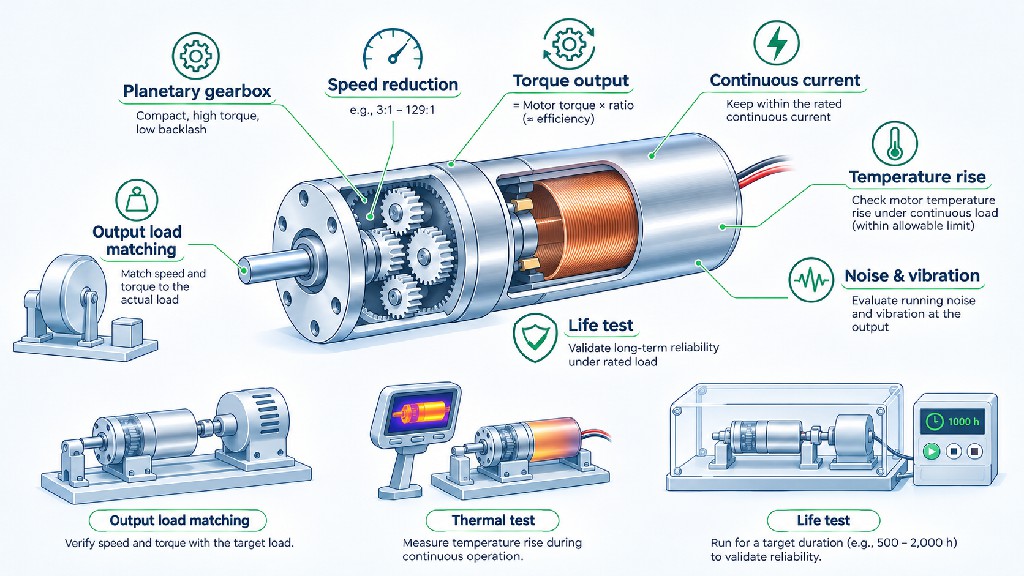
A coreless geared motor is more than a fast miniature motor with a reduction ratio attached. The gearhead changes output speed, torque, inertia, acoustics, mechanical stiffness and reliability. Planetary gearboxes are popular in cylindrical microdrives because they can package multiple gear contacts around a central axis, but their real performance depends on the tooth geometry, bearing support, lubrication, material selection and number of reduction stages.
For a first estimate, let i be the reduction ratio, η the gearbox efficiency at the intended operating point, nm the motor speed and Tm the motor-shaft torque. Then:
Output speed ≈ nm / i Output torque ≈ Tm × i × η Required motor torque ≈ required output torque / (i × η).
These equations describe an idealized steady-state power flow. They do not replace the gearbox's published output torque limit, allowable input speed, intermittent rating, starting friction or mechanical efficiency curve. Efficiency is not generally constant across every speed, load, temperature and rotation direction.
Suppose an actuator needs 0.30 N·m at 100 RPM. With a hypothetical 20:1 gearbox operating at 75% efficiency, the motor must supply approximately 0.020 N·m at 2,000 RPM. This is a calculation example, not a claim that a specific FRANK HU MOTOR 20:1 gearbox has 75% measured efficiency. The engineer should next check whether the candidate motor can sustain that 20 mN·m at the resulting speed and whether the gearhead can carry 0.30 N·m continuously.
The real gear ratio may be 20.2:1 rather than an integer 20:1, as illustrated by the 22 mm product family. For precision positioning, that difference may affect the conversion between motor encoder counts and output travel. Use the actual catalog or confirmed production ratio in the motion controller's scaling parameters.
Three additional gearhead constraints are routinely overlooked. Backlash creates a dead zone when direction reverses. Radial and axial output-shaft loads can damage miniature bearings even if transmitted torque is acceptable. Shock and repeated peak loads can overload tooth contacts during startup or an unexpected stall. If the gearmotor drives a belt pulley, cam or cantilevered gear, add an external bearing when the calculated side load exceeds the gearhead's limit.
A gearhead also creates an efficiency-versus-ratio trade-off. More stages commonly add losses and gearmesh interfaces. Illustrative data from show why gearhead efficiency and backlash belong in the specifications instead of being assigned one universal number. Those maxon values are examples of another supplier's products; do not apply them directly to FRANK HU MOTOR gearheads.
Matching Low Rotor Inertia with Load Inertia and Gear Ratio
Gear reduction changes how load inertia appears at the motor shaft. For a relatively rigid transmission with ratio i, a useful first-order model is:
Reflected load inertia at the motor ≈ output load inertia / i².
For example, an output load of 2.0 × 10⁻⁵ kg·m² behind a 10:1 gearbox appears as approximately 2.0 × 10⁻⁷ kg·m² at the motor shaft, before adding the gearbox's own inertia. At a 20:1 ratio, the reflected component falls to 5.0 × 10⁻⁸ kg·m². This is one reason a gearbox can help a small motor accelerate a larger mechanism.
However, the apparent benefit has a cost. A higher ratio requires the motor to rotate farther and generally faster for each output movement. The gearhead's internal inertias and losses are not all reduced by the same factor. For a rapidly cycling axis, those effects must be included in a dynamic model rather than assuming that larger ratios always improve response.
A complete simplified acceleration calculation includes motor-rotor inertia, applicable gear-stage inertia and reflected load inertia:
Motor acceleration torque ≈ (Jmotor + Jgear,equivalent + Jload/i²) × motor angular acceleration.
Add the torque required to overcome friction and external process loads, converted through the transmission. For a vertical actuator, account for gravity; for a pump, include pressure variation; for a geared wheel, include rolling resistance and ground contact. The correct gear ratio minimizes the total system cost and achieves the required motion profile, rather than minimizing only the reflected load inertia.
An encoder can improve control but does not remove backlash. A motor-mounted encoder measures rotation before the gearhead; it cannot directly detect small load movements that occur within backlash or torsional deflection. For a precision robotic joint or metrology axis, consider whether an output-side encoder is necessary. The distinction between commutation sensors, motor encoders and load-position feedback is discussed in the .
Continuous Current, Temperature Rise and Thermal Design
Thermal capacity is often the most important reason an otherwise appealing miniature motor fails an application. A small, lightweight motor has limited surface area and may be surrounded by plastic, foam, adhesives or a sealed enclosure. The motor can reach an unacceptable winding temperature while its external shell still feels only warm. Continuous performance must therefore be validated in the actual mounting and ambient conditions.
Copper winding heating is approximately related to I²R, where I is the relevant winding current and R is winding resistance at the operating temperature. Doubling current can increase resistive heating by roughly a factor of four when resistance is assumed constant. In reality, copper resistance itself rises as the winding becomes hotter, and additional magnetic, mechanical and electronic losses also contribute to total heat.
Do not confuse rated current, driver current limit, startup current and stall current. A motor may tolerate a high current briefly without tolerating it continuously. The drive may also report DC bus current while the phase winding carries a different RMS current. For BLDC systems, request clarity about which current is specified and how it was measured.
A useful first-pass model of steady-state winding temperature rise is:
Temperature rise ≈ dissipated motor heat × thermal resistance to ambient.
If a motor dissipates 2 W and its effective winding-to-ambient thermal resistance is hypothetically 15 K/W, the corresponding steady-state temperature rise would be approximately 30°C. This is an illustrative thermal calculation only. It is not a specification for any product in the table, and it does not cover a rapidly changing operating profile. Real motor assemblies have multiple thermal paths and thermal time constants.
For intermittent operation, assess the entire duty cycle. A mechanism running for five seconds and resting for fifty-five seconds may cool between cycles, but not necessarily to ambient. Frequent starts can also consume much more current than steady operation. A simple duty percentage is not enough if the torque peaks, ambient temperature or thermal time constants are not known.
Thermal design measures may include better contact to a metal chassis, reduced gearbox friction, a longer motor body, a more appropriate winding, lower acceleration demand or a change from brushed to brushless architecture where contact losses and lifetime justify it. Heat should be measured at stabilized worst-case operation with the intended controller, housing, supply tolerance and cable routing. For products used close to patients or skin, separately evaluate touch-temperature and applicable system safety requirements, not just the motor's insulation class.
Noise, Vibration, Smooth Motion and Electromagnetic Interference
Coreless construction can contribute to smooth rotation because it removes conventional tooth-related cogging from the relevant ironless winding arrangement. This is useful in optical instruments, handheld devices and miniature pumps. Nevertheless, a coreless motor is not automatically silent. Audible and measurable disturbances also come from shaft bearings, rotor imbalance, gearbox tooth contact, controller switching, mounting resonance and the driven mechanism itself.
A brushed motor adds mechanical commutation noise and electrical disturbances generated at brush contacts. A brushless motor avoids that specific source but introduces electronic switching and drive-current ripple. At low speed, an unsuitable commutation algorithm can produce noticeable torque ripple even when the motor's magnetic design has very low cogging. A smooth-sounding unloaded prototype may behave differently when attached to a high-ratio gearbox and a real load.
For quiet instruments, define an acoustic test condition: microphone location, environmental background, speed, load, enclosure, mounting surface and direction of rotation. Sound-pressure level without a measurement distance or test setup is difficult to compare. For a laboratory analytical instrument, vibration transmitted to the measurement head may matter more than airborne noise. Accelerometer measurements, motor-shaft runout inspection and modal testing can reveal problems that a simple decibel reading misses.
Electromagnetic interference (EMI) must also be addressed as a system issue. Brushed machines may need appropriate motor-terminal suppression, carefully selected capacitors or filtering consistent with the controller. BLDC drives can benefit from controlled cable routing, suitable grounding, current-loop design, phase-wire management and filters chosen after emissions testing. Adding an arbitrary capacitor across BLDC phase wires can create excessive switching current and is not a universal remedy.
Keep motor power conductors away from sensitive analog sensors and encoder wiring where feasible. Evaluate common-mode current paths, shielding termination, switching-edge behavior and the location of power-supply return currents. The most appropriate EMC test standard depends on where the finished product is used. For industrial electronic systems, the IEC maintains . Compliance must be assessed for the relevant equipment and applicable standard set; a motor component's certification does not establish that the completed machine passes EMC tests.
Low noise and low EMI are valuable commercial features, but they need measurable acceptance criteria in the OEM specification. Ask for motor, gearbox and controller samples together so the acoustic and electrical performance can be evaluated under representative conditions.
Motor Lifetime and Reliability: What Should Be Validated?
A buyer may ask for a “10,000-hour coreless motor,” but a credible answer must identify the operating conditions behind any lifetime estimate. Hours at no load, hours at rated torque, high-temperature running hours and repeated startup cycles are not equivalent. A supplier's life claim is meaningful only when the commutation design, bearings, speed, temperature, environment and failure definition are understood.
For a brushed ironless motor, brush and commutator wear must be included. Contact materials behave differently under low current, high current, high humidity and repeated reversal. In a small intermittent instrument, the number of on/off and reverse cycles may be a better predictor of service requirements than running hours alone. At high rotational speed, brush wear can accelerate, particularly when the system operates outside its intended electrical or mechanical range.
For a coreless brushless DC motor, the absence of brushes removes one significant wear mechanism. It does not remove bearing wear, lubricant aging, magnet-related limits, winding insulation degradation or driver failures. The gearhead may become the first component to fail even if the motor remains electrically healthy. Gear tooth wear, backlash growth, grease migration, seal condition and bearing contamination should therefore be included in the reliability plan.
A complete qualification program should begin with a clear application-specific failure definition. For example, a syringe pump may be considered to have failed when its delivered flow or positioning error exceeds a limit, even if the motor still turns. A miniature robot joint may be unacceptable after backlash increases beyond a specified angle. A handheld instrument may fail its product requirement when exterior temperature, sound level or vibration crosses a safety or usability threshold.
Useful tests include stabilized full-load temperature measurements, repeated start-stop and reversal cycling, low-voltage startup, overvoltage tolerance within rated limits, acoustic and vibration trending, output shaft radial-load evaluation, gearbox endurance and contamination exposure where relevant. Capture current, speed, temperature and performance at the beginning, during and end of testing. Record the exact load profile and environmental conditions so another engineering team can reproduce the result.
Reliability decisions should combine supplier evidence with application-level testing. Incoming inspection can screen dimensional consistency and no-load electrical behavior, but it cannot replace lifetime validation. For production procurement, ask which manufacturing characteristics are controlled across lots, which tests are performed on every unit, and which are performed on samples. Also clarify traceability, change notification and what constitutes a warranty claim.
Coreless Motors for Medical Devices and Laboratory Instruments
A coreless motor for medical devices may be selected for compactness, responsive movement and low noise, but the application's clinical and regulatory context determines which specifications matter most. Common engineering opportunities include handheld diagnostic instruments, portable pumps, syringe actuators, dosing mechanisms and laboratory sample-handling equipment. These are potential applications, not a claim that a specific catalog motor has been qualified or approved for a particular medical use.
Consider a battery-powered syringe pump. The designer needs accurate linear travel, controlled force, predictable startup and low acoustic disturbance. A motor may drive a lead screw directly or through gearing, and closed-loop feedback may measure motor motion or actual syringe displacement. A small, efficient coreless motor may help reduce power consumption, but changes in syringe friction, viscosity, occlusion and battery voltage can still dominate the actual load requirement.
For a laboratory pipetting or microfluidic device, fast starts and stops may favor low inertia. However, repeatability depends on the whole mechanism: screw lead accuracy, compliant tubing, seals, backlash, feedback, controller tuning and fluid behavior. Specifying an encoder with very high resolution does not compensate for a flexible coupling or a backlash-limited gearbox.
A handheld clinical instrument may be limited by diameter, weight and user comfort. In this case, motor diameter and total system length must be balanced against sustained temperature rise, gearbox noise and mechanical vibration. A slightly larger motor that runs cooler at the required load can be preferable to a smaller motor operated close to its maximum limit.
Medical product developers also need a formal risk and verification process. provides a framework for medical-device risk management, while the relevant addresses basic safety and essential performance of applicable medical electrical equipment. Other device-specific, software, EMC, biocompatibility, cleaning or sterilization requirements may also apply. A component-level CE or RoHS statement must not be mistaken for approval of the finished medical device.
Portescap's illustrates why a pump must be evaluated as a combination of motor, gearbox, drive and feedback rather than as a motor alone. When requesting an OEM medical-device sample, disclose the intended cleaning method, operating temperature, expected duty cycles and whether the product will be subjected to sterilization. Do not assume an ordinary catalog motor is autoclave-compatible, implantable, sterile or suitable for patient contact.
Coreless Motors for Miniature Robotics and Precision Tools
Small robotics and portable automation place different demands on motor systems. In a gripper, the main concerns may be force repeatability, fingertip safety and the ability to survive occasional stalls. In a miniature robot joint, backlash, stiffness and positional feedback may outweigh maximum no-load RPM. In a mobile sensor platform, low power consumption and quiet movement may matter more than peak torque.
A 12 mm geared brushless motor is a reasonable candidate to investigate when the mechanism has an especially restrictive cylindrical cavity and a light output load. The 16 mm family may be a better packaging and torque compromise for a compact clamp or instrument feed mechanism. A 22 mm family may provide more appropriate output torque for a miniature joint or a demanding actuator, provided the extra diameter and length can be accommodated. These are screening suggestions, not application-specific guarantees.
For a robotic end effector, never estimate the motor from the desired gripping force without calculating the transmission geometry. If a finger mechanism has an effective moment arm of 20 mm and requires 10 N of tangential force, the corresponding ideal torque is 0.20 N·m before friction, acceleration and safety margins. The actual relationship may vary considerably through the stroke because linkages and cams change mechanical advantage.
For a miniature rotary tool, the required mechanical output power and the allowable spindle speed become central. A high-ratio gearhead that is useful for an actuator may be a poor choice for a fast cutting spindle because it sacrifices speed and adds gearmesh losses. A low-ratio design, direct drive or a different motor architecture may be better. Bearing capability and tool-induced radial load also deserve particular attention.
A useful distinction for procurement is between prototype suitability and production suitability. A motor can demonstrate motion in a single benchtop prototype without providing stable acoustic performance, consistent assembly dimensions or adequate long-term reliability across a production batch. OEM qualification should specify the acceptable spread in speed, current, dimensions, vibration and output backlash.
Worked Selection Example: A 12 mm Laboratory Feeder
Assume a laboratory feeder must fit inside a cylindrical opening with a maximum motor/gearhead diameter of approximately 13 mm. The mechanism needs 300 RPM and 0.030 N·m at its output shaft in normal operation, with a short intermittent duty cycle. The device uses a regulated 12 V supply and has enough axial space for a 42 mm motor/gearbox body plus the necessary shaft and connector clearance.
A published candidate is the . Its catalog specifies 346 rated output RPM and 0.056 N·m rated output torque with a 64:1 planetary gearbox. At the initial screening level, the required 300 RPM and 0.030 N·m sit below those published values. The rated speed is a more meaningful figure to compare than its 407 RPM no-load speed.
The load's required output mechanical power is approximately 0.94 W (0.030 × 300 / 9.5493). This is not the electrical power consumed by the device, and it should not be used as a substitute for checking the motor's rated current and thermal condition. In addition, the required speed and torque form a paired operating point; separately being below two headline limits is not enough if the motor's full torque-speed curve or controller behavior differs from the assumed operating conditions.
The next engineering questions are whether the mechanism's startup torque exceeds 0.056 N·m, whether 300 RPM can be regulated smoothly under load, whether the 3 mm output shaft fits the coupling, and whether the product's published length convention matches the available installation space. A prototype should be tested at the highest expected ambient temperature and with the maximum anticipated friction, including the effect of worn or contaminated mechanical parts.
The selection would change if the feeder had to run nearly continuously or required very rapid reversals. In those cases, the motor, gearbox and driver must be reviewed for repeated peak current, thermal equilibrium and directional backlash before release.
Worked Selection Example: A 16 mm Precision Dispensing Axis
Consider a compact dispensing mechanism with a 24 V power supply. The output needs roughly 400 RPM and 0.045 N·m during its normal dispensing stroke. The available diameter is 17 mm, while the total allowed assembly length must be verified against the installed shaft and cable arrangement.
Two catalog candidates illustrate the value of comparing the same motor family with different gearbox ratios. The lists 630 rated RPM but only 0.040 N·m rated output torque. It may have adequate speed, yet its published torque is already lower than the requested steady load. Selecting it just because the gearbox ratio is lower could result in overheating or inadequate torque margin.
The instead lists 445 rated output RPM and 0.060 N·m rated output torque. These figures provide a better preliminary match to the stated requirements. Its published body length is 52 mm, which still needs to be checked against the real envelope. The published rated current is 0.20 A; this should not be treated as an unconditional upper limit for all transients or controllers.
For the 400 RPM, 0.045 N·m load, calculated output mechanical power is approximately 1.88 W. The remaining design questions include whether the required speed can be maintained during the highest-viscosity dispensing condition, whether startup torque is greater than steady torque, and whether speed regulation creates objectionable pulsation in the dispensed material.
This comparison shows why choosing by diameter or the maximum no-load speed can be misleading. The better candidate is the one whose rated operating point and actual performance curve match the required output motion with adequate thermal and reliability margin.
Worked Selection Example: A 22 mm Robotic Actuator
Assume a miniature robot actuator requires a nominal 90 RPM output speed and 0.50 N·m output torque at a 24 V supply. The assembly can accommodate a 22 mm cylindrical motor/gearhead body, but the designer wants to limit length and avoid unnecessary high-ratio gearing.
The published has a 75.9:1 ratio and lists 99 rated RPM, 0.95 N·m rated torque and 77.8 mm total length in the supplier's table. It is a plausible starting point. The application requires about 4.71 W of mechanical output at 90 RPM and 0.50 N·m. A dynamic calculation must still check the acceleration spikes, stopping torque and operating temperature.
By contrast, the 850.3:1 option in the same family is listed at only 10 rated RPM, so its higher reduction ratio would not satisfy the 90 RPM speed requirement. The 52.7:1 model lists 143 rated RPM and 0.67 N·m rated torque and may also deserve evaluation if the controller and thermal conditions support the intended 90 RPM point. The shorter 52.7:1 assembly can be attractive, but neither option should be accepted without comparing the full output torque-speed curves and gearbox backlash.
If the robot joint must position precisely after reversing direction, determine whether the gearbox's backlash and torsional compliance fit the accuracy budget. An encoder on the motor shaft does not directly remove this error. Consider output-side sensing, a lower-backlash gearhead or another transmission architecture if the final joint requires very fine bidirectional positioning.
This example also illustrates why the catalog's 1.20 N·m gearhead limit matters. Even when a larger ratio mathematically predicts more torque, the actual continuous output must remain within the motor and gearhead limits and the supplier's approved duty cycle.
OEM Customization: Which Specifications Are Worth Requesting?
The commercial advantage of a custom miniature motor should be measured in easier integration, reliable performance and lower total product cost—not simply in a different label on a standard unit. For many equipment manufacturers, modest changes to a proven motor family can be more practical than designing an entirely new electromagnetic platform.
A custom shaft is often the most immediately useful modification. Length, diameter, D-cut geometry, surface finish, thread, shoulder and tolerance can be adapted to the coupling or driven mechanism if manufacturing and bearing limits permit. An appropriate shaft design can eliminate an extra adapter and shorten the assembled system. However, a thinner or longer shaft may reduce allowable bending strength and increase runout sensitivity; the design must be checked rather than approved by appearance alone.
A winding or voltage variant can also be valuable when the machine uses a particular battery pack or 12 V/24 V bus. Winding changes influence resistance, speed constant, torque constant and current requirements. A 24 V winding is not just a 12 V winding with a different label. The motor and driver should be matched for the true input voltage range, current regulation and peak demand.
Other possible OEM topics include gearbox ratio, lubrication, output bearing arrangement, cable length, wire colors, connectors, Hall feedback, encoder interface, mounting details and packaging. Their feasibility depends on the specific product family, minimum order volume, tooling, process capability and validation requirements. Avoid treating all options as universally available for every diameter.
For an OEM quotation, separate mandatory design requirements from preferences. If the diameter is non-negotiable but the length can increase by 5 mm, state that explicitly. If a certain connector is preferred but an equivalent is acceptable, identify the accepted alternatives. Such information helps the technical team propose a practical motor family without unnecessary redesign.
FRANK HU MOTOR's provides reference configurations for initial screening. For a specification-based quote, use the and request the matching dimensional drawing, electrical characteristics, speed-torque curve and drive recommendations for the specific part number.
What to Include in a Coreless Motor RFQ
A precise request for quotation can shorten the exchange between a product-development team and the supplier considerably. Instead of saying “please quote a small coreless motor,” provide the engineering conditions that determine whether the proposed system will actually work.
Mechanical requirements: state the maximum motor and gearbox diameter, allowable body and total assembly length, mounting hole geometry, shaft dimensions and tolerances, allowed radial/axial load and the preferred CAD file format. Attach the machine's mechanical mounting drawing or STEP file. If a bearing or coupling is already selected, include its interface dimensions.
Motion requirements: specify output speed in RPM, continuous torque in N·m or mN·m, peak torque and peak duration, acceleration time, reversals per minute, expected backlash or position accuracy, and whether holding torque or power-off holding is necessary. If the axis is linear, provide screw lead, travel distance, load force and required cycle time so the supplier can verify the conversion to rotational load.
Electrical and control requirements: give the nominal and minimum/maximum supply voltage, driver type or preferred interface, allowed continuous and peak current, the required direction and speed-control modes, and any existing encoder or Hall wiring requirements. Do not assume a generic BLDC driver will be electrically or mechanically compatible with a very small low-inductance motor.
Environmental and reliability requirements: include ambient temperature, enclosure thermal conditions, humidity, contamination exposure, acoustic limit and measurement method, expected service life, number of starts and stops, cleaning method and any relevant regulatory or EMC requirements. For medical-device development, identify the applicable risk controls and test documentation expected from suppliers without implying the motor itself is the certified finished device.
Commercial requirements: include prototype quantity, planned annual volume, target delivery schedule, country of final assembly, desired production consistency, quality documentation, change-control requirements and whether a sample qualification period is required. Request separate confirmation of development costs, custom tooling, lead time and any additional tests that are outside the standard offering.
The objective is not to create paperwork for its own sake. It is to ensure that the supplier and buyer are discussing the same mechanical output, duty cycle and accepted failure criteria. A complete specification also allows a technically stronger alternative to be considered when the original diameter, winding or gear ratio is impractical.
Qualification Checklist Before Mass Production
A well-designed proof-of-concept demonstrates that the mechanism moves. Production qualification demonstrates that it moves correctly, repeatedly and safely under the specified conditions. Before committing to a large OEM order, test a representative set of assemblies with the intended controller and final mechanical mounting.
At minimum, compare the delivered dimensions against the latest approved drawing and verify shaft alignment, mounting fit, cable clearance and connector polarity. Measure no-load current and speed at the specified voltage, then evaluate loaded speed, current and output torque at a controlled operating point. Where gearbox backlash is critical, test it at a defined torque and direction-change method rather than quoting a vague “precision gearbox” description.
Run thermal testing at the expected worst-case continuous or repeated duty and at the relevant maximum ambient temperature. Inspect both the motor and the surrounding device enclosure. Perform low-voltage startup tests, maximum-load reversals, abnormal-load responses and whatever stall protection is applicable. High-current or prolonged-stall testing must use appropriate protection and should not exceed the supplier's permitted safe test conditions.
For quiet or precision devices, establish a repeatable vibration and acoustic baseline. Observe whether noise grows after endurance testing or after thermal cycling. For electronic devices, test the motor and driver as installed within the full product so cable lengths, shielding, grounding and nearby sensitive circuits are represented.
Reliability sampling should reflect product risk and production volume. Where possible, compare multiple manufacturing lots and track trends, not merely the average result from one prototype. Record inspection criteria and approval responsibility in the engineering change process so a later revision to a shaft, magnet, winding or gear lubricant cannot silently invalidate earlier test evidence.
Common Coreless DC Motor Selection Mistakes
The first mistake is shopping by no-load RPM. A motor can spin rapidly without producing the required torque at that speed. Use the rated operating point and request a load curve for a realistic assessment.
The second is assuming the highest gear ratio is always best. More reduction lowers output speed and can increase backlash, length and transmission loss. Published gearbox torque limits still apply even when a simple ratio calculation suggests a much larger output value.
The third is treating coreless and brushless as synonyms. A brushed coreless rotor and a slotless brushless stator are different constructions with different wear mechanisms and driver requirements. Verify both the internal winding arrangement and commutation type.
The fourth is underestimating duty-cycle heating. A small motor that works for ten seconds in a demonstration may be unsuitable for hours of repeated operation in a closed plastic housing. Evaluate the actual current and temperature history.
The fifth is ignoring the mechanical transmission. Backlash, bearing support, coupling misalignment, lead-screw friction and external side loads can dominate performance even when the motor itself is correctly selected.
The sixth is assuming a Hall sensor is a precision position encoder. Hall sensors may provide adequate rotor-state feedback for commutation, but they do not necessarily deliver the output-position accuracy needed by an inspection or robotic axis. Choose feedback according to the system's real control objective.
The seventh is interpreting a component claim as finished-product approval. Medical devices, laboratory equipment and industrial electronics may require system-level safety, EMC and reliability evaluation. Obtain the documents appropriate to the exact product and target market.
The eighth is submitting a request without mounting drawings. A motor with suitable torque but the wrong pilot, shaft length or wire exit is not an efficient purchase. Share a dimensioned drawing before committing to a custom or production order.
Frequently Asked Questions
What are the most important coreless DC motor advantages?
The key potential advantages are low rotating inertia, responsive acceleration and deceleration, smooth motion due to the absence of conventional tooth cogging, and attractive performance in a compact package. Actual efficiency, lifetime and noise still depend on the winding, magnets, commutation, bearings, controller, load and thermal environment. A coreless design is not automatically the strongest or most efficient option in every application.
Is an ironless DC motor the same as a coreless DC motor?
The terms are often used interchangeably for a motor whose winding assembly lacks the conventional iron core found in many armatures or slotted stators. However, the terms describe construction, not necessarily commutation. Ask whether the motor is brushed or brushless and request the construction drawing if the distinction is important to your project.
What is the difference between a coreless motor and a brushed motor?
This comparison mixes two different characteristics. Coreless describes the winding or magnetic structure; brushed describes mechanical current commutation. Many coreless DC motors are brushed motors. A meaningful comparison is therefore coreless brushed versus iron-core brushed, or coreless brushed versus slotless brushless, depending on what the project is evaluating.
Are coreless brushless motors always better for medical devices?
No. Brushless technology can be attractive for long service life and repeated operation because it removes brush-contact wear, but it requires electronic commutation and appropriate system verification. A brushed ironless motor may be a sensible choice in a short-duty, space- or cost-constrained device. Regulatory suitability is determined at the applicable device and system level, not by the word “brushless.”
Which small diameter DC motor should I choose: 12 mm, 16 mm or 22 mm?
Choose the diameter only after defining the actual required output torque, speed, duty cycle and installation envelope. A 12 mm geared design may suit a light mechanism; a 16 mm variant may offer a useful intermediate size; and a 22 mm model may be suitable when higher geared output torque is required. Compare specific part numbers under the same operating conditions rather than comparing the maximum advertised number from each family.
Does a coreless motor need a gearbox?
Not always. Direct drive avoids gear losses and backlash and may be preferable for a fast, light load. A gearbox is useful when the load requires lower speed and higher output torque than the bare motor can provide efficiently. The decision should include motor efficiency, gearhead efficiency, total length, backlash, shaft loading and required position accuracy.
Can a miniature coreless motor hold a load when power is removed?
Do not assume that it can. Many coreless motors and planetary gearheads are backdrivable to some degree. Friction may resist movement, but it is not a guaranteed safety-rated holding method. For gravity-loaded or safety-critical axes, specify a suitable brake or other independent restraint and verify the complete system.
How can I reduce vibration and electromagnetic noise?
Start by identifying whether the disturbance originates from the motor, gearbox, controller, mounting system or external load. Use appropriate balance and bearing quality, a suitable control strategy, effective cable routing and grounding, and application-specific filtering. Validate in the finished enclosure; component-level tests alone may miss resonances or EMI coupling created during integration.
Can FRANK HU MOTOR customize a coreless geared motor from my drawing?
Submit your drawing and the required output operating point through . Possible requests can involve shaft geometry, winding, cable or connector details, gear ratio or mounting interface, subject to engineering review and model-specific manufacturing feasibility. Ask for confirmation of the proposed dimensions, torque-speed performance, duty rating, sampling and production quantities before treating the design as approved.
Choose the Motor System, Not Just the Motor Label
A successful coreless DC motor selection begins with the machine's actual motion requirement and ends with a tested motor, driver, gearbox and mechanical assembly. Ironless construction can deliver real advantages in compact, responsive equipment, but those benefits only reach the end product when the motor is matched to its load and operating environment. The best 12 mm solution may be inappropriate for a high-torque actuator; the highest-ratio 22 mm gearmotor may be too slow for a fast mechanism; and a brushless design may not justify its extra electronics in every short-duty application.
For engineers and buyers planning a precision instrument, miniature pump, robotic mechanism or OEM device, use the to shortlist a few actual part numbers. Then compare their rated output speed and torque, not just their product titles. Confirm current, thermal capacity, gearhead limits, shaft loading and feedback against the intended duty cycle.
Have an installation drawing or a target motion profile? with your 2D mechanical drawing or 3D STEP file