BLDC motor selection connects the application load, required shaft torque, operating speed, acceleration, duty cycle, power source, controller, and thermal environment into one complete motion system. A motor that looks powerful on a shopping page may still stall during startup, overheat in an enclosure, or fail to maintain speed after the mechanical load increases.
This guide explains how to choose a BLDC motor for practical machinery rather than relying on isolated catalog numbers. It covers the equations behind brushless DC motor sizing, the differences between 24V and 48V operation, rated versus peak versus stall torque, feedback and commutation, speed–torque curves, motor constants, and the engineering checks required before ordering. It also demonstrates an actual 24V, 3,000 RPM motor from FRANK HU MOTOR's catalog and proposes a lightweight sizing calculator for preliminary project estimates.
Whether you are building a compact fan, an industrial conveyor, a laboratory pump, an automated guided vehicle, or a precise motion axis, the same principle applies: size the motor for what the machine must do, then verify that the motor, driver, and power supply can do it together.
Quick answer: Start by determining the load's required continuous torque (N·m) and speed (RPM) at the relevant shaft. Add the torque needed for acceleration and identify the longest overload interval. Calculate mechanical power as P (W) = Torque (N·m) × RPM / 9.5493. Check the complete speed–torque envelope, choose a compatible 24V or 48V system, confirm sensor and drive requirements, and validate thermal limits against the actual duty cycle. You can then compare candidates in the or .
What Is a BLDC Motor, and How Does It Work?
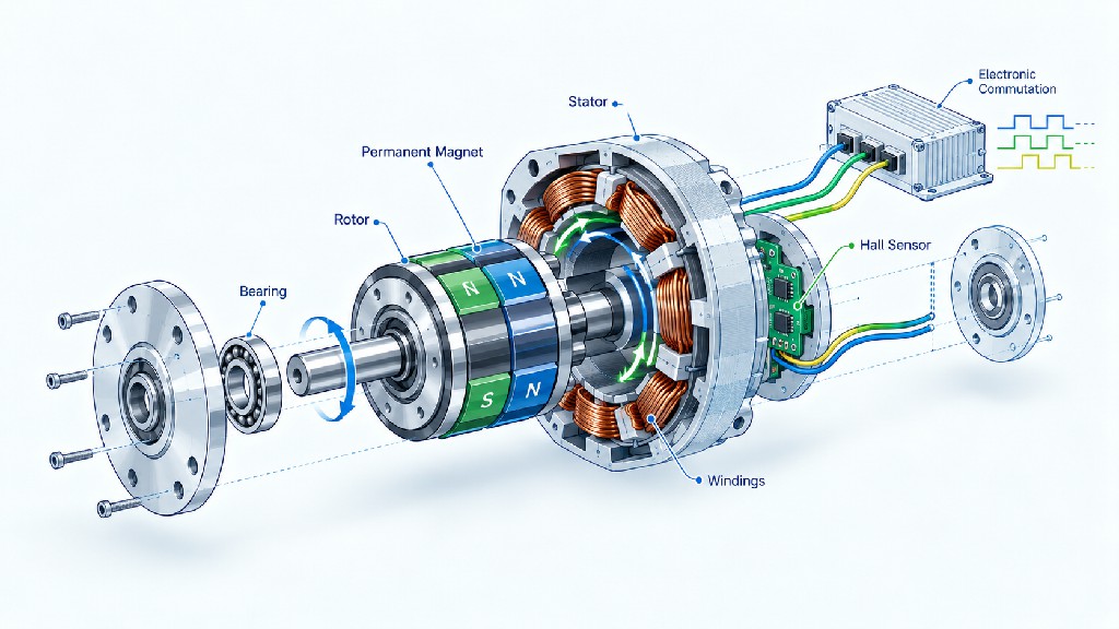
A brushless DC (BLDC) motor is a permanent-magnet motor whose winding currents are switched electronically rather than by mechanical brushes and a commutator. In a common three-phase design, the stator contains wound copper coils, while the rotor carries permanent magnets. A semiconductor inverter energizes the stator phases in a controlled sequence, creating a rotating magnetic field that pulls the rotor along. A controller decides when and how strongly to energize the phases using measured or estimated rotor position.
The basic hardware contains five interacting elements: the rotor and its magnets, the stator and copper windings, bearings and shaft, an electronic power stage (usually six switching transistors in a three-phase bridge), and control logic. Depending on the design, the motor may also include Hall-effect position sensors, an encoder, a brake, a gearbox, temperature monitoring, or integrated electronics. The motor cannot normally be connected straight to a DC supply and expected to run correctly; it needs suitable electronic commutation, whether provided by a separate driver or integrated controller.
A widely used method is six-step or trapezoidal commutation. The driver switches phase combinations according to the rotor's electrical position. More sophisticated approaches use sinusoidal commutation or field-oriented control (FOC) to regulate the torque-producing current with improved smoothness in suitable designs. The controller's capabilities—not the term “brushless” alone—determine whether the complete system supports accurate speed control, low-speed torque, quiet motion, or position control. For the underlying construction and operating principles, see Microchip's and Texas Instruments' .
BLDC systems are popular because they avoid brush replacement and can deliver high power density and responsive electronic control. However, brushless does not mean maintenance-free: bearings wear, seals can age, electronics can fail, and poor heat dissipation can damage insulation or magnets. Nor does every brushless motor behave like a servo system. A servo application requires an appropriate feedback and control architecture, often including an encoder and properly tuned position or velocity loops.
BLDC vs. brushed DC, stepper, and servo systems
| Motor/system | Typical strength | Main trade-off | Good fit |
|---|---|---|---|
| Brushed DC motor | Straightforward voltage control and simple electronics | Brushes wear; commutation creates electrical noise | Cost-sensitive auxiliary mechanisms |
| BLDC motor with basic speed drive | Efficient rotating motion and good controllability | Requires electronic commutation and compatible driver | Fans, pumps, rollers, conveyors |
| Stepper motor | Convenient commanded incremental motion | Torque falls with speed; open-loop systems may miss steps | Low-speed indexing and compact positioning |
| BLDC/AC servo system | Closed-loop speed, torque, and position performance | More expensive electronics, feedback, and tuning | Robotics, precision axes, dynamic automation |
These are general system-level comparisons, not absolute rankings. A closed-loop stepper may outperform a basic sensorless BLDC drive on positioning, while a servo motor may itself be a brushless permanent-magnet machine. The actual comparison should be between complete systems at the specified operating point.
The Seven Inputs Every BLDC Motor Selection Should Start With
Before browsing a catalog, write down the application's requirements. This exercise prevents a common purchasing mistake: selecting a motor because its nominal power seems sufficient while overlooking starting torque, operating time, or gearbox losses.
-
Required load speed: What shaft speed or linear travel rate must the machine deliver under load? Is there one fixed operating point or a wide speed range?
-
Continuous load torque: How much resistance must the motor overcome during steady operation? Include friction, gravity, process load, and any transmission losses.
-
Acceleration and peak torque: How quickly must the load start, stop, reverse, or recover from an impact? How long does each peak last?
-
Supply conditions: Is the source a regulated 24V DC supply, a 48V battery, or another bus? What are the real minimum and maximum voltages?
-
Duty cycle: Does the machine operate 24/7, run in ten-second bursts, or start hundreds of times per hour? Are pauses long enough to reduce temperature?
-
Motion quality: Is simple rotation sufficient, or must the system meet speed regulation, position accuracy, acoustic, and low-speed smoothness requirements?
-
Mechanical and environmental constraints: Frame size, mounting, shaft geometry, radial/axial loads, gear ratio, enclosure temperature, ingress protection, and cable routing all affect the answer.
The first two items establish the required operating point. The next three determine whether it is physically and thermally sustainable. The final two decide which feedback system, mechanical package, and drive functions are suitable. Collecting this information also helps a supplier offer a meaningful equivalent or a winding/shaft customization rather than just the nearest catalog voltage.
A practical requirement sheet
| Design question | Example requirement (illustrative only) | Why it matters |
|---|---|---|
| Output shaft speed | 300 RPM after reduction | Determines motor speed and gearbox ratio |
| Continuous output torque | 2.0 N·m | Establishes steady mechanical load |
| Acceleration interval | 0.4 seconds | Adds inertia-related torque |
| Peak torque duration | 0.5 seconds | Must fit motor/driver short-time ratings |
| Duty cycle | 20 seconds ON / 10 seconds OFF | Affects thermal evaluation |
| Electrical bus | Regulated 24 VDC | Defines driver operating range |
| Feedback need | Stable speed under load | Favors a closed-loop speed drive |
| Ambient temperature | 40°C in an enclosure | May require continuous-torque derating |
This table is a requirements template, not a published performance specification. The most productive motor-sizing conversations begin with a filled-out version of it. For systems that need high torque at low output RPM, it is also worth checking before increasing bare-motor frame size.
Understand Torque, RPM, Voltage, Current, and Power
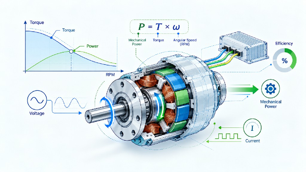
The five headline parameters are connected, but they are not interchangeable. Torque describes the twisting effort at a shaft. Speed describes how fast that shaft rotates. Mechanical power describes the rate of work delivered at the shaft. Voltage helps determine attainable electrical speed and driver requirements. Current, more directly than voltage, is related to torque-producing magnetic force, although the exact relationship depends on motor constants and control method.
Torque: the force that turns the load
Torque is commonly specified in newton-metres (N·m), millinewton-metres (mN·m), or ounce-inches (oz·in). For a simple tangential force applied at radius r, the torque is T = F × r, where force is in newtons and radius is in metres. For example, a tangential force of 20 N at an effective radius of 0.05 m requires 1.0 N·m before accounting for friction and acceleration. The effective radius is the perpendicular moment arm; the formula should not be applied blindly to complex linkage mechanisms.
For a conveyor, torque comes from belt tension differences and roller radius. For a linear actuator, it may come from force, screw lead, and mechanical efficiency. For a vertical axis, gravity can dominate. For a fan, aerodynamic torque typically rises strongly as speed increases. Therefore, “same RPM” does not mean “same torque requirement” across different machines.
RPM: operating speed under load, not just no-load speed
Motor listings may show no-load speed, rated speed, and maximum permissible speed. These values answer different questions. No-load speed is measured at little external shaft load; rated speed is associated with a declared rated operating condition; maximum speed may reflect mechanical, bearing, rotor, or driver-frequency constraints. A motor advertised at 4,000 RPM no-load cannot automatically supply its rated torque at 4,000 RPM.
The crucial question is: At the torque my machine needs, how fast can this motor continuously turn? A speed–torque curve or validated operating-point data is much more useful than one isolated RPM value.
Power: torque multiplied by angular speed
Mechanical shaft power is:
P_mechanical (W) = T (N·m) × ω (rad/s)
Since ω = 2π × RPM / 60, a convenient BLDC motor power calculation is:
P_mechanical (W) = T (N·m) × RPM / 9.5493
Alternatively, when mechanical power and speed are known:
T (N·m) = 9.5493 × P_mechanical (W) / RPM
At 0.30 N·m and 3,000 RPM, the calculated shaft power is 94.25 W. At 0.30 N·m and 1,500 RPM, it is 47.12 W. At zero RPM, shaft power is zero even if the motor is producing holding or stall torque and consuming substantial electrical energy. This last point explains why watts alone cannot describe startup or locked-rotor capability.
Voltage and current: the electrical side of the system
For a DC input bus, the instantaneous electrical input power is approximately P_electrical = V_bus × I_bus. This is input power, not useful shaft output. Motor copper losses, iron losses, friction, windage, and driver losses prevent 100% conversion. If the motor's assumed efficiency at a specific operating point is η_motor, a first estimate is P_motor_input ≈ P_shaft / η_motor. A separate driver efficiency factor may also be necessary for a wall-to-shaft or battery-to-shaft estimate.
Never confuse phase current with DC bus current. They are different quantities in a PWM-controlled three-phase inverter, and some catalogs do not specify which current is being quoted. Likewise, a driver's “15 A peak” phase rating is not the same as a supply that continuously delivers 15 A. Ask for explicit current definitions, operating conditions, and the drive's continuous and peak ratings.
Worked power comparison table
| Shaft torque | Shaft speed | Calculated mechanical power | Interpretation |
|---|---|---|---|
| 0.10 N·m | 1,000 RPM | 10.47 W | Small rotating load |
| 0.10 N·m | 3,000 RPM | 31.42 W | Same torque, three times the power |
| 0.30 N·m | 3,000 RPM | 94.25 W | Useful 24V example operating point |
| 0.50 N·m | 3,000 RPM | 157.08 W | More torque at the same speed |
| 1.00 N·m | 1,500 RPM | 157.08 W | Same power at twice the torque and half the speed |
| 2.00 N·m | 300 RPM | 62.83 W | High-torque, low-speed geared application |
All six figures are calculations from the mechanical-power equation, not measurements of a particular motor. These examples demonstrate why comparing nameplate watts without speed and torque can lead to the wrong product choice.
Rated Torque vs. Peak Torque vs. Stall Torque
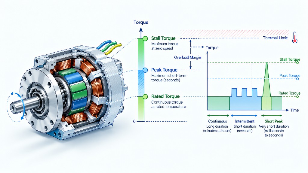
Of all BLDC catalog terms, the torque ratings cause some of the most expensive sizing errors. A user sees a large “maximum torque” number, assumes it is available indefinitely, and chooses a motor too small to handle the real duty cycle. The machine may start successfully during a short test but overheat after an hour or trip its driver during repeated acceleration.
Rated torque generally means the shaft torque supported at specified rated conditions, which may include speed, ambient temperature, mounting, cooling, and a defined duty classification. For continuous applications, verify that the specified rated torque is truly continuous for the chosen mechanical installation. “Rated” is only useful when its measurement conditions are clear.
Peak torque is a short-duration capability above continuous torque. It is constrained by drive current, magnetic saturation, thermal energy accumulation, motor structure, and the permitted time interval. A catalog may say a motor can produce two or three times rated torque briefly, but such ratios must not be assumed across brands or motor types. Require a documented peak-current or overload-time specification before relying on it.
Stall torque is torque at zero shaft speed, but the term is not always defined consistently. It may describe a theoretical voltage-limited locked-rotor condition, a current-limited instantaneous value, or a tested maximum. At standstill, back electromotive force falls to zero while winding heating can be severe. For many BLDC motors, sustained stall without a specified current-limited holding mode is unacceptable. A stall-torque figure does not indicate continuous low-speed holding capability.
| Torque specification | Shaft condition | Time assumption | Correct engineering use |
|---|---|---|---|
| Rated/continuous torque | Defined operating speed and cooling | Sustained under stated conditions | Normal running-load sizing |
| Peak/intermittent torque | Acceleration or temporary overload | Limited by a specified interval | Startup, reversing, momentary disturbances |
| Stall/locked-rotor torque | Zero mechanical speed | Often very short or special test | Analyze jam response; never assume indefinite operation |
A useful procurement question is: “Can the motor continuously deliver X N·m at Y RPM, at our ambient temperature, with our mounting and cooling, while the drive meets our required acceleration peaks?” This question forces the comparison back to a real operating point instead of an attractive but incomplete maximum number.
Calculate Continuous Torque and Acceleration Torque
A practical BLDC motor torque calculation usually combines load torque with the torque required to accelerate rotational inertia. With all quantities referred to the same shaft, a simplified model is:
T_required = T_process + T_friction + T_gravity + J_equivalent × α
Here, J_equivalent is the combined equivalent rotational inertia in kg·m² and α is angular acceleration in rad/s². The signs of gravity and load terms depend on the direction of motion; this simple expression represents a worst-case drive-torque requirement rather than an exact model of every mechanism.
Suppose a rotating assembly has equivalent inertia J = 0.002 kg·m² at the motor shaft and must accelerate from rest to 3,000 RPM in 0.50 s. The final angular speed is 314.16 rad/s, so average angular acceleration is 628.32 rad/s². The inertia torque is 0.002 × 628.32 = 1.26 N·m. If steady resisting torque is 0.30 N·m, the drive must deliver approximately 1.56 N·m during acceleration, before adding additional uncertainty or loss terms.
This illustrates a critical point: a motor adequate for 0.30 N·m steady operation might be grossly undersized for a demanding start profile. A longer acceleration time, smaller equivalent inertia, or a suitable gear ratio can reduce motor-side acceleration torque. Conversely, frequent rapid starts can make peak torque and thermal cycling the dominant selection criteria.
Referring load inertia through a gearbox
For an ideal gear reducer with ratio G = motor speed / output speed, the output inertia reflected to the motor is approximately J_load / G². The motor still accelerates its own rotor inertia, and real transmission inefficiency, backlash, torsional compliance, and load-side dynamics must be considered. The motor torque needed to overcome a load torque at the gearbox output is approximately T_output / (G × η_gear) in forward driving, where η_gear is gearbox efficiency at the relevant load and speed.
For example, assume a 10:1 reducer with 85% efficiency and a desired 2.0 N·m output torque. The required motor torque is 2.0 / (10 × 0.85) = 0.235 N·m, excluding acceleration and other losses. If the output must run at 300 RPM, the motor must turn near 3,000 RPM. This makes a 24V, 3,000 RPM motor potentially relevant—but only after its real continuous torque, gearbox rating, transient duty, and temperature are verified.
For slow automation rollers and compact drive mechanisms, compare this approach with available , because an integrated package may simplify mounting and sourcing.
24V BLDC Motor vs. 48V Brushless DC Motor: Which Should You Choose?
The decision between a 24V BLDC motor and a 48V brushless DC motor is a system decision, not a declaration that one voltage is universally stronger. Both can deliver high efficiency when correctly designed, and either can be produced with different winding characteristics. The correct voltage depends on available electrical infrastructure, required mechanical output, peak currents, acceptable cable size, driver ratings, battery behavior, and electrical safety rules.
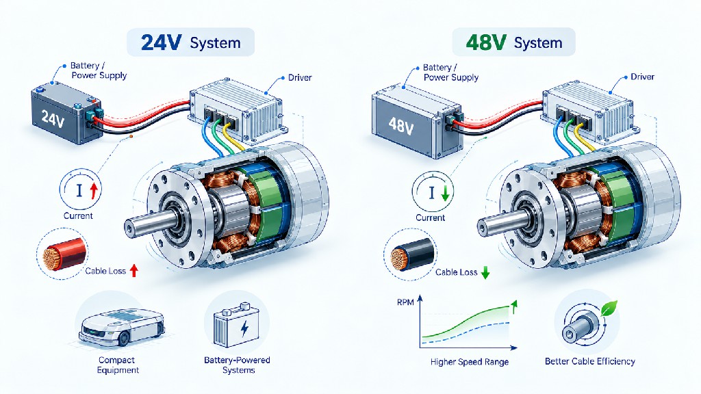
At the same electrical input power, doubling bus voltage roughly halves DC input current, assuming similar conversion efficiency. For example, a system drawing 240 W from the DC bus would ideally need 10 A at 24 V or 5 A at 48 V. With the same cable resistance, conduction heating follows P_loss = I² × R, so halving current can cut that specific resistive loss to one quarter. This is a useful reason to consider 48 V on higher-power, longer-cable machines. It does not mean that a 24V motor can be safely connected to 48 V or that a 48V winding has twice the mechanical torque.
A regulated industrial 24V supply is often convenient for compact equipment because 24V control infrastructure, power supplies, relays, and sensors are common. A nominal 48V bus may be appropriate for larger mobile platforms, conveyor sections with longer cable runs, and systems that need higher power without excessively high DC currents. However, the available supply—and particularly its maximum voltage—must be compared with the absolute limits of both driver and motor insulation-related components.
| Selection factor | 24V system | 48V system |
|---|---|---|
| Typical project appeal | Compact automation and established 24V infrastructure | Higher-power systems and reduced bus current at equivalent input power |
| Example current at 240 W input | 10 A, calculated | 5 A, calculated |
| Cable conduction loss at equal resistance | Higher for the example power | One-quarter of the 24V example if current halves |
| Electrical integration | Often simpler where regulated 24V already exists | Requires appropriate 48V-rated drivers, protection, and power distribution |
| Battery-related caution | Verify fully charged and transient bus voltage | Especially important: a “48V” battery is not always at 48 V |
| Motor selection rule | Choose a winding and driver designed for 24V operation | Choose a winding and driver designed for the actual 48V bus range |
Important: A 48V nominal lithium-ion or lead-acid battery system can exceed 50 V when fully charged. Therefore, a driver labeled 18–50 VDC must not automatically be assumed suitable for a rechargeable “48V” system. Check the complete charge range, braking transients, tolerances, and manufacturer limits. For the available , the published input specification is 18–50 VDC; applications near that upper limit require particular attention.
Voltage alone also cannot determine output speed because winding back-EMF constant, load, current, and control strategy affect attainable RPM. Two motors with the same outer diameter and rated voltage may have entirely different rated speeds or torque constants. When replacing an existing motor, copy the motor part number and winding data—not just the voltage printed on the equipment label.
Motor Constants Explained: Kt, Ke, and Kv
Motor constants connect physical construction to the values used by an engineer during sizing. Understanding them is particularly important when product listings include high RPM or low-voltage winding options. It also helps prevent confusion between a motor capable of turning quickly with little load and one capable of supplying high torque at the target operating speed.
Kt, the torque constant, expresses the relationship between torque-producing current and electromagnetic torque. Its SI unit is N·m/A, sometimes shown as mN·m/A. In an idealized form, T_em = Kt × I_torque, with appropriate treatment of the chosen current reference and no-load or loss torque. Actual shaft torque will be lower than internal electromagnetic torque because of mechanical and other losses. The current may be specified as DC-equivalent, phase RMS, or phase peak depending on the manufacturer's convention.
Ke, the back-electromotive-force constant, describes the voltage generated by the rotating motor per unit angular speed. In SI form it can be written V/(rad/s). Catalogs also use V/kRPM or V per 1,000 RPM; some specify line-to-line RMS voltage while others specify phase or peak voltage. Back EMF increases as the rotor turns faster, leaving less voltage available to force current through winding impedance at high speed.
Kv, the speed constant, is commonly stated in RPM/V. It describes a speed-to-voltage relationship in the defined convention, not torque per volt. As a rule of thumb, a higher Kv winding tends to have lower torque per ampere when geometry and definitions are otherwise comparable; a lower Kv winding tends to have a higher Kt. This is a trade-off in winding design, not a guarantee of better motor efficiency or sustained torque.
For a consistent SI convention in an ideal motor, the numerical relationship between torque and back-EMF constants can be expressed as Kt (N·m/A) = Ke (V/(rad/s)), and Kv (RPM/V) ≈ 9.5493 / Kt. Do not apply this numerical equality indiscriminately to three-phase datasheets. Line-to-line versus phase voltage, RMS versus peak quantities, trapezoidal versus sinusoidal waveforms, and phase-current conventions introduce conversion factors. maxon's gives a useful reference for the meaning of torque, speed, and generator constants.
Example: interpreting a published back-EMF number
The product page reports 3.94 V/kRPM as a back-EMF value. As a simple arithmetic conversion, this equals 0.00394 V/RPM, or about 0.0376 V/(rad/s) under the page's stated voltage basis. Its reciprocal is approximately 254 RPM/V in the same basis. That reciprocal is a constant conversion, not a guarantee that the motor runs at 254 times bus voltage or that its rated load current produces a torque derived directly from 0.0376 N·m/A.
Why the caution? The datasheet excerpt does not fully define the phase or line-voltage and current measurement conventions. The motor's separate rated operating figures are 0.30 N·m at 3,000 RPM, which should be used as the stated mechanical point. To predict load-dependent speed, estimate torque-producing phase current, or tune FOC, request the complete winding resistance, inductance, back-EMF waveform definition, and current convention from the supplier.
| Constant | Common units | What it helps estimate | Main caution |
|---|---|---|---|
| Kt | N·m/A or mN·m/A | Electromagnetic torque per defined current | Verify RMS/peak/phase/DC-equivalent current basis |
| Ke | V/(rad/s) or V/kRPM | Back EMF at a given angular speed | Verify phase vs. line-to-line and RMS vs. peak |
| Kv | RPM/V | Speed-to-voltage relationship | Not a rated loaded-speed guarantee |
| Winding resistance | Ω | Resistive voltage drop and copper heat | Temperature and connection convention matter |
| Winding inductance | H or mH | Current dynamics and PWM/control behavior | Motor electrical frequency affects performance |
A professional supplier should be able to explain which conventions appear on the datasheet. If your application needs robust torque estimation or closed-loop control, ask for those definitions before comparing constants from different manufacturers.
Read the BLDC Motor Speed–Torque Curve Before Buying
The relationship between BLDC motor RPM vs. torque is not described by one universal curve. A motor's winding design, power supply, controller current limit, commutation strategy, heating, and cooling all shape the usable envelope. A speed–torque chart is most valuable when it identifies both the continuous region and the limited-duration region, at a specified voltage and ambient temperature.
A simplified voltage-fed motor model suggests that speed tends to fall as load torque rises because increased current creates a larger resistance drop. But a closed-loop speed controller can increase applied voltage or PWM duty to compensate until it reaches a voltage, current, or thermal limit. The same motor may therefore appear to have nearly constant speed over part of its torque range while still exhibiting a hard boundary at higher load or higher RPM.
Many well-designed brushless drive systems offer a constant-torque region over a defined speed range. In this region, torque capability is largely governed by current and thermal limits. Above a base speed, the voltage available to overcome back EMF becomes restrictive; depending on the motor and control strategy, achievable torque may decline. Field weakening is possible in some sophisticated controllers but should never be assumed for an ordinary BLDC speed driver. Oriental Motor provides published examples of , illustrating why actual performance is tied to the supplied motor-and-driver combination.
Three types of load curve to recognize
Approximately constant torque: Conveyor belts, positive-displacement pumps over certain conditions, and friction-dominated mechanisms can demand similar running torque across a useful speed range. Their required shaft power rises approximately in proportion to speed. They are often limited by starting load, thermal capacity, and the motor's continuous current rating.
Variable torque: Centrifugal fans and pumps commonly exhibit torque requirements that rise roughly with the square of speed near comparable operating conditions; shaft power then scales approximately with the cube of speed. Reducing speed can save significant energy, but this relationship is not exact when static head, system resistance, or operating efficiency changes significantly. The U.S. Department of Energy describes the application and limitations of these .
Inertia-dominated or intermittent load: Pick-and-place arms, mobile robots, indexing tables, and reciprocating mechanisms may have relatively modest steady torque but large brief acceleration peaks. A motor with excellent continuous speed–torque performance can still be unsuitable if its peak current, short-term torque, or braking behavior is inadequate.
For reliable selection, plot the actual requested operating points on top of the candidate motor's continuous and peak envelopes. Include startup, the highest-speed load, the longest steady run, and worst-case ambient temperature. If the supplier cannot provide a curve, ask for test data covering those exact points rather than assuming a general shape applies.
Duty Cycle, Continuous Operation, and Frequent Starts
Duty cycle changes the thermal question. A motor that can manage a short peak may not survive that same load continuously. A machine operating all day needs an adequate continuous torque rating under the installed cooling conditions; a mechanism that runs for two seconds and rests for a minute has a very different heating pattern. Start/stop cycles also create repeated current peaks in the motor windings and driver transistors.
For basic control-system calculations, ON-time duty percentage can be written as D = t_ON / (t_ON + t_OFF) × 100%. For example, 15 seconds ON and 45 seconds OFF corresponds to 25%. This is a useful description of the machine schedule. It is not a reliable direct multiplier for allowable peak torque, because motor temperature is influenced by winding resistance, operating current, electrical losses, heat transfer, and the lengths of the cycles relative to thermal time constants.
Thermal analysis often uses an RMS-equivalent torque approach for applications in which torque-producing current is approximately proportional to torque:
T_RMS = sqrt[(T1² × t1 + T2² × t2 + ...)/(t1 + t2 + ...)]
For an illustration with 0.30 N·m for 20 seconds and 0.90 N·m for 2 seconds, followed by 38 seconds at near-zero commanded torque, the arithmetic RMS is approximately sqrt[(0.30² × 20 + 0.90² × 2)/60] = 0.239 N·m. This figure can assist a preliminary thermal comparison but is not sufficient on its own: core losses, idle current, cooling, speed-dependent losses, acceleration, motor efficiency, and maximum peak duration still matter. A gearmotor's thermal behavior and available lubrication/cooling further complicate the comparison.
| Operating profile | What usually determines suitability | What to ask the supplier |
|---|---|---|
| Continuous 24/7 rotation | Continuous torque, efficiency, thermal equilibrium | Rated curve and temperature-rise conditions |
| Periodic ON/OFF operation | RMS heating plus ON-period peak | Duty test and thermal time assumptions |
| Frequent acceleration | Rotor/load inertia and motor/drive peak current | Peak torque duration and starts-per-hour test |
| Repeated reversing | Peak torque, bus regeneration, gear backlash | Controlled braking, overvoltage strategy, mechanical limits |
| Low-speed loaded running | Current control and cooling near low RPM | Continuous torque at actual low speed |
| Locked rotor or jam | Fault detection and heating protection | Current limiting, locked-rotor trip, safe shutdown |
A standard motor that runs cool on an open bench may behave differently in a sealed cabinet. Ambient temperatures above the datasheet reference, inadequate airflow, a hot mounting plate, or adjacent heat sources reduce thermal headroom. Confirm whether the product rating assumes free air, a heatsinking fixture, a gearbox, a specific drive, or some other mounting condition. Protective electronics matter, but a trip function should be treated as a backup—not as a substitute for continuous-duty sizing.
Hall Sensors vs. Sensorless Control vs. Encoder Feedback
The rotor position strategy determines how readily a BLDC motor can start, how smooth it can run at low speed, and what types of feedback the drive can use. A basic motor may have no sensors, three Hall-effect sensors, or a high-resolution encoder. These are not interchangeable features: they provide different information and require matching electronics.
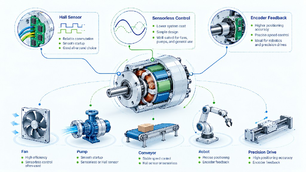
Hall sensors give discrete rotor-position sectors for commutation. In a common three-Hall arrangement, the signals encode six electrical states. They are a practical choice for reliable starting, direction control, and economical closed-loop speed systems. Hall feedback is not, by itself, high-resolution shaft positioning; available mechanical resolution depends on pole-pair count, Hall placement, interpolation, and the drive. For a clear explanation of the switching logic, see Texas Instruments' .
Sensorless control estimates rotor position from measured or modeled electrical quantities. It can reduce motor wiring and the number of components exposed to vibration or heat. However, simple back-EMF-based techniques have weak or no direct rotor-position information at standstill, because generated back EMF is zero at zero speed. Startup under high static load may be more difficult, and sophisticated observer-based controllers require careful tuning. Microchip explains these constraints in its .
Encoder feedback adds a higher-resolution measure of position or velocity. Depending on its construction, an encoder may be incremental or absolute and may use optical or magnetic sensing. A compatible encoder plus suitable servo-capable drive allows far more sophisticated position and velocity control than a basic Hall commutation setup. Encoder resolution alone does not guarantee motion accuracy: backlash, shaft compliance, calibration, control-loop tuning, and mechanical rigidity may dominate the final machine result.
| Feedback approach | Main advantage | Main limitation | Good candidate applications |
|---|---|---|---|
| Hall sensors | Reliable commutation and economical startup feedback | Coarse position information | Conveyors, small AGVs, industrial rollers |
| Sensorless back-EMF estimation | Fewer motor sensors and wires | Startup and very-low-speed limitations | Fans and pumps with manageable starting load |
| High-resolution encoder | Accurate feedback for closed-loop motion | Higher cost, wiring, and control complexity | Robotics, precision transmission, positioning |
An important nuance: a Hall-sensored BLDC motor can be operated with FOC if the controller can use or estimate the required rotor angle, and some advanced sensorless FOC systems operate very well once properly tuned. The choice is therefore a system architecture question, not a declaration that one sensor type is always best.
Choose the Right BLDC Motor Driver and DC Power Supply
A BLDC motor driver is not just a speed knob. It supplies controlled phase currents, performs commutation, applies speed or torque commands, and ideally protects the inverter and motor from abnormal conditions. Driver selection begins by matching the motor's phase configuration and feedback requirements, then confirming operating voltage, continuous and peak current, power dissipation, maximum electrical frequency, acceleration behavior, braking, and interfaces.
At a minimum, check DC bus voltage range, continuous output current, peak output current and allowed duration, Hall/encoder/sensorless support, commutation and control mode, speed range, overcurrent/overvoltage/thermal protection, and ambient operating limits. For a three-phase motor, verify the winding connection and electrical phase order; a Hall-sensored controller must also support the motor's Hall sequence and electrical angle convention.
Texas Instruments' emphasize how voltage, current, architecture, and control methodology affect selection. In practice, the worst-case operating transient is often more important than the nominal power printed on the controller. A fast reversing conveyor may produce regenerative energy, sending current back toward the DC bus and raising voltage if the supply cannot absorb it. A battery may tolerate some returned energy under specific conditions; many ordinary switching supplies cannot. Braking resistors, bus capacitance, controlled deceleration, and driver protection must be engineered together.
An engineering checklist for the driver
| Driver item | What to verify | Why it matters |
|---|---|---|
| Bus range | Minimum, nominal, fully charged, and transient voltage | Prevents undervoltage or overvoltage damage |
| Continuous phase current | Available at the stated ambient and cooling | Sustains required torque without overheating |
| Peak current | Maximum value and allowed time | Supports acceleration and short disturbances |
| Motor commutation | 3-phase wiring, Hall angle/sequence or sensorless mode | Ensures correct startup and rotation |
| Speed capability | Electrical RPM, pole-pair count, and control bandwidth | High-pole-count motors demand faster commutation |
| Braking behavior | Coast, dynamic brake, regeneration, or active stop | Avoids bus voltage spikes and unsafe deceleration |
| Feedback/interface | Analog voltage, PWM, serial, CAN, encoder, or other | Enables machine control and fault reporting |
| Protection and thermal | Current limit, locked rotor, heat sinking, enclosure rating | Supports predictable operation and fault response |
Power supplies must be sized for electrical input rather than rated shaft output alone. A motor producing 100 W at 80% efficiency needs approximately 125 W entering the motor, not 100 W. The upstream DC supply may need to provide more to cover driver losses and other devices. Include starting peaks, cable voltage drop, voltage sag, supply overload response, and capacitor inrush. A power supply rated for the same nominal wattage as the motor is not automatically sufficient.
For a regulated 24V system, the is one potential catalog candidate, because its published listing states an 18–50VDC operating range, a maximum 15 A value, a 400 W headline rating, and Hall or sensorless capability. These headline figures do not by themselves establish the available continuous phase current, thermal rating, or exact compatibility with a given motor. Confirm the manufacturer's detailed driver manual and the motor/driver pairing before procurement. Explore additional if the application needs different control functions or protection.
Real Selection Example: A 24V, 3,000 RPM BLDC Motor for Industrial Automation
Consider a small production-machine roller, light-duty conveyor, or auxiliary rotating assembly that requires approximately 0.30 N·m of continuous motor-shaft torque at 3,000 RPM, with a nominal regulated 24V DC supply. These requirements describe a candidate operating point rather than a guarantee of machine suitability. FRANK HU MOTOR lists a real motor, 57BLDC74-2430, that directly corresponds to this illustrative application. The product page is titled .
Step 1: Read the actual catalog data
| Parameter | Published value for 57BLDC74-2430 |
|---|---|
| Nominal motor voltage | 24 VDC |
| Rated speed | 3,000 RPM |
| No-load speed | 4,000 RPM |
| Rated torque | 0.30 N·m |
| Listed rated power | 100 W |
| Listed rated current | 4.9 A |
| Number of phases | 3 |
| Pole count | 8 |
| Position sensor | Hall; 120° Hall angle noted in listing |
| Back-EMF constant as listed | 3.94 V/kRPM |
| Body dimensions | 57 mm diameter × 74 mm length |
| Shaft diameter | 8 mm |
| Ingress protection stated | IP30 |
These are catalog figures from the named product listing, not independently measured test results. The page contains additional general specifications, and the supplier invites requests for a datasheet and torque curve. Obtain the newest approved documentation before using this motor in a safety-critical, precision, or thermally demanding application.
Step 2: Calculate shaft power from torque and speed
Using the mechanical power formula:
P_shaft = 0.30 × 3000 / 9.5493 = 94.25 W
The exact mathematical result for the stated torque and RPM is about 94 W. The product's headline 100 W rating is close to this result and may reflect rounded or separately defined nominal ratings. We should not rewrite the manufacturer's specification as “94.25 W rated power”; the correct statement is that the published 0.30 N·m / 3,000 RPM operating point corresponds to approximately 94.25 W of mechanical shaft power. This is a useful cross-check, not an allegation that the product listing is wrong.
Step 3: Estimate electrical input, without mixing current definitions
To illustrate the electrical side, suppose the combined motor-and-driver efficiency at that operating point is 80%. This is an assumed example—not a published efficiency claim for this particular model. The power drawn from the 24V DC bus would be approximately:
P_DC_input ≈ 94.25 W / 0.80 = 117.81 W
I_DC_average ≈ 117.81 W / 24 V = 4.91 A
At 85% assumed combined efficiency, the estimated DC input would instead be 94.25 / 0.85 = 110.88 W, or approximately 4.62 A at 24 V. The site's listed 4.9 A rating is numerically close to one of these calculations, but the current's measurement convention and specified operating conditions must be checked before claiming the figures validate each other. Phase current and upstream DC input current are not automatically equal.
Step 4: Choose a driver candidate
The product page links to the . Its advertised features include 18–50VDC input, Hall or sensorless operation, a 15 A maximum headline value, and a 400 W headline rating. These figures indicate a plausible catalog starting point for a nominal 24V BLDC system. They do not establish, without further documents, that the driver supplies 15 A continuously, that any peak current is allowed for a required duration, or that the particular motor/driver Hall sequence is already validated.
The engineering team should confirm five additional items before treating the combination as approved: phase-current rating and heat-sink conditions; required Hall-angle/commutation wiring; adjustable current limits; speed regulation and fault behavior; and response to acceleration, stopping, and an unexpected jam. The product's eight poles correspond to four pole pairs; at 3,000 mechanical RPM the fundamental electrical rotation rate is 3000 × 4 / 60 = 200 Hz. The chosen controller must be capable of commutating at the required electrical speed, with sufficient control bandwidth.
Step 5: Size the supply for the machine, not just for the nameplate
The illustrative operating-point estimate of roughly 4.6–4.9 A average bus current does not include acceleration peaks, other control loads, cable losses, or possible regeneration. A regulated 24V, 8–10 A supply could be a preliminary engineering comparison for a mild-start, single-motor configuration, but it is not a universal purchase recommendation. The actual continuous and transient supply requirements must be established from a measured or modeled current profile and the driver manual. Some supplies shut down during brief overloads; others may fail to absorb returned energy when a loaded mechanism stops.
If the actual machine needs repeated fast acceleration, 0.30 N·m may not be enough. Revisiting the earlier inertia example yields a much higher temporary torque demand. The correct next action would be to alter the motion profile, choose a higher peak-capability motor/driver, or use a gearbox where appropriate. For a higher continuous-torque option in the same broad voltage and speed class, compare the site's , again subject to its actual continuous operating conditions.
Step 6: Make a purchasing decision
This 24V case has a clear conclusion: the 57BLDC74-2430 is a technically relevant candidate for a requirement near 0.30 N·m and 3,000 RPM at the motor shaft, while the BLD-300B is a candidate driver worth checking. What remains unverified from the headline data is the required startup peak, true continuous current and thermal limits, current measurement basis, complete torque curve, and integration behavior. Submit those unknowns alongside the motor part number through and request confirmation before placing a production order.
Application Guide: Fans, Pumps, Conveyors, Robots, and Precision Drives
Fans and blowers: understand speed-dependent load
Fans often look simple because there is no gearbox or heavy mechanical transmission. In reality, blade diameter, air density, duct resistance, starting conditions, and blade geometry strongly influence the load. For similar operation on a fixed centrifugal fan, power commonly varies with approximately the cube of speed. If a fan requires 100 W of shaft power at a specific operating point, a simplified affinity-law estimate at 80% speed is 100 × 0.8³ = 51.2 W. This is a theoretical illustration; actual fan efficiency and system pressure conditions can shift the result.
For many fans that start with little load and run mainly at medium to high speed, sensorless control can be economical. For unusually high starting resistance, highly variable loads, or demanding low-RPM operation, Hall-sensored control may be preferable. Ask for the fan or blower's torque-speed requirement rather than assuming a product listed at the desired unloaded RPM is sufficient.
Pumps: match the hydraulic duty point
Centrifugal pumps have speed-related loads, while positive-displacement pumps often behave more like constant-torque systems for a given pressure differential. A pump selection must incorporate flow, pressure/head, liquid viscosity, pump efficiency, cavitation margins, and startup conditions before the motor can be sized accurately. For example, a pump required to start against high static head may not obey the simplified fan-law estimate used for steady centrifugal operation.
Low-speed sensorless startup under hydraulic pressure can be problematic for some control systems. Hall sensors or a more capable observer/controller can reduce that risk, but the mechanical duty still determines the torque requirement. Include fluid temperature and enclosure exposure when deciding motor protection and bearing arrangements.
Conveyors and industrial rollers: torque at the output shaft
An industrial conveyor is a typical brushless DC motor for industrial automation application. Designers should calculate resistance at the driven roller, factor in gearbox or belt efficiency, and determine both steady and accelerating torque. A fast start with a loaded belt can require far more torque than smooth constant-speed running. Constant-speed control with Hall feedback is a practical starting point for many compact conveyors, whereas synchronized multi-axis systems may need encoder feedback or a more integrated motion controller.
A geared BLDC system is often appropriate when the roller turns slowly but needs substantial torque. Gear ratio reduces output RPM while multiplying torque after losses. Check rated gearbox output torque, radial loads on the output bearing, backlash tolerance, and continuous temperature, not just the electric motor's number of watts. Browse when the application is better described by output torque in N·m at a few tens or hundreds of RPM.
Mobile robots and AGVs: acceleration, battery range, and braking
Robotic platforms and AGVs need careful treatment of wheel traction, vehicle mass, wheel radius, grade, inertia, starts per hour, and battery voltage. An electric drive must accelerate the loaded vehicle and manage slopes; torque demand can also change abruptly when a wheel contacts uneven flooring. A nominal 48V architecture may reduce current at a given input power, but the fully charged battery voltage and regenerative stopping behavior can complicate controller selection. For a wheeled platform, size each drive using the load distribution and traction assumptions for the complete vehicle.
Closed-loop speed feedback helps maintain coordinated motion, while encoder feedback is often useful for odometry and precision control. However, encoder-based wheel odometry still accumulates error from slip and wheel-radius variation. Emergency-stop requirements and brakes must be determined at the machine level. A motor driver stopping electrically is not necessarily a safe holding brake, especially on a ramp.
Precision instruments and robotic joints: control quality matters
Laboratory automation, small robot joints, and high-resolution mechanisms may require exceptionally smooth low-speed rotation, repeatable reversals, and minimal speed ripple. Here, encoder resolution, controller algorithms, cogging torque, transmission backlash, mechanical resonance, and thermal drift can matter more than the nominal wattage. A basic speed-only BLDC controller does not automatically provide a precision servo axis. Where motion demands closed-loop position control, compare the necessary as well as standard .
For OEM teams, custom winding voltage, gear ratio, mounting flange, shaft geometry, connector type, and encoder options can make integration considerably easier. A complete application drawing and motion profile will produce a better quotation and reduce prototype rework.
BLDC Motor Sizing Calculator: Estimate Shaft Power Before You Request a Quote
A lightweight BLDC Motor Sizing Calculator belongs in this article because it converts visitors who know their mechanical requirements into qualified product inquiries. The calculator should ask for four mandatory inputs: target torque (N·m), target speed (RPM), nominal operating voltage (VDC), and ON-time duty cycle (%). Using those values, it should report theoretical shaft power at the specified operating point, a simple cycle-average mechanical-power figure, and an ideal current lower bound for reference.
The main calculation is P_shaft = T × RPM / 9.5493. A cycle-average figure may be calculated as P_shaft × duty_fraction only when the load is zero during the OFF portion and the specified torque/speed remain constant during ON time. The ideal bus-current lower bound is P_shaft / V_nominal; it assumes 100% energy conversion and excludes driver and motor losses. It is therefore not a recommended supply or phase-current rating. The calculator should clearly label every result as theoretical.
| Calculator input | Example entry | What the tool reports |
|---|---|---|
| Target shaft torque | 0.30 N·m | Mechanical torque requested |
| Target shaft speed | 3,000 RPM | Shaft speed requested |
| Nominal bus voltage | 24 V | Context for ideal current lower bound |
| ON-time duty cycle | 60% | Used only for the illustrative cycle-average calculation |
| Instantaneous shaft power | 94.25 W | 0.30 × 3000 / 9.5493 |
| Cycle-average mechanical power | 56.55 W | 94.25 × 0.60, under stated assumptions |
| Ideal minimum bus current while ON | 3.93 A | 94.25 / 24, ignoring all losses |
For website implementation: insert the supplied self-contained BLDC Motor Sizing Calculator HTML component here using an appropriate trusted custom-HTML block or a site template. The component calculates these results in the browser and directs the visitor to the with instructions to supply their operating data. This calculator is a preliminary estimator, not an automated catalog matcher or confirmation of continuous-duty suitability.
Request a motor recommendation: If your application needs a specific speed, continuous torque, peak torque, unusual shaft, or encoder, use your calculator result as the starting point for an engineering inquiry. Include the actual duty cycle, ambient temperature, expected order quantity, and any reference drawings. The sales engineering team can then evaluate a , a , or an for the project.
Common BLDC Motor Selection Mistakes to Avoid
Choosing by wattage alone. A 100W motor at high speed does not provide the same torque as a 100W geared motor at low speed. Always compare the required torque and RPM at the same shaft and make sure the operating point lies within the continuous duty envelope.
Using no-load RPM as the design speed. A motor's unloaded speed is useful background information, not evidence that it can carry the intended load at that speed. Rated speed should be interpreted together with rated torque, supply voltage, and the driver used for testing.
Confusing peak with continuous capability. Peak torque is about short-duration events. If it is necessary every few seconds, the controller and motor may accumulate heat even when a simple duty percentage appears low. Specify the exact acceleration profile and number of cycles per hour.
Assuming higher voltage always means higher torque. Torque primarily depends on permitted torque-producing current and the winding's motor constant. A 48V winding and a 24V winding must each be matched with a suitable controller and operating conditions.
Ignoring driver details. The driver may be the weak link if it cannot supply the peak phase current, read the installed Hall sensors, manage electrical frequency, or handle regenerative braking. Do not substitute a stepper driver or a brushed motor controller for a three-phase BLDC inverter.
Forgetting power-supply behavior. The DC bus can sag on startup and rise during regeneration. A label stating 24 V and enough nominal watts does not guarantee stability. Check the current profile, input capacitors, supply overload behavior, cabling, and allowable overvoltage margin.
Relying on a calculator as final approval. Mechanical power is a necessary sizing calculation, not a complete selection. A useful estimate should lead to a review of torque-speed curves, duty conditions, thermal limits, and control requirements. That review is where an informed supplier adds value.
What to Send FRANK HU MOTOR for a Faster Quotation
The easiest way to shorten the selection and purchasing cycle is to provide a small technical package rather than sending only the question, “Do you have a 24V brushless motor?” The details below help distinguish a simple catalog replacement from a more involved OEM/ODM configuration.
| Information to provide | Useful detail |
|---|---|
| Application | Fan, pump, conveyor, AGV, robot, dispensing system, or other machinery |
| Motion requirements | Target RPM, speed range, continuous torque, peak torque, acceleration time |
| Electrical system | Nominal/minimum/maximum DC voltage, regulated supply or battery |
| Duty profile | ON/OFF times, starts per hour, continuous duration, ambient temperature |
| Mechanical fit | Frame envelope, flange, shaft diameter/length, radial and axial loads |
| Feedback and control | Hall, sensorless, encoder; required interfaces and control modes |
| Transmission | Direct drive or gear ratio, output torque, allowable backlash |
| Environmental requirements | Ingress protection, vibration, noise, temperature, cable routing |
| Procurement information | Prototype quantity, annual demand, target delivery region, drawings |
For engineering-grade specification reviews, ask for the motor's speed–torque curve at the intended supply voltage; continuous and peak conditions; current and back-EMF measurement conventions; electrical connections; mounting drawings; and applicable product-specific compliance documents. A general company statement about certification does not establish that every individual SKU has the same approval scope, so request the relevant documents if compliance is mandatory in your market.
FRANK HU MOTOR offers products across , , and . With a complete requirement sheet, buyers can also discuss shaft geometry, winding choices, cable arrangements, and application-specific motor-and-driver combinations. Use the to begin a technical quotation request.
Frequently Asked Questions About BLDC Motor Selection
How do I choose a BLDC motor for my application?
Determine continuous shaft torque and loaded RPM first, then calculate mechanical power. Identify startup/acceleration peaks and operating duty, decide on nominal and actual DC-bus voltage range, and choose Hall, sensorless, or encoder feedback according to startup and motion-quality needs. Verify the motor's continuous speed–torque envelope and pair it with a compatible driver and power supply. Mechanical mounting, temperature, and gearbox efficiency belong in the final review.
How much torque does a 100W BLDC motor provide?
There is no single answer without speed. At 3,000 RPM, 100 W of mechanical shaft output corresponds to approximately 9.5493 × 100 / 3000 = 0.318 N·m. At 1,000 RPM, the same shaft power corresponds to approximately 0.955 N·m. These are mathematical relationships, not proof that any particular 100W motor can deliver both operating points. Compare real continuous speed–torque data before purchasing.
What is the difference between a 24V and 48V brushless DC motor?
At similar electrical input power, a 48V bus generally requires less DC input current, which can reduce cable losses. However, output torque, speed, and efficiency depend on motor winding design and driver behavior. A nominal 48V battery may exceed 48 V when charged, so the controller's maximum voltage rating is essential. Neither voltage is inherently the correct choice for every machine.
Can a BLDC motor run without Hall sensors?
Yes, if a suitable sensorless driver and startup strategy are used. Back-EMF-based sensorless control is attractive for many fans and pumps, but startup and very low-speed operation require special consideration because back EMF is weak or absent near standstill. Applications needing reliable high-load starts or fine low-speed control may benefit from Hall sensors or more sophisticated feedback.
Does a higher Kv mean a more powerful motor?
No. Kv mainly expresses a motor's speed constant in RPM/V under a defined convention. It is not a power rating. Higher Kv windings often trade torque per ampere for greater speed per volt, but maximum continuous output depends on the complete electromagnetic, mechanical, and thermal design. Compare tested torque-speed operating points rather than Kv in isolation.
How do I calculate BLDC motor power from torque and RPM?
Use P (W) = Torque (N·m) × RPM / 9.5493. For example, 0.50 N·m at 3,000 RPM gives approximately 157.08 W of shaft power. Electrical input power will be higher because the motor and its drive have losses. If shaft speed is zero, mechanical shaft power is zero even though current may produce torque and winding heat.
Is rated torque the same as stall torque?
No. Rated torque is associated with specified normal operating conditions; stall torque is measured or estimated at zero rotation under a particular electrical and time condition. Continuous locked-rotor operation can overheat the motor unless the system is specifically designed and rated for it. Never treat an unspecified stall rating as a continuous holding-torque guarantee.
Do I need a gearbox for a BLDC motor?
Not always. Direct drive is attractive when the available motor speed and torque match the application. A gearbox becomes useful when the machine needs low output speed and substantial output torque, or when a different inertia and mounting arrangement helps overall design. Include ratio, efficiency, backlash, gearhead torque rating, and bearing loads in the calculation.
Can I control the position of an ordinary BLDC motor?
A brushless motor can form part of a position-controlled system, but the driver must support an appropriate closed-loop positioning architecture and usually needs suitable rotor position feedback. Three commutation Hall sensors alone often provide insufficient mechanical position resolution for demanding precision applications. For robotic or machine-tool positioning, evaluate an encoder-equipped brushless servo solution rather than assuming a speed-only controller will provide servo performance.
What should I check before buying a motor and controller together?
Confirm electrical compatibility, continuous and peak current ratings, Hall/encoder conventions, driver fault protections, ambient limits, and the motor's operating torque at target RPM. Ask for a matched connection diagram and a test or performance curve if the application is demanding. Request application-specific documentation for environmental or regulatory compliance where required.
Final BLDC Motor Selection Checklist
A sound BLDC motor selection starts with the machine's real speed, load, and duty cycle—not an attractive advertised RPM or maximum wattage. Calculate the shaft-power requirement, add inertia-related acceleration torque, determine whether the application is constant-torque or variable-torque, and check the motor's continuous speed–torque region. Treat peak and stall torque separately. Then choose the correct 24V or 48V winding and bus architecture, select sensor and control functions, and validate the motor, driver, power supply, and thermal installation as a complete system.
For a practical first step, browse , compare , and consider where output torque and reduction ratio dominate. If you already know your target torque, speed, voltage, and duty cycle, use the BLDC Motor Sizing Calculator on this page to prepare a theoretical power estimate, then for model matching, drawings, driver recommendations, and an application-specific quotation.