The market context explains why this engineering problem deserves attention. According to the , about 542,000 industrial robots were installed worldwide in 2024, and the global operational stock reached approximately 4.664 million units. IFR also reported that annual installations had exceeded 500,000 units for four consecutive years. At the same time, humanoid, collaborative and service robots are pushing actuator design toward lower mass, higher torque density and more integrated joints.
For procurement teams, the practical implication is straightforward: a motor that looks adequate on a catalog page can still produce an actuator that is too hot, too long, too heavy, difficult to route cables through, hard to back-drive, or unstable at the required control bandwidth. Conversely, an oversized motor may solve a peak-torque problem while making the distal links heavier, which increases the torque requirement of every upstream joint.
This guide explains a system-level method for robot joint motor selection, with special attention to three architectures: frameless motors, hollow-shaft servo motors, and integrated servo/actuator solutions. It is intended for engineers and buyers developing industrial robotic arms, collaborative robots, humanoid robots, AGVs with manipulators, exoskeletons, medical/lab automation, inspection robots and other precision motion systems.
FRANK HU MOTOR supplies motion-control components for these kinds of designs, including compact frameless motors. For example, the is specified at 36 VDC, 4 N·m rated torque and 168 rpm, with a 78 mm inner diameter and 109 mm outer diameter. The smaller is rated at 1.77 N·m and 504 rpm with a 35.5 mm inner diameter and 68 mm outer diameter. These examples illustrate an important theme of this article: robot-joint design is a trade-off among torque, speed, diameter, axial length, bore, mass, thermal capability and integration—not a search for the largest power number.
Why Robot Joint Motor Selection Is a System Problem
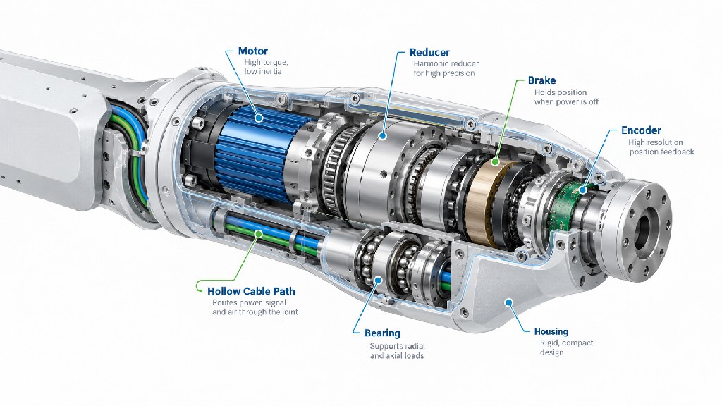
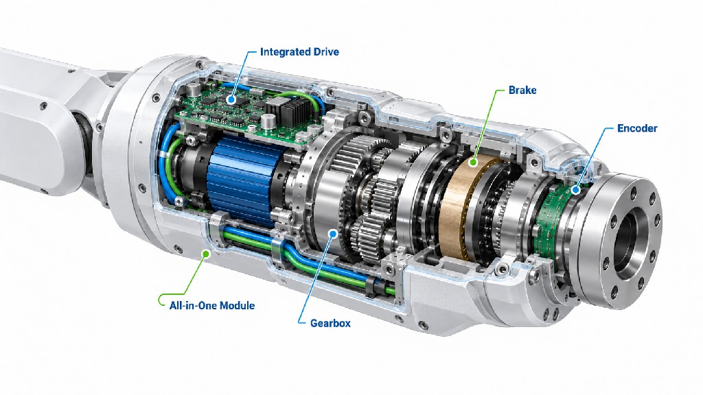
A robot joint converts electrical energy into controlled angular motion, but the motor is only one part of the conversion chain. A typical geared joint contains a brushless permanent-magnet motor, a strain-wave or planetary reducer, one or more bearings, a position sensor, a brake when gravity holding is required, and a structural housing. An integrated joint may also contain the servo drive, temperature sensing and communication electronics.
The selection process should therefore begin at the joint output, not at the motor shaft. Define what the joint must do: maximum output torque, continuous or RMS torque, angular speed, acceleration, travel, duty cycle, allowable temperature, positioning accuracy, stiffness, backdrivability, life and physical envelope. Only then should these requirements be reflected through the reducer to determine motor torque and speed.
A useful first-order relationship is:
T_motor = T_output / (N × η)
where T_motor is required motor torque, T_output is joint output torque, N is the reduction ratio and η is mechanical efficiency. For acceleration, the motor must also accelerate its own inertia and the load inertia reflected through the gearbox.
Reflected load inertia is approximately:
J_reflected = J_load / N²
This squared relationship is one reason high-ratio reducers are attractive in robot joints. A 100:1 reduction theoretically makes the load inertia seen by the motor 1/10,000 of the output-side inertia. Kollmorgen discusses this effect in its , while also warning that gearing efficiency, thermal limits and life must be included in the design.
However, a high ratio is not automatically better. Increasing ratio reduces the motor torque requirement and reflected inertia but raises motor speed for a given joint speed. It may also increase friction, reduce backdrivability, limit output speed, increase transmission compliance effects, and change the way torque sensing or collision detection behaves. For collaborative and humanoid robots, those trade-offs can matter as much as raw torque capacity.
The minimum joint specification before selecting a motor
| Parameter | Why it matters | Typical design question |
|---|---|---|
| Continuous/RMS output torque | Sets thermal loading | What torque must the joint sustain over the duty cycle? |
| Peak output torque | Sets acceleration/disturbance capability | What torque is needed during starts, stops, impacts or short bursts? |
| Maximum joint speed | Determines motor speed after gearing | How fast must the joint rotate under load? |
| Acceleration | Drives transient torque and bus demand | How quickly must the robot reverse or reposition? |
| Joint inertia/load inertia | Affects servo tuning and transient torque | What inertia is reflected to the motor? |
| Radial/axial envelope | Determines motor/reducer geometry | Is diameter or axial length more constrained? |
| Hollow bore | Enables cable, hose or shaft routing | What clear bore is required through the axis? |
| Accuracy/repeatability | Drives encoder and reducer choices | Is the target arc-minutes, arc-seconds or application-level millimeters? |
| Backlash/lost motion | Influences precision and reversals | Can the application tolerate transmission deadband? |
| Backdrivability | Important for safe interaction | Should a human be able to move the joint when unpowered? |
| Thermal environment | Determines continuous torque | Can the housing conduct heat away from the stator? |
| Bus voltage/current | Sets speed-torque capability | What DC bus and peak phase current are available? |
This list is more useful than a motor power target because motor power is derived from torque and speed. Two motors with similar wattage can behave very differently in a low-speed, high-torque robot joint.
Frameless Motors: Maximum Packaging Freedom and Torque Density
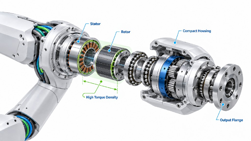
A frameless motor typically consists of a wound stator and a permanent-magnet rotor without the conventional motor housing, bearings, shaft, endbells or connectors. The robot manufacturer integrates those electromagnetic components directly into the actuator structure. Kollmorgen describes this architecture in its , noting that removing redundant mechanical parts enables compact and lightweight motion systems.
This architecture is particularly attractive when the joint designer already needs a precision output bearing, a reducer input interface and a custom housing. Instead of packaging a complete housed servo motor next to those components, the stator can be bonded or clamped into the joint housing and the rotor can be mounted directly to the reducer input or a common rotor carrier.
Why frameless motors fit robotic joints
The first advantage is packaging efficiency. The same structural parts can serve multiple functions. A robot joint housing can locate the stator, conduct heat and support bearings. A rotor carrier can also connect to the reducer. This can reduce redundant shafts, couplings, bearing sets and housings.
The second advantage is torque density. Robot joints often favor relatively large motor diameter and short axial length. For a given electromagnetic loading, increasing effective air-gap radius can strongly increase torque. Kollmorgen summarizes this with the D²L design rule: torque capability scales approximately with the square of diameter and linearly with active axial length. This is why “pancake” torque motors are common in compact joints.
The third advantage is low rotor inertia for the delivered torque. Low inertia helps rapid acceleration and deceleration, although the complete actuator inertia—not only the bare rotor—must be considered.
The fourth advantage is thermal integration. A frameless stator can transfer heat directly into a robot housing if the mechanical interface is designed correctly. This can be much better than trapping a housed motor inside another enclosure. The downside is that the robot designer becomes responsible for the thermal interface, fit, materials, tolerances and assembly process.
The fifth advantage is hollow-axis freedom. Many frameless motors naturally permit a large central opening. This can be used for wiring, pneumatic tubing, cooling lines, optical fibers or a mechanical shaft.
FRANK HU MOTOR frameless examples
The following published products illustrate how frame geometry changes performance. They are not presented as drop-in recommendations for every robot; final selection requires the complete torque-speed curve, thermal conditions and drive data.
| Model | Rated Voltage | Rated Torque | Rated Speed | Inner Diameter | Outer Diameter | Weight |
|---|---|---|---|---|---|---|
| 12 VDC | 0.04 N·m | 792 rpm | 10 mm | 26.3 mm | 0.014 kg | |
| 36 VDC | 1.77 N·m | 504 rpm | 35.5 mm | 68 mm | 0.35 kg | |
| 36 VDC | 4.0 N·m | 168 rpm | 78 mm | 109 mm | 0.58 kg |
The data show why a robot designer should not compare only “N·m per motor.” The 109 mm OD WK10025 offers substantially higher rated torque and a large 78 mm central opening, while the WK6025 trades some torque for higher rated speed and smaller diameter. The tiny WK2205 addresses a completely different scale of mechanism. In an actual robotic actuator, the appropriate choice depends on the reducer ratio, output torque, required bore and thermal boundary conditions.
What the integrator must engineer with a frameless motor
A frameless motor transfers design responsibility from the motor manufacturer to the actuator designer in several areas. The air gap must remain concentric. Rotor magnets must be protected against assembly damage. The stator mounting method must survive thermal cycling. The bearing system must control radial runout and axial position. The encoder must be aligned to the mechanical axis. Cable exits need strain relief. Adhesives, potting compounds and insulating materials must be compatible with the expected temperature range.
This is the reason frameless motors are often the best choice for optimized high-volume robotic joints but may require more mechanical and manufacturing engineering during the first prototype. For teams that need a fast proof of concept, a housed hollow-shaft servo or integrated actuator can sometimes reduce development risk.
Hollow-Shaft Servo Motors: When the Center of the Joint Must Stay Open
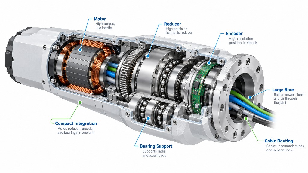
A hollow-shaft servo motor is defined by a through-bore or central passage through the rotating axis. The hollow passage may appear to be a simple mechanical feature, but in robotics it can determine the entire actuator architecture.
Robotic arms frequently need to route motor phase wires, encoder cables, Ethernet/CAN/EtherCAT lines, pneumatic tubes, vacuum lines, coolant or end-effector wiring through multiple joints. External cable loops increase the risk of snagging, fatigue and changing torque loads. A hollow axis lets designers route services through the center of rotation and can simplify the external geometry of the arm.
Harmonic Drive's shows how hollow-shaft gearing is used on primary robot axes and explains that the hollow path can also help reduce axial assembly length. Its current product information also highlights hollow-shaft gear units combined with precision output bearings.
Hollow bore is not a free feature
The required bore should be defined early. A larger bore removes electromagnetic and structural material from the most valuable region of the actuator. It can increase outer diameter for the same torque, reduce bearing options, and complicate the rotor carrier. If the bore is specified larger than necessary, the joint may become heavier for no functional benefit.
A practical specification should therefore state the minimum clear diameter after assembly, not merely the nominal rotor ID. The reducer, encoder, bearing, brake and cable retainers may each reduce the usable passage.
Cable bend radius also matters. A 20 mm bore is not automatically adequate for a 15 mm cable bundle if the bundle must bend sharply immediately after exiting the joint. Connector dimensions may dominate even when the cable itself fits. Many robot designers solve this by using internal connectors, split harnesses or feed-through PCBs.
Hollow-shaft motor checklist
Before specifying a hollow shaft servo motor, answer these questions:
-
What must pass through the joint: electrical cables, pneumatic lines, vacuum, coolant, optical fiber or a mechanical shaft?
-
What is the largest connector or service element that must pass through during assembly?
-
Must the harness be serviceable without removing the reducer?
-
What bend radius is required at both ends of the hollow passage?
-
Does the encoder also need a hollow center?
-
Does the brake reduce the usable bore?
-
Is the reducer itself hollow, and is its bore aligned with the motor bore?
-
Can the output bearing support the required tilting moment while preserving the passage?
A hollow motor becomes valuable when it simplifies the complete robot, not merely because a large hole looks attractive in a CAD model.
FRANK HU MOTOR also supplies hollow-shaft motion products at smaller scales. For example, its combines a hollow shaft with a 2500 CPR incremental encoder for SMT equipment. Although this is not a high-torque robot-joint servo, it demonstrates the same design principle: the center passage can be a functional requirement for air, tooling or wiring rather than a cosmetic feature.
Integrated Servo Motors and Robot Actuators: Faster Development, Different Trade-Offs
An integrated servo solution combines more of the motion system into a single package. Depending on the product, integration can include the motor, encoder, drive electronics, brake, reducer, output bearing, temperature sensing and network interface. In robotics, the term “integrated actuator” often refers to a complete joint module rather than merely a motor with an attached drive.
The strongest advantage is development speed. The supplier has already solved many interface problems: motor-to-reducer alignment, bearing support, encoder mounting, commutation, drive current matching and sometimes thermal protection. A robotics team can focus more quickly on link design, kinematics, control software and application testing.
Integration can also reduce cabling. Harmonic Drive, for example, describes an with an integrated servo drive and CANopen communication using four conductors for CANH, CANL, +24 VDC and 0 VDC. The exact architecture varies by supplier, but the design direction is important: moving drive electronics closer to the joint can reduce central cabinet wiring.
However, integrated actuators create different constraints. They may lock the robot designer into a specific reducer, encoder, drive protocol or mechanical interface. Electronics inside the joint add heat near the motor and gearbox. Serviceability can be more difficult if one component fails. Cost may be higher at the component level even if total engineering cost is lower.
Frameless vs hollow-shaft housed servo vs integrated actuator
| Architecture | Main advantage | Main limitation | Best fit |
|---|---|---|---|
| Frameless motor | Maximum torque-density and packaging freedom | Highest integration responsibility | Custom, optimized robot joints; high-volume designs |
| Hollow-shaft housed servo | Easier mechanical integration with through-routing | More redundant housing/shaft volume | Robots needing central cable/hose passage with moderate customization |
| Integrated servo/actuator | Fastest prototype and lowest interface risk | Less design freedom; thermal/service constraints | Rapid development, modular robots, lower engineering bandwidth |
| Direct-drive torque motor | No reducer backlash/compliance; excellent smoothness | Requires high motor torque and often larger diameter | Gimbals, precision axes, special low-speed joints |
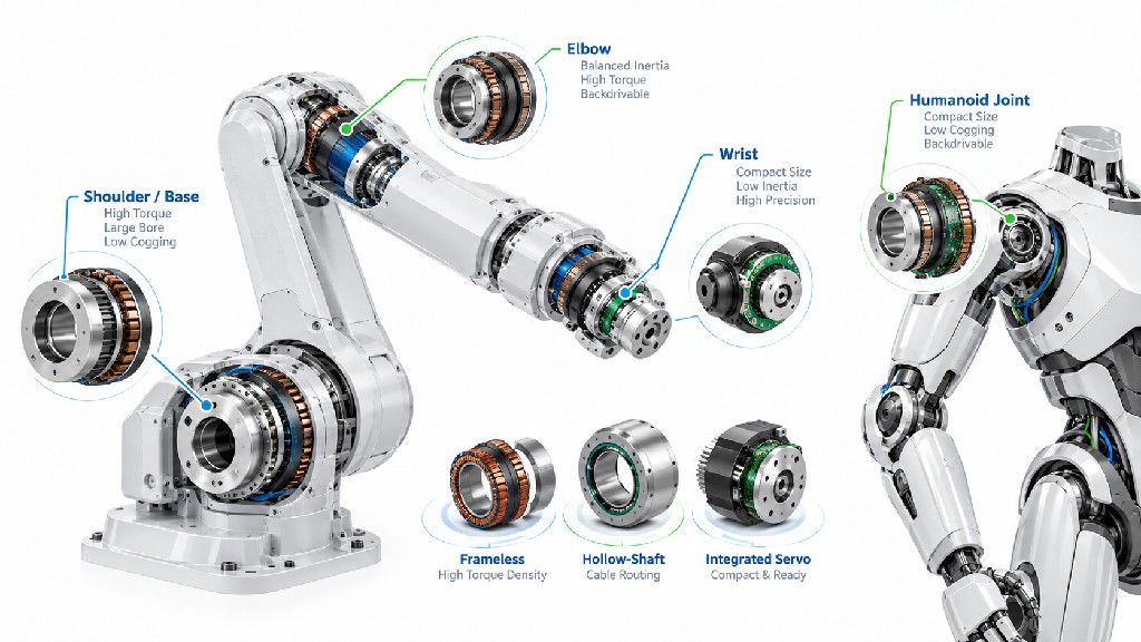
There is no universal winner. A humanoid hip may prioritize torque density and structural integration, favoring a frameless motor with a compact reducer. A wrist may prioritize a large hollow bore and low mass. A research robot may prioritize development speed and choose an integrated actuator even if it is not the lightest possible solution.
Torque: Continuous, Peak and RMS Are Three Different Numbers
Torque is the most misunderstood specification in robotic arm motor selection. A robot joint rarely operates at one constant load. It accelerates, holds against gravity, decelerates, changes direction and may experience external contact. The motor must survive both short peaks and long-term heating.
Peak torque determines whether the motor can produce a short burst for acceleration, disturbance rejection or a transient load. It is usually limited by drive current, motor magnetic design and allowable duration.
Continuous torque is the torque the motor can sustain under specified thermal conditions without exceeding its temperature limit. This rating depends heavily on how the motor is cooled. A frameless motor mounted into a large aluminum joint housing may sustain more continuous torque than the same electromagnetic core in a poor thermal environment.
RMS torque converts a variable duty cycle into an equivalent heating load. For a cycle containing several torque levels:
T_RMS = sqrt[(T1²t1 + T2²t2 + ... + Tn²tn) / (t1 + t2 + ... + tn)]
The selected motor should normally have a continuous thermal capability above the calculated RMS requirement with appropriate engineering margin, while its peak capability must exceed the maximum transient torque.
Example RMS calculation
Consider a joint cycle of 10 seconds:
-
2 s accelerating at 3.0 N·m motor torque
-
5 s moving/holding at 1.2 N·m
-
2 s decelerating at 2.5 N·m
-
1 s lightly loaded at 0.3 N·m
The RMS torque is approximately:
T_RMS = sqrt[(3.0²×2 + 1.2²×5 + 2.5²×2 + 0.3²×1) / 10] ≈ 1.94 N·m
A motor with a 3 N·m peak rating but only 1.2 N·m continuous capability would likely be thermally undersized for this cycle. This is why selecting from peak torque alone can produce a robot that works for a few minutes and then overheats.
Output torque after a reducer
If a motor produces 1.5 N·m and drives an 80:1 reducer with 70% efficiency at the relevant operating point, a simplified output estimate is:
T_output ≈ 1.5 × 80 × 0.70 = 84 N·m
But the 70% efficiency must not be treated as a universal value. Gear efficiency varies with ratio, speed, load, lubricant and temperature. Harmonic Drive's published explicitly shows that efficiency depends on these conditions. Use the actual reducer supplier's curves for final sizing.
Speed, Gear Ratio and Backdrivability
A joint's maximum angular speed sets the motor speed after reduction. If the output must reach 60 rpm and the reducer ratio is 80:1, the motor must reach approximately 4,800 rpm, ignoring compliance and other effects. That may immediately exclude a low-speed torque motor winding even if its torque looks attractive.
This is where bus voltage becomes important. At higher speed, motor back-EMF rises. The drive needs sufficient voltage headroom to force current into the winding. A motor can have adequate low-speed torque yet fail to produce the required torque at high rpm because the available DC bus voltage is too low.
For battery-powered humanoid robots, the voltage decision also affects conductor current, copper losses, drive design and battery architecture. A higher bus voltage can reduce current for a given electrical power, but it changes insulation, switching and safety requirements.
Choosing reducer ratio
The ratio should be selected by balancing at least five effects:
-
Motor torque requirement falls as ratio increases.
-
Motor speed requirement rises as ratio increases.
-
Reflected load inertia falls with the square of ratio.
-
Mechanical losses and friction influence efficiency and backdrivability.
-
Transmission stiffness and control behavior affect force/torque response.
Strain-wave gearing is popular because it provides high reduction in a compact package and can achieve zero backlash at the gear teeth. describes the three main elements—wave generator, flexspline and circular spline—and the mechanism's compact high-ratio characteristics. Its CSF-2XH miniature series, for example, offers ratios from 30:1 to 100:1 for compact robotics and semiconductor applications.
Planetary gearboxes are also common, particularly where efficiency, robustness and backdrivability are important. Harmonic Drive notes that a single planetary stage can reach ratios up to about 10:1, with higher ratios generally requiring multiple stages. Cycloidal reducers are another important option for high-load robotic axes.
Backdrivability is a system property
Do not label a joint “backdrivable” based only on motor type. Backdrivability depends on reducer ratio, reducer friction, seal drag, bearing preload, motor cogging, electromagnetic damping and control strategy. A low-cogging frameless motor behind a very high-friction reducer may still be difficult to move manually.
For cobots, exoskeletons and humanoids, low friction can improve force control and physical interaction. However, high backdrivability also means a gravity-loaded joint may fall when power is removed unless a brake or counterbalance is used. Safety analysis must therefore include the complete mechanical system.
Inertia and Dynamic Response: Why a Lightweight Joint Can Outperform a Bigger Motor
Robot performance is strongly affected by inertia. Every gram added near the end of an arm must be accelerated by upstream joints. This creates a cascading effect: a heavy wrist increases elbow torque; a heavier elbow actuator increases shoulder torque; the larger shoulder actuator then increases base requirements.
This is one reason torque density is so valuable. It is not simply a marketing ratio. Lower actuator mass can reduce total robot energy consumption and improve acceleration throughout the kinematic chain.
At the motor level, servo tuning is influenced by the ratio between reflected load inertia and motor rotor inertia. There is no single universal “correct” inertia ratio for all modern servo systems, but extremely large mismatch can make high-bandwidth control more difficult. Gear reduction can improve the apparent ratio because load inertia is divided by N² when reflected to the motor.
Basic acceleration torque
Acceleration torque is:
T_acc = J_total × α
where J_total is the inertia seen by the motor and α is angular acceleration in rad/s². The total motor torque also includes gravity, friction and process/external loads:
T_motor,total = T_acc + T_gravity + T_friction + T_external
For a horizontal joint, gravity torque changes with arm angle. A simple single-link approximation is:
T_gravity = m × g × r × sin(θ)
where m is effective mass, g is gravitational acceleration, r is distance from the joint to the mass center and θ is the angle relative to the gravity vector. Multi-link robots require a full dynamic model because downstream links and payloads contribute to upstream joint torque.
Practical rule: size from the motion profile, not static payload
A robot advertised to carry 10 kg does not tell you the motor torque. A 10 kg payload held 0.1 m from the joint creates a very different gravity moment from the same payload 0.8 m away. Acceleration can add another large torque component. The correct input is the robot's kinematic geometry and motion profile, preferably evaluated across worst-case poses.
Encoder Resolution, Accuracy and Control Bandwidth
The encoder closes the position and velocity loop. In a geared robot joint, engineers must decide whether to measure motor position, output position or both.
A motor-side encoder is useful for commutation and high-bandwidth motor control. With a reducer, its apparent output resolution is multiplied by the ratio. For example, a 20-bit motor encoder provides 1,048,576 counts per motor revolution. Behind a 100:1 reducer, the theoretical count granularity at the output becomes extremely fine.
But theoretical resolution is not the same as absolute output accuracy. Gear transmission error, torsional compliance, bearing deflection, structural flex, encoder eccentricity and calibration all contribute to actual joint accuracy.
An output-side encoder can directly measure the joint after the reducer, allowing the controller to compensate for some transmission errors. Dual-encoder architectures—one on the motor and one on the output—are increasingly useful in precision robots, force-controlled systems and humanoid joints.
Incremental vs absolute feedback
Incremental encoders are cost-effective and can provide excellent resolution, but the system may require homing after power-up. Absolute encoders retain or report position without a conventional homing cycle, which is valuable for multi-axis robots that must recover quickly after power loss.
When evaluating encoder specifications, consider:
-
single-turn versus multi-turn absolute position;
-
bits per revolution or counts per revolution;
-
absolute accuracy, not only resolution;
-
repeatability;
-
maximum electrical/mechanical speed;
-
interface latency;
-
temperature drift;
-
immunity to magnetic fields and EMI;
-
hollow-bore requirement;
-
safety-rated feedback requirements, if applicable.
A high-resolution encoder cannot correct a mechanically soft joint by itself. Encoder choice, reducer stiffness, bearing stiffness and structural design must be treated together.
Cogging Torque, Torque Ripple and Smooth Low-Speed Motion
Cogging torque is the torque variation caused by the interaction between permanent magnets and stator slot geometry even when no current is applied. Torque ripple also includes electromagnetic effects under powered operation. In high-ratio geared systems, some motor ripple may be attenuated or transformed by the reducer, but it can still affect low-speed smoothness, force control and acoustic behavior.
For a humanoid robot joint or collaborative arm, smooth torque production can be more important than maximum no-load speed. Applications involving hand guiding, impedance control or precise force interaction benefit from low cogging, low friction and accurate current control.
Motor geometry influences cogging. Slot/pole combinations, skewing, magnet shape, winding distribution and control algorithms can all be used to reduce ripple. Slotless motors can offer extremely smooth motion but may trade electromagnetic loading and thermal characteristics against slotted designs. There is no architecture that is best for every joint.
The correct procurement question is not simply “Is cogging low?” Ask for a torque ripple or cogging specification under defined conditions, and evaluate the complete actuator at the output. If force control is important, measure output torque versus commanded current across position and speed.
Thermal Design: Continuous Torque Is Really a Heat-Rejection Specification
Motor copper loss is approximately proportional to current squared:
P_copper = I²R
As winding temperature rises, copper resistance also rises, increasing loss for the same current. Iron loss, eddy-current loss, bearing loss and drive loss add more heat. In an integrated actuator, the reducer and servo electronics may share the same compact thermal environment.
This is why continuous torque cannot be separated from mounting conditions. A frameless stator bonded into a thick aluminum housing with a large conductive path can behave very differently from the same motor mounted through a thin plastic or poorly fitted interface.
Build a thermal path intentionally
A robust robot-joint thermal design answers four questions:
-
Where is heat generated?
-
Through what materials and interfaces does it travel?
-
Where is the final heat sink—robot structure, ambient air or liquid cooling?
-
What winding, magnet, bearing, lubricant, encoder and electronics temperatures are allowable?
The gearbox can be the limiting component even when the motor winding is safe. Kollmorgen's robotics guidance gives an example where nearby gearing temperature limits constrain allowable motor winding temperature. Reducer lubricant life is also temperature-dependent.
For high-duty-cycle joints, consider temperature sensors in or near the winding and use drive firmware to implement thermal protection. For humanoid robots, remember that sealed cosmetic covers can dramatically reduce convection compared with an open laboratory prototype.
Thermal validation should use the real duty cycle
Bench tests should reproduce the actual RMS torque, speed profile and ambient temperature. A “no-load spin” test tells little about a joint that spends most of its life holding gravity torque. Likewise, a static holding test does not capture iron and switching losses at high speed.
When comparing suppliers, request torque-speed curves and continuous ratings under clearly stated thermal assumptions. FRANK HU MOTOR product pages encourage customers to request datasheets, 3D STEP files and torque curves for frameless models; these are exactly the documents required before freezing an actuator design.
Bearings, Structural Loads and the Output Interface
The motor produces torque, but the robot joint also carries radial force, axial force and overturning moment. Those loads should normally be handled by a dedicated bearing system rather than by assuming the motor rotor can serve as the structural joint bearing.
Cross-roller bearings are common in compact robotic joints because they can support radial, axial and moment loads in a compact envelope. Some strain-wave gear units integrate an output bearing. Harmonic Drive's robot application handbook specifically notes the value of strong cross-roller bearings on primary robot axes where significant tilting moments occur.
Bearing design affects motor air gap
In a frameless motor, bearing runout directly influences rotor-stator concentricity. If the air gap becomes too small on one side, the rotor may rub the stator or magnetic forces may become uneven. Therefore bearing tolerance, housing stiffness, machining datums and assembly sequence are part of motor integration.
The output bearing also influences encoder accuracy. An encoder mounted on a flexible or poorly supported structure can report apparent position error as the joint deflects under load.
Do not let the reducer become the accidental structural bearing
Some reducers are designed to support output loads; others are not. Read the reducer's allowable moment and bearing-load data. If the reducer requires an external bearing, design it explicitly. A robot joint that meets torque requirements but fails bearing life is still an undersized actuator.
Direct Drive Torque Motors: When Eliminating the Reducer Is Worth It
A direct-drive torque motor connects the motor directly to the joint load without a speed reducer. This eliminates gearbox backlash, transmission error and gear compliance. It can produce extremely smooth, quiet motion and excellent force transparency.
The price is motor size and current. Without torque multiplication, the motor must generate the full output torque directly. For a joint requiring 80 N·m continuous output, a direct-drive motor must produce approximately 80 N·m itself, while a geared motor may need only a small fraction of that torque.
Direct drive is therefore attractive for applications where precision, smoothness, low maintenance or backdrivability outweigh diameter and mass constraints. Examples can include gimbals, rotary tables, certain medical systems, inspection axes and specialized robot joints.
A large-diameter frameless torque motor is often the natural implementation. The large radius increases torque capability, and the central bore can remain available for routing. The joint housing then provides the bearings and structural support.
Direct drive vs geared joint
| Design factor | Direct drive | Geared joint |
|---|---|---|
| Backlash | Essentially none from gearing | Depends on reducer; strain-wave can provide zero gear-tooth backlash |
| Mechanical compliance | Low transmission compliance | Reducer adds torsional compliance |
| Motor torque required | High | Reduced by gear ratio |
| Motor speed | Low, near joint speed | Higher by gear ratio |
| Diameter | Often larger | Can be smaller motor with reducer |
| Backdrivability | Potentially excellent | Depends strongly on reducer/friction |
| Maintenance | Fewer transmission components | Reducer lubrication/life may matter |
| Cost/weight | Can rise quickly at high torque | Often efficient for high output torque |
A Practical Motor Selection Workflow for Robotic Arms and Humanoid Joints
The following workflow can be used during concept design and supplier discussions.
1. Define the joint output requirement
Start with output torque and speed across the complete motion cycle. Include gravity, payload, link inertia, acceleration, friction and external process forces. Calculate both peak and RMS torque.
For humanoids, evaluate dynamic poses rather than only standing loads. Knee, hip and ankle joints can see large transient loads during walking, stair climbing, squatting or recovery from disturbance.
2. Define the mechanical envelope
Specify maximum outer diameter, maximum axial length and minimum hollow bore. Do not say only “compact.” A supplier needs dimensions. Also define total actuator mass target because mass influences upstream joints.
3. Choose the architecture
Use a frameless motor when packaging optimization and torque density justify custom integration. Use a hollow-shaft housed servo when through-routing is essential but you want to reduce motor-integration work. Use an integrated actuator when development speed and validated interfaces matter more than maximum design freedom. Consider direct drive when gearbox effects are unacceptable.
4. Select a preliminary reducer ratio
Convert output speed to motor speed and output torque to motor torque. Check reducer efficiency using supplier data. Calculate reflected inertia. Repeat for several ratios rather than accepting the first value.
5. Check the motor torque-speed curve at the actual bus voltage
A rated torque number without speed is incomplete. Confirm continuous and peak operating points on the torque-speed curve. Make sure the drive can supply the required peak and continuous current.
6. Verify thermal performance
Calculate RMS torque and estimate losses. Define ambient temperature, housing material and heat-sink conditions. If the motor is frameless, provide the supplier with the intended mounting geometry because it can change continuous performance.
7. Select feedback
Choose motor-side encoder resolution and absolute/incremental type. Decide whether output-side feedback is needed. Consider encoder bore, interface, latency and environmental requirements.
8. Verify reducer precision and backdrivability
Check backlash or lost motion, torsional stiffness, transmission error, starting torque and backdriving torque. Harmonic Drive describes strain-wave gearing as zero backlash at the gear teeth, but actual actuator behavior still includes elastic windup, bearings, couplings and other interfaces.
9. Design bearings and mechanical interfaces
Verify radial, axial and moment loads. Check bearing life and stiffness. Confirm rotor/stator concentricity tolerance and assembly method for frameless designs.
10. Validate the complete actuator
Prototype testing should include thermal soak, repeated acceleration, holding torque, emergency stop, backdrive force, output positioning error, torque ripple, acoustic noise and long-duration cycling. Validate the joint, not only the motor.
Worked Selection Example: A Compact Robotic Arm Elbow Joint
Consider a hypothetical elbow joint for a collaborative robotic arm. This example is simplified for education; a production robot requires full dynamic modeling and safety validation.
Assume the following output requirements:
| Requirement | Value |
|---|---|
| Peak joint torque | 75 N·m |
| RMS joint torque over cycle | 28 N·m |
| Maximum joint speed | 60 rpm |
| Maximum actuator OD | 110 mm |
| Maximum actuator length | 95 mm |
| Required clear bore | 35 mm |
| Target supply | 48 VDC bus |
Suppose an 80:1 strain-wave reducer is being evaluated. Assume 70% efficiency for a preliminary worst-case calculation; the final value must come from the selected reducer's efficiency map.
Peak motor torque estimate:
T_peak,motor = 75 / (80 × 0.70) ≈ 1.34 N·m
RMS motor torque estimate:
T_RMS,motor = 28 / (80 × 0.70) ≈ 0.50 N·m
Maximum motor speed:
n_motor = 60 × 80 = 4,800 rpm
Immediately, the selection problem becomes clearer. The motor needs enough short-term torque for approximately 1.34 N·m, continuous thermal capability above the RMS requirement with margin, and the ability to deliver the required torque at up to 4,800 rpm from the available bus voltage. A motor optimized for 168 rpm is obviously not interchangeable with a high-speed winding simply because it can produce several N·m at low speed.
Now consider the 35 mm clear-bore requirement. The motor rotor bore must likely be larger than 35 mm because the reducer, encoder carrier or cable guides may intrude into the passage. This may favor a larger-diameter frameless design or a purpose-built hollow actuator.
Next, check inertia. If the output load inertia at the joint is 0.8 kg·m², the ideal reflected inertia through an 80:1 ratio is:
J_reflected = 0.8 / 80² = 0.000125 kg·m²
The motor rotor inertia, reducer input inertia and other rotating parts must be added to this value. Servo simulation can then evaluate acceleration current and control bandwidth.
Finally, evaluate thermal behavior. The elbow may spend long periods supporting gravity even when it is not moving. That means low-speed or zero-speed copper heating can dominate. The housing should conduct stator heat into the robot link, and a temperature sensor should protect the winding.
This example demonstrates why “75 N·m robot joint” is not a sufficient motor specification. The motor itself may only need around 1–2 N·m because of gearing, but it must provide that torque at the correct speed, voltage, duty cycle and physical geometry.
Selection Priorities by Robot Type
Different robots emphasize different actuator properties.
| Robot/application | Highest priorities | Common architecture direction |
|---|---|---|
| Industrial 6-axis robot | stiffness, repeatability, life, payload | servo + precision reducer; hollow primary axes |
| Collaborative robot | low mass, force control, low friction, safety | frameless + strain-wave; dual feedback increasingly useful |
| Humanoid robot | torque density, mass, efficiency, compactness | frameless/hollow integrated joint modules |
| Exoskeleton | backdrivability, low mass, quiet operation | compact frameless or integrated actuator |
| Surgical/medical robot | precision, smoothness, cleanliness | low-cogging frameless/direct drive or precision geared servo |
| AGV manipulator | robustness, efficiency, serviceability | geared servo or integrated actuator |
| Robot wrist/end effector | low mass, small diameter, cable routing | hollow frameless or compact integrated actuator |
The rapidly growing robot population reinforces the need for scalable actuator architectures. IFR reported that Asia accounted for 74% of new industrial robot deployments in 2024, with China alone representing 54% of global installations. For suppliers and OEMs, this means robot-joint components increasingly need not only prototype performance but also manufacturability, supply continuity and consistent quality at volume.
Safety and Compliance Considerations
Motor sizing is not a substitute for robot safety engineering. Industrial robot manufacturers should consider the applicable machinery and robot safety requirements for the target market. specifies safety requirements for industrial robots, while addresses industrial robot applications and robot cells.
For collaborative applications, torque, speed, stopping behavior, brakes, sensing and control architecture may all affect risk reduction. A motor capable of high peak torque can improve dynamic performance, but the control system must ensure that torque is managed safely. Brakes should be sized for the actual gravity load and failure conditions, not merely motor rated torque.
Electrical design should also address insulation, grounding, EMC, overcurrent, overtemperature and safe power removal. If the joint contains an integrated drive, the thermal and electrical safety analysis must include the electronics inside the actuator.
FRANK HU MOTOR states that its product portfolio supports CE, RoHS and ISO9001-related quality/compliance requirements, but a finished robot OEM remains responsible for validating the complete machine against the standards and regulations applicable to its product and market.
What to Send a Motor Supplier for a Useful Quotation
A good RFQ dramatically improves the quality of motor recommendations. Instead of asking for “a 500 W robot motor,” send the following information:
| RFQ item | Recommended information |
|---|---|
| Application | cobot elbow, humanoid knee, wrist, AGV arm, etc. |
| Peak output torque | N·m and duration |
| RMS/continuous output torque | N·m and duty cycle |
| Maximum joint speed | rpm or °/s |
| Reducer | type, ratio, efficiency if already selected |
| Motor bus voltage | 24/36/48/72 VDC or other |
| Peak/continuous current limits | drive capability |
| Outer diameter limit | mm |
| Axial length limit | mm |
| Minimum hollow bore | mm after assembly |
| Encoder | incremental/absolute, resolution, interface |
| Brake | required holding torque and voltage |
| Environment | ambient temperature, IP target, shock/vibration |
| Thermal interface | housing material, cooling method |
| Quantity | prototype, pilot and annual volume |
| Deliverables | torque curve, CAD/STEP, drawing, FEA/thermal data, samples |
For a custom frameless motor, also provide the proposed stator and rotor mounting method, allowable air gap, bearing arrangement and housing material. If a reducer is already selected, share its input interface and permissible motor geometry.
FRANK HU MOTOR supports custom shafts, windings and OEM/ODM configurations across its motion-control portfolio. For robot-joint projects, the most productive supplier discussion begins with the complete actuator requirement so the electromagnetic design can be matched to the mechanical and thermal system.
Common Robot Joint Motor Selection Mistakes
Selecting by rated power alone
Watts do not tell you whether the motor can deliver the required low-speed torque, peak acceleration torque or high-speed operating point. Always work from torque-speed requirements.
Using peak torque as continuous torque
Peak torque may be available for seconds, not indefinitely. Use RMS torque and thermal limits for continuous sizing.
Ignoring reducer efficiency
Output torque is not motor torque multiplied by ratio with 100% efficiency. Use efficiency data at the actual speed, load and temperature.
Specifying the bore too late
A late hollow-bore requirement can force a complete redesign of the motor, encoder, reducer and bearings. Define routing needs during architecture selection.
Treating encoder resolution as joint accuracy
Resolution is only one contributor. Reducer transmission error, stiffness, bearing deflection and calibration also matter.
Forgetting the thermal path
A frameless motor does not have a universal continuous torque independent of installation. Housing contact and cooling are part of the motor system.
Oversizing distal joints
Extra wrist mass propagates into larger elbow and shoulder requirements. Optimize mass at the end of the arm aggressively.
Assuming zero backlash means zero compliance
Strain-wave gears can provide zero backlash at the gear teeth, but torsional elastic deformation still exists. Check torsional stiffness and lost-motion specifications.
Ignoring backdriving torque
For human-interactive robots, starting friction and reducer backdriving torque can dominate perceived joint transparency.
Freezing the motor before the reducer and bearing layout
The best robot joint is usually co-designed. Motor diameter, reducer size, bearing location, encoder placement and cable routing should evolve together.
Procurement Comparison: What Matters Beyond the Datasheet
For B2B buyers, motor performance is only part of supplier selection. Robotics programs move from prototypes to pilot builds and then to volume production, and the requirements change at each stage.
During prototyping, fast access to samples, CAD models, torque curves and engineering communication may be more important than the final unit price. During pilot production, dimensional consistency, encoder calibration, winding consistency and traceability become more important. At volume, supply continuity, process control, customization stability and change management become critical.
Ask whether the supplier can maintain magnet grade, lamination material, winding process, sensor configuration and mechanical tolerances across batches. A seemingly minor unannounced change in rotor magnet material or encoder alignment can force servo retuning.
For custom frameless motors, define acceptance criteria for phase resistance, inductance, back-EMF constant, torque constant, cogging torque, insulation resistance, dielectric strength, sensor alignment and dimensional runout. For integrated actuators, add firmware version, communication behavior and fault handling to the controlled specification.
FAQ: Robot Joint Motors
What motor is best for a robotic arm joint?
There is no single best motor. Brushless permanent-magnet servo motors are common because they offer high efficiency, controllability and power density. Frameless versions are preferred when the joint needs maximum packaging freedom; hollow-shaft versions are useful when cables or hoses must pass through the axis; integrated actuators reduce development time.
Why are frameless motors popular in robot joints?
They remove redundant housing, bearings and shaft components and can be integrated directly into the robot structure. This allows the designer to optimize diameter, axial length, hollow bore, heat transfer and reducer integration. Kollmorgen specifically identifies robot and cobot joints as major frameless-motor applications.
Is a frameless motor the same as a torque motor?
Not necessarily. “Frameless” describes the mechanical packaging, while “torque motor” generally describes a motor optimized for high torque at relatively low speed, often with large diameter and short axial length. Many torque motors are frameless, but frameless motors can also be designed for higher speed.
How much peak torque should a robot joint motor have?
It depends on the acceleration profile, payload, link geometry, reducer ratio, efficiency and external disturbance requirements. Calculate the worst-case transient motor torque and then apply an engineering margin appropriate to the application. Do not use a generic multiplier without checking the drive current and thermal limits.
How do I calculate continuous motor torque for a robot?
Calculate torque across the full duty cycle, reflect output loads through the reducer, and compute RMS motor torque. Then compare that value with the motor's continuous torque under your actual cooling conditions.
What gear ratio is common in robot joints?
There is no universal ratio. Compact strain-wave robot joints often use relatively high ratios, and commercial strain-wave products commonly span ranges such as 30:1 to 100:1 or higher. The optimum ratio depends on motor speed, torque, backdrivability and dynamic requirements.
Why is hollow shaft important in a robotic arm?
It allows cables, air tubes, vacuum lines and other services to pass through the axis of rotation, reducing external cable loops and simplifying packaging. The required clear bore should be specified after accounting for the reducer, encoder, bearing and connectors.
Do I need an absolute encoder?
Absolute feedback is valuable when the robot should know its joint position immediately after power-up without a homing routine. Whether it is necessary depends on the robot architecture, safety concept, cost target and recovery requirements.
Does a high-resolution encoder guarantee high positioning accuracy?
No. Encoder resolution only describes measurement granularity. Actual joint accuracy also depends on encoder accuracy, reducer transmission error, torsional stiffness, bearing deflection, structural flex and calibration.
Are direct-drive motors better than geared motors?
Direct drive eliminates gearbox backlash and transmission compliance and can provide excellent smoothness and backdrivability. However, the motor must generate full joint torque, often increasing diameter, mass and current. Geared joints are usually more compact for high output torque.
What information should I provide for a custom robot joint motor?
Provide peak and RMS torque, maximum motor/joint speed, bus voltage, reducer ratio, OD and length limits, required hollow bore, encoder type, brake requirements, thermal conditions, bearing concept, expected quantity and desired CAD/torque-curve deliverables.
Final Selection Checklist
Before approving a robot joint motor, confirm all of the following:
-
Peak motor torque is available at the required motor speed and bus voltage.
-
RMS torque is below the continuous thermal capability with realistic cooling.
-
Maximum motor speed is within mechanical and electrical limits.
-
Reducer efficiency is based on supplier data, not an assumed constant.
-
Reflected inertia and rotor inertia support the desired dynamic response.
-
Outer diameter, axial length and clear bore all fit the complete actuator.
-
Encoder resolution, accuracy and interface match the control requirement.
-
Cogging and torque ripple are acceptable for low-speed and force-control behavior.
-
Reducer backlash/lost motion and torsional stiffness meet positioning requirements.
-
Backdriving torque is appropriate for human interaction and unpowered behavior.
-
Output bearings are sized for radial, axial and overturning loads.
-
The stator-to-housing thermal path is defined and validated.
-
Brake behavior and gravity holding are addressed where required.
-
Drive voltage/current limits are compatible with the selected winding.
-
Cable routing, connector size and bend radius fit through the real assembled bore.
-
Prototype testing covers thermal soak, peak acceleration, holding, reversal and life cycling.
Conclusion: Select the Actuator Architecture Before You Select the Motor Part Number
The best robot joint motor is not the one with the highest rated power or the largest peak torque. It is the motor that fits the complete actuator architecture and meets the robot's torque-speed duty cycle with acceptable temperature, mass, stiffness, precision and manufacturability.
A frameless motor for a robot joint is usually the strongest option when the design team wants maximum torque density, minimum redundant structure and freedom to integrate the motor with the reducer, bearing and housing. A hollow shaft servo motor is compelling when cable or fluid routing through the axis is a core mechanical requirement. An integrated servo motor or robot actuator can be the best business choice when faster development, validated interfaces and simplified wiring outweigh the need for maximum customization. A direct drive torque motor becomes attractive when eliminating reducer backlash and compliance is more important than minimizing motor torque and diameter.
For robotic arms and humanoid robots, the selection sequence should therefore be: define joint output torque and speed; calculate the duty cycle; choose the reducer strategy; establish the diameter, length and bore; calculate motor torque, speed and reflected inertia; verify the torque-speed curve at the actual bus voltage; design the thermal path and bearings; choose feedback; and finally validate the complete actuator under real motion.
FRANK HU MOTOR's motion-control portfolio includes frameless motors, servo and brushless motor solutions, encoders/drives and custom OEM/ODM options for compact automation and robotics. Engineers evaluating a new robotic joint can begin with published frameless models such as the and , then work with the supplier on winding, geometry, feedback and integration requirements based on the actual actuator duty cycle.
The most productive RFQ is not “Please quote a 500 W robot motor.” It is a system specification: peak torque, RMS torque, speed, bus voltage, reducer ratio, envelope, hollow bore, encoder, thermal boundary conditions and annual volume