integrated stepper motor combines a stepping motor with its drive electronics in one mechanical assembly. Depending on the design, it may also contain an encoder, motion controller, digital inputs and outputs, and an industrial communication interface. For machine builders, that integration can reduce control-cabinet space, shorten motor-phase wiring, simplify repeatable assembly, and move intelligence closer to each axis.
But choosing an integrated motor is not simply a matter of selecting a NEMA frame size and ordering a unit advertised as “smart.” The engineering questions are more demanding: Is its torque sufficient at the working speed? Does it need encoder feedback? Does the PLC issue pulses, Modbus RTU register commands, or CANopen objects? Can several motors share a bus reliably? How are power, protective earth, signal reference, shielding, and termination arranged? What happens after a supply fault, following error, or emergency stop?
This guide explains those questions from the viewpoint of industrial automation, CNC equipment, laboratory instruments, pick-and-place machines, and distributed motion systems. It also introduces relevant products in the and its wider .
Two essential distinctions apply throughout this article:
-
RS485 is an electrical/physical-layer interface, not a motion-control protocol. An RS485 stepper motor does not automatically support Modbus RTU. A particular unit might use Modbus RTU, a vendor-specific binary protocol, or another serial protocol. Obtain the register map or communication manual for the actual model and firmware.
-
CANopen is more than CAN wiring, but a CANopen label does not guarantee every CiA 402 drive mode. Profile Position, Profile Velocity, Homing, cyclic synchronous modes, PDO mapping, and fault-handling functions must be verified against the product's exact object dictionary, EDS file, and supported-mode list.
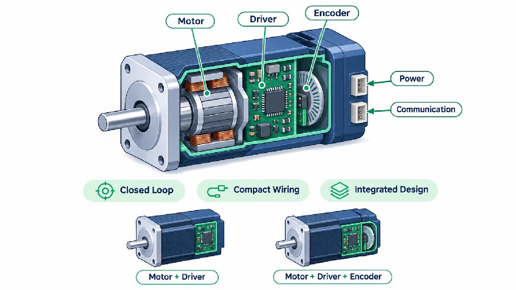
What Is Inside an Integrated Stepper Motor?
A conventional stepper system places the motor on the machine and a separate drive inside a cabinet. Four, six, or eight motor leads, according to motor construction, run between them. The drive receives power and commands and produces controlled phase currents. In an integrated design, the power electronics sit behind or alongside the motor, frequently beneath a rear cover that adds to the overall length.
A typical integrated unit contains a two-phase hybrid stepping motor, MOSFET power stage, current-sense circuitry, microcontroller or digital signal processor, DC-bus conditioning, configuration memory, and external connectors. Closed-loop products add a rotor-position sensor and control algorithms that compare commanded and measured motion. Bus-controlled products may also integrate an RS485 transceiver or CAN controller and transceiver.
Simplified functional arrangement (not a product pinout):
PLC / Motion Controller / Host Computer
             |
    Pulse/Direction, RS485, or CANopen
             |
   +-----------------------------+
   | Integrated Motor Assembly   |
   | Communications + Control    |
   | Motion Planner / Protection |
   | Power Driver / Current Loop |
   | Stepper Stator + Rotor      |
   | Encoder (closed-loop only)  |
   +-----------------------------+
             |
       Shaft / Coupling / Load

Separate connections: DC power; optional DI/DO;
protective bonding and shielding as specified.
The diagram is conceptual. Connector pin numbers, electrical logic levels, isolation barriers, and the number of I/O signals vary between products. No technician should infer a terminal assignment from this illustration.
Integration does not eliminate the need for a power supply, controller, home sensors, safety circuit, and suitable cables. It primarily changes where drive electronics are mounted and how commands are conveyed. The resulting system can be compact, but local electronics now operate close to motor heat and mechanical vibration.
Motor + Driver Versus Motor + Driver + Encoder
The phrase integrated stepper motor with driver covers several architectures that should not be confused.
| Architecture | Main components | What it can observe | Typical control strengths | Important limitation |
|---|---|---|---|---|
| Open-loop integrated stepper | Motor + driver, sometimes local motion controller | Commanded steps, electrical protection, perhaps estimated load indicators | Low complexity, predictable indexing under suitable load | No direct confirmation that the shaft followed every command |
| Closed-loop integrated stepper | Motor + driver + encoder + feedback control | Actual rotor position and tracking error, subject to firmware | Better load-disturbance detection; adaptive current and fault reporting where supported | Encoder feedback does not remove torque or speed limits |
| Networked integrated closed-loop stepper | Motor + driver + encoder + communication controller | Position, status, faults, and other mapped variables | Distributed diagnostics, parameterization, multi-axis network integration | Real-time and interoperability depend on protocol, firmware, and master |
| Integrated motor with gearbox or brake | One of the above plus mechanical accessories | Depends on feedback location and brake monitoring | Increased output torque or holding capability | Backlash, efficiency, brake control, and overall length matter |
Open-loop systems are not inherently inaccurate: a correctly sized stepper can hold position and repeat movement very well. Their weakness is that a disturbance may create an undetected position error. Conversely, a closed-loop label does not make a stepper equivalent to an industrial AC servo in every respect. Steppers retain characteristic torque-speed behavior, resonance concerns, rotor inertia, and thermal constraints.
What an Encoder Really Adds
Encoders provide feedback, but the marketing terms resolution, accuracy, and repeatability describe different things. Resolution is the granularity of a reported position. Absolute accuracy is how closely that reading corresponds to the true physical angle. Repeatability is the ability to return to a prior position under the same conditions. Backlash, flexure, microstepping nonlinearity, and load dynamics can dominate total axis error even when the encoder has many counts per revolution.
For example, a 17-bit single-turn position word has 131,072 discrete codes per revolution if all 17 bits are used to represent angular position. That is a nominal code interval of approximately 0.00275°, not a guarantee of 0.00275° absolute shaft accuracy. Published FRANK HU MOTOR STM product listings describe 17-bit absolute magnetic encoders, while a related manufacturer's STM42-M series documentation uses different encoder terminology. Buyers should request the exact encoder definition, calibration accuracy, whether the data is single-turn or multi-turn, and how the count is exposed to the host before using the figure in a specification.
Why Machine Builders Choose Integration—and Why Some Do Not
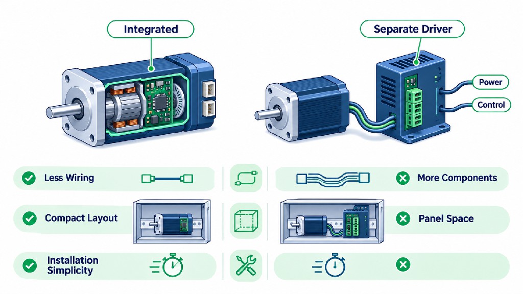
For a compact benchtop analyzer, the traditional motor-to-driver cable may need to cross a moving cable chain and enter a control cabinet. A rear-mounted integrated driver avoids that external high-current motor-phase cable. In a repetitive assembly machine with eight small actuators, the saved cabinet volume and wiring work can be meaningful. Networked units also allow the controller to address individual axes without providing separate pulse generators for each one.
Integration improves the system architecture, not necessarily every individual performance metric. Its value must be evaluated across production, reliability, service, and thermal design.
| Evaluation factor | Integrated motor with driver | Separate motor and driver |
|---|---|---|
| External motor-phase wiring | Usually eliminated outside the assembly | Required between motor and driver |
| Cabinet space | Often lower | Drive hardware needs cabinet space |
| DC power and control cables | Still required | Required at the driver, plus motor cable |
| Thermal management | Electronics share the motor environment | Driver can be cooled in a controlled cabinet |
| Driver replacement | May require replacing or servicing the assembly | Driver can often be replaced separately |
| Motion-network integration | Convenient when a bus interface is built in | Depends on chosen external drive |
| Motor/driver matching | Usually engineered together | Offers more freedom but needs verification |
| Harsh-environment exposure | Driver is near dust, coolant, vibration and motor heat | Drive can be sheltered remotely |
| Long-distance motor placement | Commands and DC power can be distributed | Long motor cables may require EMC precautions |
| Product flexibility | Limited to available integrated combinations | Broad selection of motor and drive pairings |
A useful commercial comparison is total installed cost, not the sticker price of one motor. A simplified engineering estimate is:
Installed axis cost = motor + driver + cable assemblies + controller I/O + installation labor + cabinet allocation + commissioning + expected service cost.
These cost categories are a budgeting framework, not published market averages. The integrated option may cost more per motor but save assembly labor or cabinet components. On the other hand, replacing an entire integrated assembly after an electronic fault can cost more than swapping a separate drive.
When a Separate Driver Is the Better Choice
A separate drive is attractive when the motor sits beside a hot spindle, vacuum chamber, washdown process, or high-vibration assembly; when cabinet-level drive cooling is available; when the engineer needs a specialized supply or current range; or when the axis must be serviced without removing the motor. It can also be preferable when a multi-axis controller already has abundant pulse outputs and the architecture is well proven.
A practical decision rule is to choose integration when wiring density, distributed control, space, and consistent assembly dominate, and to consider separation when thermal isolation, modular service, or unusual motor/drive matching dominates. Neither conclusion should be made without the actual duty cycle and torque-speed curve.
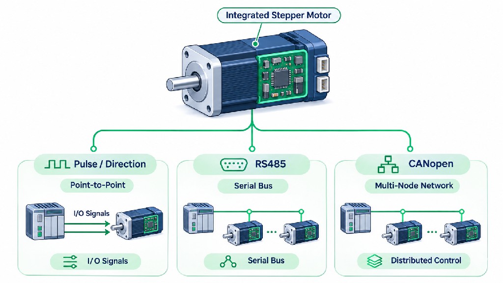
Pulse/Direction, RS485, and CANopen: Three Different Control Approaches
The interface is as important as torque. It determines what the host must generate, which cables are needed, how several motors are coordinated, and what diagnostic data can return to the machine controller.
Pulse/Direction: Simple, Deterministic Commanding
A Pulse/Direction input typically receives a train of step pulses and a direction level. Its host could be a PLC high-speed transistor output, CNC motion card, or dedicated step generator. The number of command pulses represents movement; pulse frequency sets commanded speed. A separate enable input may exist. Some products support CW/CCW pulse arrangements rather than Pulse/Direction, or allow selection between them.
For a 1.8° motor, one revolution has 200 full steps. With a commanded resolution of 16 pulse increments per full step, 3,200 input pulses represent one motor revolution when the configured electronic gearing corresponds to that assumption. A commanded 600 rpm then requires 32,000 pulses per second: 3,200 × 600 / 60. This is an illustrative calculation; the actual pulse interpretation must match the drive's input gearing and pulse-frequency rating.
Pulses are straightforward for a controller designed around real-time step generation. However, a pulse line does not automatically communicate actual position, following error, temperature, or alarm history back to the PLC. Additional I/O or a communications channel may be needed. Confirm voltage thresholds, optocoupler requirements, input type, maximum frequency, minimum pulse width, direction setup/hold time, and grounding before wiring.
RS485: The Electrical Transport, Not the Command Language
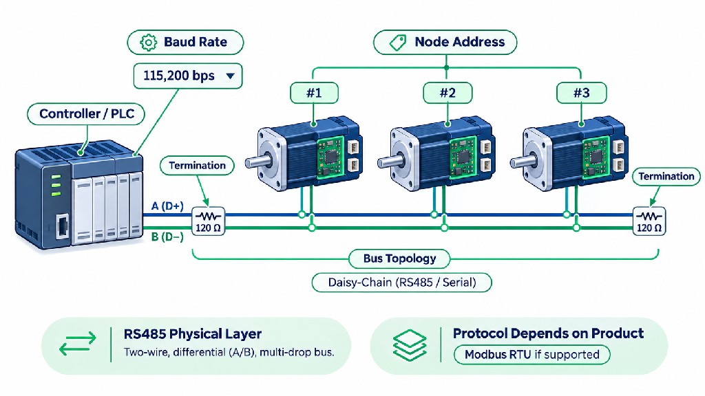
RS485 specifies balanced differential electrical signaling. In a common two-wire, half-duplex installation, multiple devices share a pair of conductors and transmit at separate times. The host typically uses a serial port or USB-to-RS485 interface. An integrated RS485 stepper motor may listen for address-specific commands to move, stop, set speed, read position, or report faults.
The presence of RS485 terminals does not prove Modbus RTU support. To make an RS485 motor work with a Modbus RTU PLC, the device must implement the compatible RTU protocol and publish register addresses, function codes, data formats, and timing requirements. A motor using proprietary serial frames may require a special PLC library or gateway even though both products use RS485 transceivers.
The distinguishes Modbus application-layer messaging from underlying physical networks. Its also provides the serial-line implementation guide for new Modbus designs.
CANopen: Network Communication with Defined Motion Objects
CANopen runs on a CAN-based network and adds a standardized application layer: device configuration, network management, process data, diagnostics, and profiles for different equipment classes. On a CANopen network, the host is generally an NMT manager and SDO client, while each drive is a CANopen device with its own node ID. Cyclic or event-driven PDOs exchange operational data. SDOs access configuration and less time-critical object entries. Emergency objects and heartbeat mechanisms help diagnose device and communication conditions.
For motion systems, CiA 402 is the important drive and motion-control profile. It defines a drive state machine, a controlword and statusword, and a framework for operation modes. The official notes that even devices claiming profile support may implement only a subset of functions. That makes the exact object dictionary and EDS file essential procurement documents.
Side-by-Side Interface Comparison
| Criterion | Pulse/Direction | RS485 with documented Modbus RTU | CANopen |
|---|---|---|---|
| Command format | Pulse timing and discrete logic | RTU serial requests, function codes and device registers | CANopen objects, NMT, SDO, PDO, and device profiles |
| Typical host | Step generator or PLC high-speed outputs | PLC serial master, PC, embedded host | CANopen-capable PLC, industrial controller, CAN host |
| Axis addressing | Usually dedicated pulse signals per axis | Device address in serial messages | CANopen node ID |
| Position/velocity command | Encoded through pulses and frequency | Register-dependent | Profile/vendor object-dependent |
| Feedback availability | Optional separate I/O | When registers and functions are provided | When status objects/PDOs are implemented |
| Multi-axis scaling | More pulse output channels or motion hardware | Shared serial bus with polling | Shared CAN bus with prioritized frames and PDOs |
| Motion timing | Host-generated pulse timing | Request/response scheduling and local motion planning | Bus arbitration plus supported synchronous/event-driven functions |
| Setup data | Input gearing, pulse polarity, limits | Address, baud, framing, register map | Node ID, bit rate, EDS, PDOs and profile settings |
| Main integration risk | Pulse timing and input compatibility | Assuming RS485 equals Modbus | Assuming CANopen equals full CiA 402 feature set |
If a machine only needs to index one axis using an existing motion card, Pulse/Direction may be the fastest solution. If a compact PLC has a supported Modbus RTU master and controls several low- to moderate-update-rate actuators, RS485 may be economical. If the project needs structured multi-axis status, standardized network management, and planned expansion, CANopen deserves serious consideration—provided the motor and host implement compatible features.
CANopen vs Modbus RTU: The Protocol-Layer Difference
It is tempting to treat CANopen and Modbus RTU as interchangeable names for a serial motor network. They solve some similar industrial tasks, but their message models and integration processes differ significantly.
Modbus RTU normally uses a request/response pattern. A client (historically called the master) sends a function code and addressing information to a server (historically the slave). The server returns requested register values or an acknowledgment, or an exception response. The RTU frame includes a cyclic redundancy check, or CRC. Common commands include Function Code 03 for reading holding registers, 04 for input registers, 06 for writing one holding register, and 16 (0x10) for writing multiple registers. Not every motor supports all of them. A 32-bit position target may span two 16-bit registers, and the byte/word ordering must be confirmed.
CANopen uses the CAN data-link protocol with an object dictionary and multiple communication services. SDOs read and write defined objects; PDOs carry operational process data efficiently when mapped; NMT manages node communication states; and heartbeat or other supported error-control mechanisms monitor node presence. In a motion profile implementation, dedicated objects can represent target position, actual position, controlword, statusword, homing configuration, and operating mode.
| Protocol detail | Modbus RTU over RS485 | CANopen over classic CAN |
|---|---|---|
| Physical transport | Commonly two-wire RS485; others possible by protocol design | CAN physical layer, normally a differential CAN_H/CAN_L pair |
| Typical communication | Client polls or writes a server | PDO exchange, SDO access, NMT, heartbeat and emergency messaging |
| Logical addressing | Modbus server/unit address | CANopen node ID plus CAN identifiers and object indexes |
| Data model | Coils, discrete inputs, input registers and holding registers | Object dictionary with index/subindex, data types and access rights |
| Basic error checking | RTU frame CRC | CAN frame-level error detection plus CANopen error mechanisms |
| Device description | Vendor register map and protocol manual | EDS/DCF, object dictionary and supported profile documentation |
| Motion standardization | No universal Modbus RTU stepper motion register map | CiA 402 provides a common framework if implemented |
| Scheduling | Host polling and serial turnaround | CAN arbitration and configured PDO/event or synchronization behavior |
| Interoperability limit | Matching serial settings is insufficient without a register map | Matching CAN bit rate is insufficient without compatible CANopen profiles |
A buyer should therefore ask a protocol-specific question, not merely “Does it have a bus?” For RS485: Which serial application protocol, register map revision, parity setting, and endianness are implemented? For CANopen: Which CiA 301 services and CiA 402 modes, EDS entries, PDO mappings, and NMT behavior are supported?
A Practical RS485 Polling Calculation
Communication capacity is often misunderstood. Consider an illustrative Modbus RTU bus running 115,200 bit/s, with 8 data bits, no parity, and 1 stop bit (8N1). A transmitted byte then takes 10 serial bits. If one request is 8 bytes and its response is 9 bytes, their combined wire time is approximately:
(8 + 9) bytes × 10 bits/byte ÷ 115,200 bits/s = 1.48 ms
That 1.48 ms is only ideal transmission time, not transaction time. RTU interframe silence, device processing, turnaround, serial-adapter behavior, PLC scan time, retries, and the drive's own motion planner add delay. A controller polling eight axes sequentially has to budget all eight transactions, not simply one. Larger reads, 32-bit variables, and slow drives make the cycle longer.
The implication is practical: Modbus RTU can work well for point-to-point moves where the drive locally generates acceleration and deceleration. It is much less suitable for an application that expects the host to stream tightly synchronized trajectory setpoints at a high update rate unless the complete system has been designed and validated for that purpose.
CANopen Timing Is Also Not Automatically Synchronized Motion
CAN arbitration prioritizes certain message identifiers, and properly configured PDOs can carry frequent status and commands. CANopen systems may use SYNC-related communication, but a CANopen connector alone does not guarantee cyclic synchronous positioning, deterministic cross-axis interpolation, or microsecond-level simultaneity. Those features require compatible operating modes, configured periods, supported device firmware, sufficient bus capacity, and a capable master.
Consult for published bit-rate and bus-length relationships. Its illustrative classic-CAN table gives 500 kbit/s at a 100 m network length and 1 Mbit/s at 25 m, subject to the specified physical design and assumptions. These are network design figures, not guaranteed cable lengths for a particular STM motor; the product manual and real wiring environment take precedence.
Node IDs, Baud Rates, Termination, and Bus Topology
A reliable network begins with correct physical installation. Most motor communication failures at commissioning are not sophisticated software bugs: they come from incorrect polarity, inconsistent transmission settings, duplicate addresses, loose cable shields, excessive stubs, missing termination, or power supply disturbances.
Assigning Addresses
Each addressable device on a single network must have a unique identifier. On Modbus RTU, ordinary addressed servers generally use addresses 1–247, with address 0 reserved for broadcast. These represent protocol address possibilities, not a promise that 247 physical devices can operate on one RS485 trunk. Actual node count depends on transceiver loading, cable design, permitted protocol timing, and equipment limits.
Classic CANopen networks commonly use node IDs 1–127 for devices. ID 0 has special management use and is not an ordinary drive node identifier. A successful commissioning record should map the mechanical axis name to the exact hardware ID, serial number, firmware, selected protocol and bit rate. Record this mapping on the electrical schematic as well as in the PLC project.
Assign addresses before powering every axis together. Two motors at the same factory-default address can produce confusing responses on RS485 and interfere with expected CANopen traffic. Address changes may require a restart, special command, or nonvolatile save operation depending on firmware.
CANopen Wiring Topology
Illustrative CANopen trunk (NOT an STM connector pinout)

CAN_H ----+----------+--------------+--------------+-----
          |          |              |              |
        [120Ω]   CAN master      Motor node 1    [120Ω]
          |          |              |              |
CAN_L ----+----------+--------------+--------------+-----
                                     (more nodes may be on
                                      the trunk between ends)

Resistors bridge CAN_H to CAN_L at the two physical ends.
Keep node drops short; observe shielding, signal reference,
bonding and isolation requirements in the device manuals.
In the conceptual drawing, the two 120-ohm terminations bridge CAN_H and CAN_L at the two physical ends of the trunk; the layout is abbreviated to show the devices. A motor in the middle of the trunk normally should not add another end termination. Some devices provide a built-in switchable resistor; others need an external resistor. Verify before adding one.
Use a linear trunk rather than a star of long branches. Keep stubs short, match all devices to the configured bit rate, and choose cable and shield practices suitable for the environment. CAN_H and CAN_L should never be connected directly to DC supply terminals. A CAN controller is not the same thing as a CANopen master: raw CAN frame support does not provide CANopen services automatically.
RS485 Wiring Topology
Illustrative two-wire, half-duplex RS485 trunk

Pair 1 ----+-----------+--------------+-------------+----
           |           |              |             |
          [RT]      PLC / host       Motor 1        [RT]
           |           |              |             |
Pair 2 ----+-----------+--------------+-------------+----
                                      (additional motor nodes
                                       may share the trunk)

RT bridges the pair at the two physical ends only.
A/B labels vary by manufacturer; confirm actual polarity.
Provide required bias, signal reference and shielding.
Here RT means a termination resistor across the differential pair at a physical bus end, usually chosen to match the cable's characteristic impedance, commonly 120 ohms. Texas Instruments explains the transmission-line basis in . Do not automatically enable every motor's termination switch or install a resistor at each spur.
Unlike CAN_H/CAN_L labels, manufacturers' use of A, B, D+, and D- is notoriously inconsistent across RS485 equipment. Identify the non-inverting/inverting pair using the manuals for both the host and motor; do not assume matching letters mean matching polarity. Some buses also require an intentional signal common and a single properly designed bias network. Isolation, protective bonding, surge protection, shield grounding, and ground-potential differences need evaluation by a qualified machine electrician.
Network Commissioning Checklist
-
Disconnect power and confirm the motor's exact connector drawing and cable pinout.
-
Identify the two physical ends of the trunk; check termination switches and external resistors.
-
Check each axis has a unique node/server address and compatible bit rate.
-
For RS485, match parity, stop bits, protocol framing and register-map revision.
-
For CANopen, load the correct EDS and verify NMT, heartbeat and supported objects.
-
With power removed, verify continuity and the absence of wiring shorts. A resistance reading around 60 ohms across a CAN trunk can suggest two parallel 120-ohm end resistors, but other circuit elements can alter the result; it is a diagnostic clue, not an acceptance test.
-
Start with one motor, confirm communication, then add devices one at a time.
-
Check communications under real movement, with nearby contactors, braking loads, and other noise sources active.
-
Record the as-built IDs, parameters, cable lengths, and firmware revisions.
FRANK HU MOTOR STM Selection and Function Compatibility Matrix
The lists compact closed-loop integrated stepper-servo units in paired RS485 and CANopen versions. The product descriptions identify the original equipment manufacturer as NiMotion. The published catalog spans small NEMA 8 units through NEMA 23 models, covering low-torque instrument axes and larger automation axes.
The following figures are published holding-torque and nominal-voltage descriptions, not continuous torque at operating speed. A model suffix ending -485 represents the cataloged RS485 variant; -CANopen represents the separately listed CANopen variant. Those are catalog labels, not a statement that both interfaces work simultaneously on one purchased unit.
| STM model family / example suffixes | Frame | Published holding torque | Listed nominal supply | Published interface variants | Intended first-look application |
|---|---|---|---|---|---|
| STM2038B-485 / -CANopen | NEMA 8 / 20 mm | 0.04 N·m | 24 VDC | RS485 or CANopen SKU | Miniature positioning and instrument mechanisms |
| STM2832B-485 / -CANopen | NEMA 11 / 28 mm | 0.05 N·m | 24 VDC | RS485 or CANopen SKU | Compact optical or laboratory motion |
| STM2851B-485 / -CANopen | NEMA 11 / 28 mm | 0.10 N·m | 24 VDC | RS485 or CANopen SKU | Small feed and adjustment axes |
| STM3528B-485 / -CANopen | NEMA 14 / 35 mm | 0.16 N·m | 24 VDC | RS485 or CANopen SKU | Compact lab and inspection modules |
| STM3548B-485 / -CANopen | NEMA 14 / 35 mm | 0.40 N·m | 24 VDC | RS485 or CANopen SKU | Higher-load miniature automation |
| STM4234B-485 / -CANopen | NEMA 17 / 42 mm | 0.28 N·m | 24 VDC | RS485 or CANopen SKU | Small XY and pick-and-place axes |
| STM4240B-485 / -CANopen | NEMA 17 / 42 mm | 0.40 N·m | 24 VDC | RS485 or CANopen SKU | Instrument and light indexing axes |
| STM4248B-485 / -CANopen | NEMA 17 / 42 mm | 0.50 N·m | 24 VDC | RS485 or CANopen SKU | Automated dispensing and handling |
| STM4260B-485 / -CANopen | NEMA 17 / 42 mm | 0.70 N·m | 24 VDC | RS485 or CANopen SKU | Higher-torque compact positioning |
| STM5756B-485 / -CANopen | NEMA 23 / 57 mm | 1.20 N·m | 48 VDC | RS485 or CANopen SKU | Medium-duty handling and transfer |
| STM5776B-485 / -CANopen | NEMA 23 / 57 mm | 1.90 N·m | 48 VDC | RS485 or CANopen SKU | Medium-duty automation |
| STM57B5B-485 / -CANopen | NEMA 23 / 57 mm | 3.00 N·m | 48 VDC | RS485 or CANopen SKU | Higher-torque NEMA 23 applications |
Source: individual STM listings and the catalog pages above, checked November 2026. Some model lengths, connector versions, encoder descriptions, and operating ranges differ. Confirm the exact part number and current drawing before purchasing. A 24 V or 48 V listing is a nominal designation; it does not describe the entire permitted DC input window.
For specific reference points, the lists 12–36 VDC input, 0.4 N·m holding torque, a 42 × 42 mm flange, and 58.5 mm overall body length. The presents the CANopen variant. The lists 16–52 VDC, 1.2 N·m holding torque, and a 57 × 57 mm flange. These specific supply ranges must not be applied to every STM model.
What Can—and Cannot—Be Claimed About STM Functional Compatibility
| Function or property | STM -485 product listing |
STM -CANopen product listing |
What to obtain before PLC integration |
|---|---|---|---|
| Integrated motor and drive | Listed | Listed | Exact motor/drive revision |
| Closed-loop encoder feedback | Listed; encoder described as absolute | Listed; encoder described as absolute | Encoder specification, resolution definition, accuracy and position retention |
| Physical/advertised network | RS485 | CANopen | Connector pinout, cable specification and interface isolation |
| Modbus RTU protocol | Not established solely by RS485 label | Not applicable by CANopen label | RS485 protocol manual, supported function codes and register map |
| CiA 402 state machine and modes | Not implied by RS485 | Verify per CANopen model and firmware | EDS/DCF, object dictionary and supported mode list |
| Position and speed commands | Depends on implemented serial command set | Depends on implemented objects and modes | Units, scaling, limits, motion command examples |
| Homing and limit-input functions | Model/firmware-dependent | Model/firmware-dependent | I/O diagram, homing methods and sequences |
| Alarm reporting / fault reset | Model/firmware-dependent | Model/firmware-dependent | Error table, fault recovery, watchdog behavior |
| PDO and SYNC support | Not part of Modbus RTU | Verify supported PDO maps and timing | EDS, PDO configuration, master compatibility |
| Braking, STO, safety rating | Not implied | Not implied | Brake SKU, safety documentation and machine risk assessment |
The related describes CANopen/RS485 options, magnetic encoder feedback, I/O and a set of CiA 402 modes for that manufacturer series. It is useful engineering context, but it is not proof that every FRANK HU MOTOR catalog suffix or firmware build supports every listed manufacturer-series function. In particular, the FRANK HU MOTOR website's “Modbus Mode: RS485” or “Modbus Type: CANopen” field labels should not be interpreted as a verified protocol declaration without the relevant manual.
How to Narrow Down the Product Family
Start with mechanics, then communications. A NEMA 17 integrated stepper motor fits the general 42 mm flange class, but that does not guarantee interchangeability with another NEMA 17 unit. Compare flange holes, shaft diameter, shaft length, total depth including electronics, connector clearance, cable exit direction, allowable radial/axial loading, and heat-sinking surface. Confirm whether any absolute encoder requires a battery to retain multi-turn information, and whether power cycling preserves the application's coordinate reference.
An STM42 model can be a strong candidate for small laboratory equipment or dispensing axes. An STM57 model may fit a larger handling axis, but only if the dynamic torque-speed curve, motor inertia, and thermal measurements pass. Some customers instead need a conventional integrated closed-loop drive with Pulse/Direction commands; FRANK HU MOTOR also lists ESS and iHSS examples in its . Do not assume an ESS, iHSS, or another “integrated” model includes CANopen or Modbus RTU unless its individual specification says so.
How to Size an Integrated Stepper Motor Correctly
The most common selection error is choosing a motor from holding torque alone. Holding torque is a low-speed or stationary rating under specified drive conditions. Torque normally changes with speed as winding inductance, supply voltage, driver current, load inertia and control strategy interact. A motor capable of holding a stationary load may stall while trying to accelerate that same load.
Begin with the load profile: travel distance, cycle time, peak and continuous speed, load mass, drive efficiency, friction, acceleration, external forces, duty cycle and orientation. Then estimate required torque at the motor shaft.
For a rotary axis, a useful first-order relation is:
T_required = T_load + J_total × alpha + T_friction
where T is torque in N·m, J_total is total inertia reflected to the motor shaft in kg·m², and alpha is acceleration in rad/s². This simplified model excludes several real effects, including compliance, resonance, motor detent and losses beyond the chosen friction term.
For a screw-driven linear axis with axial force F, screw lead L in meters per revolution, and total mechanical efficiency eta, the steady driving torque approximation is:
T_screw = F × L / (2 × pi × eta)
For an illustrative 100 N axial force, 5 mm lead and 85% assumed efficiency, the calculated steady torque is about 0.094 N·m. That value is not an adequate finished motor rating. Add acceleration, inertia, seal/friction variation, duty-cycle effects, safety margin and the required torque at actual running speed. Ball screws are often backdrivable; a vertical axis may need an appropriately designed brake or counterbalance independent of the motor's holding torque.
For another example, suppose a rotary axis calculation gives 0.18 N·m load and friction torque plus 0.07 N·m acceleration torque. The first-order peak demand is 0.25 N·m. Applying an illustrative 1.5 design factor produces a target of 0.375 N·m available at the relevant speed. A model advertised with 0.4 N·m holding torque cannot automatically be judged sufficient. Request the torque-speed curve at the chosen DC voltage, actual operating current and ambient conditions, and confirm the available dynamic torque at the most demanding point of the cycle.
Electrical and Mechanical Questions Before Purchasing
| Requirement | Data to establish | Why it matters |
|---|---|---|
| Running speed | Peak rpm and duration | Determines torque available away from standstill |
| Peak torque | Load, acceleration and friction | Prevents stalls or excessive tracking error |
| Duty cycle | Motions per hour and time at current | Determines heating and usable continuous performance |
| Inertia | Rotor, coupling, gear and reflected load | Influences acceleration, settling and resonance |
| Mechanical interface | Flange, shaft, flat, coupling and overall length | Avoids mounting and clearance problems |
| Power | Allowed voltage range and transient current | Prevents undervoltage and overvoltage faults |
| Feedback | Encoder type, accuracy and homing strategy | Determines position verification and restart behavior |
| I/O | Home, limits, enable, alarm and brake signals | Controls safe sequence and external interlocks |
| Protocol | Pulse, exact RS485 language, or CANopen functions | Determines PLC/controller compatibility |
| Environment | Ambient temperature, cooling, ingress exposure | Determines electronics reliability and derating |
A higher DC supply voltage often improves high-speed current rise for a compatible stepper drive, but never exceed the integrated unit's specified input range. The controller, thermal design and electronics may impose limits very different from a bare stepper motor's coil specifications. Higher commanded speed does not increase an axis's mechanically safe maximum rpm, and acceleration must remain inside the torque envelope.
Power Distribution, Heat Management, and Protection
A smart motor is still an electromechanical load. Its integrated electronics need a stable, correctly protected DC source, and their heat must be conducted and convected away within the approved environmental limits.
Designing a DC Supply
Use the individual product's specified input voltage window, not the nominal family voltage alone. For example, the published STM4240B listing gives 12–36 VDC and the STM5756B listing gives 16–52 VDC. Supply ratings must be checked at the motor terminals under loaded operation, not only at the power supply's output while idle.
A supply must provide sufficient current for the expected simultaneous demand of the axes, input charging and control electronics without unacceptable voltage sag. The motor's listed rated phase current is not necessarily equal to its DC bus input current. Avoid simply multiplying the phase-current numbers and treating the result as a verified supply requirement. Obtain input-power data or measure representative worst-case operation while observing the supplier's recommendations.
Regeneration also matters. During deceleration, a driven motor and mechanical load can return energy toward the DC bus. Depending on the drive's internal design, this can raise bus voltage and trigger an overvoltage alarm. The system may need a suitable supply, energy-management circuit, braking arrangement or modified deceleration profile. Never assume an integrated stepper includes a braking resistor or that all switching supplies can absorb regenerated energy.
Illustrative Power Wiring Architecture
             Protected AC supply
                     |
             Approved DC PSU
                     |
        DC distribution / fusing
             +-------+-------+
             |               |
          Axis 1           Axis 2
       DC+ / DC-        DC+ / DC-
          |                  |
    Integrated motor   Integrated motor

  Separately: PLC communication and safety-related
  interlocks, bonding/shielding per equipment manuals.
This is a system concept, not a connector wiring diagram. Polarity, fuse ratings, wire sizes, grounding points, allowable supply ripple, surge clamping, I/O voltage and required power-up sequence must come from the specific manual and the machine electrical design. Never connect or disconnect a motor's power or communications connectors under load unless the device is explicitly rated for hot plugging.
Thermal Design for an Integrated Drive
The motor frame, internal power stage, control PCB and encoder share a restricted physical volume. Even a correctly sized motor can fail an application if installed against insulating plastic, enclosed without ventilation, or operated continuously at high torque. Motor exterior temperature and electronics temperature are not identical; a warm housing does not by itself prove a defect, and a housing temperature below a generic number does not guarantee internal components are safe.
Bolt the unit to a mechanically sound mounting surface that can provide appropriate heat conduction where recommended. Leave clearance for cable bends and ventilation. Avoid placing connectors where coolant, aggressive solvents or conductive dust can enter. Confirm the manufacturer's ambient temperature rating, ingress protection, vibration specifications and any thermal derating curves for the exact variant. The related manufacturer's STM42-M literature, for example, specifies an operating temperature range for that series, but the actual purchased SKU's documentation governs.
A useful validation test runs the axis through the real production cycle until temperatures stabilize. Measure the housing or defined test points, monitor faults and supply voltage, and log ambient temperature. Repeat at maximum anticipated throughput, with the enclosure closed and neighboring heat-producing equipment operating. If the drive reports internal temperature, confirm what sensor and scaling that measurement represents.
Machine Safety Is Separate From Communication
A CANopen stop command, Modbus register write, or pulse enable line must not be treated as a certified safety function unless the entire relevant system has been assessed and documented accordingly. A communication timeout, stalled controller, welded contactor or failed power stage can defeat ordinary software expectations. Design emergency stopping, guarding, vertical-axis load retention, safe torque-off where genuinely provided and certified, and restart interlocks from the machine risk assessment. Do not claim STM devices have STO or safety-rated braking unless the exact datasheet provides such evidence.
Position, Velocity, Homing, and Alarm Control
Applications generally need four types of behavior: move to a position, rotate at a speed, establish a coordinate origin, and react predictably to faults. The protocol determines how commands are represented, while drive firmware determines which behaviors exist.
Position Moves
A point-to-point position instruction should specify absolute or relative motion, target units, speed limits, acceleration/deceleration, and what signals indicate motion completion. With Modbus RTU, these details are often stored in vendor-defined registers and invoked through a command bit or register. With CANopen and a compatible CiA 402 implementation, they may be mapped to profile-defined objects; for example, object 0x607A is commonly used for target position in Profile Position applications. Those object numbers are not proof a particular motor implements the associated mode.
The host should distinguish command accepted, motor running, target reached, and actual position within tolerance. They are not necessarily the same event. For precision applications, validate settling time and the final mechanical position under external load rather than trusting a single status bit.
Velocity Control
Continuous conveyance, feed rollers and rotating tables often need a speed command rather than repeated short position moves. Typical configuration includes acceleration, speed limit, direction, and stopping behavior. A compatible CiA 402 drive may expose Profile Velocity and use object 0x60FF for target velocity. But raw register units and object scaling vary, and not every STM firmware supports every mode.
A system designer should document whether a stop command produces a controlled ramp, immediate drive disable, or another action. This becomes especially important when the mechanical load is capable of moving under gravity or residual momentum.
Homing and Coordinate Recovery
Homing establishes a useful machine reference. Some axes move to a mechanical home switch; others detect an index event or use a supported absolute-position reference. A typical sequence is to verify safe conditions, move toward the home reference at a controlled speed, detect the transition, back off or approach more slowly if supported, set the coordinate offset, and confirm the result.
CANopen devices implementing the relevant CiA 402 Homing functionality commonly use operation-mode object 0x6060 with a supported mode value, and may use 0x6098 to select a homing method. These are examples of a standard vocabulary—not a substitute for an STM user manual. Verify switch polarity, the physical direction of movement, stop distances, hardware limits, and behavior after a power loss. An encoder labeled “absolute” does not automatically eliminate the need for a homing sequence; retained position, mechanical reference alignment and firmware initialization must be understood.
Status and Alarms
Closed-loop feedback makes diagnostics more useful. Depending on the model, a drive can report measured position, tracking error, undervoltage, overvoltage, overheating, blocked rotor, sensor issues or communication errors. With CiA 402, 0x6040 is the controlword and 0x6041 the statusword; 0x6064 commonly represents position actual value. Device-specific fault codes and enabled status bits still require the manual.
Build alarms into the PLC state machine. On a fault, stop dependent motion, preserve relevant diagnostic data, present an understandable operator message, and require the correct recovery procedure. Blindly sending repeated reset commands can hide a persistent mechanical jam or supply problem. Distinguish a recoverable communication timeout from conditions that require inspection, and validate the restart behavior after a brownout.
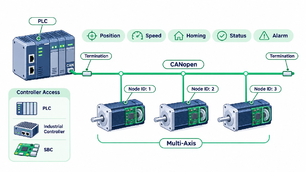
Connecting PLCs, Industrial Controllers, and Single-Board Computers
An integrated motor can simplify the end of an axis, but the host must have the right electrical port and software stack. The table below summarizes typical integration paths.
| Host platform | Pulse/Direction path | RS485 path | CANopen path |
|---|---|---|---|
| PLC | High-speed transistor pulse outputs with suitable electrical interface | Built-in RS485 port or isolated communications module; Modbus RTU master if supported | Native CANopen master or suitable fieldbus module |
| Industrial PC / motion controller | Dedicated motion card or real-time pulse output | USB/PCIe serial interface and correct protocol library | CAN adapter and CANopen master stack |
| Embedded microcontroller | Timer-based pulse generation plus level-compatible output stage | UART plus RS485 transceiver and protocol firmware | CAN controller/transceiver plus CANopen software |
| Linux single-board computer | Dedicated timing hardware or step-generator coprocessor preferred | USB-RS485 adapter and user-space application | Supported CAN interface and CANopen stack; verify real-time requirements |
A general-purpose Linux GPIO toggle loop is not a replacement for a deterministic high-rate step generator. The operating-system scheduler can introduce pulse jitter. Likewise, possessing a CAN peripheral does not automatically make an embedded board a CANopen controller. The application needs the appropriate higher-layer software.
Commissioning Example A: PLC to an RS485 STM Axis
First, confirm from the exact SKU documentation whether the RS485 variant uses Modbus RTU. If it does, obtain the serial settings and register map. If it uses a proprietary protocol, use its documented messages or a supported gateway instead of issuing random Modbus reads.
Commission one drive at a time. Power the motor from a correctly rated DC source; connect the differential pair and required reference through the specified cabling; establish the permitted address and baud setting; and ensure end termination is correct. Use a serial diagnostic tool to make a read-only identification or status query documented for that firmware. Check the reply address, CRC if RTU applies, and returned values.
After verifying communications, confirm external enable, interlocks and travel limits. Issue the smallest practical controlled move at low speed, read actual or reported position, and compare observed physical rotation. Then test both directions, a longer move, expected target-reached behavior, a controlled stop, a limit switch, and a known safe fault-recovery procedure. Record the transaction logs. Only after one axis passes should additional motor nodes be attached.
Commissioning Example B: CANopen STM Axis with an Industrial PLC
Use a PLC with a functioning CANopen master, not merely a CAN transceiver. Obtain the matching EDS file and confirm firmware compatibility. Set a unique node ID and matching bit rate, wire CAN_H/CAN_L with the recommended reference/shield arrangement, and install exactly the correct end terminations. On initial power-up, observe the device boot-up and NMT state according to the manual.
Next, use SDOs to read the expected identity and supported object entries. Configure heartbeat monitoring, any required watchdog, PDO mappings, and the operating mode that the exact drive supports. Where CiA 402 is implemented, drive enabling requires the documented state-machine transitions, not just a single “start” bit. Verify statusword changes before authorizing a move. Command a small, speed-limited position change and confirm actual feedback. Test stop, disable, communication interruption, axis limits, and a safe restart.
For a multi-axis system, do not assume identical default PDO mappings across firmware revisions. Maintain the EDS files with the PLC source and record configured communication objects as part of the machine's released configuration.
Commissioning Example C: Raspberry Pi or Another Linux SBC
A Linux SBC can coordinate laboratory equipment and prototypes, but it generally needs an external RS485 transceiver/adapter or a supported CAN interface. Choose an industrially suitable isolated adapter when ground potential, EMC or serviceability justify it. For RS485, the application must implement the actual motor protocol; a standard Modbus library is useful only when the motor really supports compatible Modbus RTU registers. For CANopen, select a proven CANopen stack and confirm driver-level interface and bus timing.
For safety and reliability, keep fast trajectory generation local to the drive or a dedicated real-time controller where possible. The SBC should supervise and request motions, not depend on a non-real-time user-space process for safety-critical stops. Document reboot behavior, application startup ordering, network-recovery policy and what the motors do if the host software crashes.
Designing a Distributed Multi-Axis Motion System
Distributed motion control is one of the strongest reasons to purchase a smart stepper motor. Instead of routing individual phase cables from a central cabinet to every actuator, each axis has a local driver and shares an appropriate communications backbone. The PLC supervises the sequence, while each node may carry out its own motion planning and protection functions.
Consider a laboratory sample-handling platform with an X transfer axis, Y transfer axis, rotary carousel, pipette lift, and two adjustable clamps. Some axes need only occasional point-to-point movements. Others may need coordinated starts or frequent status updates. Treating all six as identical bus loads would waste engineering effort and could create motion timing problems.
A practical architecture separates axes by their timing requirements:
| Axis role | Example behavior | Engineering priority | Possible communication strategy |
|---|---|---|---|
| Sample clamp | Move between two defined positions | Simple local motion and completion confirmation | Supported Modbus RTU or CANopen point-to-point commands |
| Carousel | Index to a station | Repeatable homing and target-reached signal | Either protocol with documented position feedback |
| Pipette lift | Vertical movement with gravity load | Holding/brake strategy and independent safety analysis | Select by mechanical and safety requirements first |
| X/Y transfer | Coordinated planar moves | Timing, acceleration and trajectory accuracy | Compatible motion profiles/master; verify synchronous support |
| Adjustment screw | Occasional fine positioning | Low-speed control and backlash management | Either bus if suitable |
For this example, a CANopen network may be attractive when the master already supports it and the devices expose compatible PDOs and position-control behavior. RS485 with confirmed Modbus RTU can be sufficient when moves are mostly sequential and the motor performs local acceleration ramps. Neither choice excuses a proper collision-prevention plan or guarantees independent axes move simultaneously.
Coordination Requires an Application-Level State Machine
A multi-axis sequence is more than “send a position to all nodes.” The controller must confirm homing, check whether every axis is ready, establish collision-free motion permissions, issue coordinated commands using the supported interface, watch relevant completion/error feedback, and handle failure of any single node. If one gripper fails to close, for example, the next XY transfer should not proceed merely because the motion command was transmitted.
Where the application needs tightly interpolated movement such as CNC contouring, check whether the exact integrated drive supports the appropriate cyclic or interpolated mode and whether the master and bus bandwidth meet the required servo update rate. If the device only offers local Profile Position moves, a synchronized start does not turn independent profiles into a guaranteed coordinated toolpath. A separate industrial servo network or another drive architecture may be a better match.
Plan for Communication Failure
Every distributed network needs a defined response to a broken cable, failed node, frozen host, or unacceptable delay. For each axis, decide whether the correct response is to decelerate, stop, hold position, disable the power stage, or activate a separate mechanical protection system. These choices depend on machine hazards and the motor's supported watchdog and fault behavior.
CANopen heartbeat supervision can help identify a missing node when properly configured. An RS485 host can implement command/response timeouts and escalate after retries. But an application-level watchdog is not automatically a certified safety function. Validate loss-of-communication behavior with realistic tests, including faults occurring during a move.
Troubleshooting Integrated Stepper Motor Installations
Most first-installation problems can be grouped into communication, power, motion, feedback, and thermal categories. Work methodically and change one variable at a time rather than repeatedly changing address, speed, bus wiring and acceleration together.
| Symptom | Likely investigation areas | Sensible first check |
|---|---|---|
| No RS485 response | Wrong A/B interpretation, address, framing, protocol or missing power | Confirm exact protocol and read-only query using one node |
| Modbus software reports invalid response | Device uses proprietary RS485 protocol, wrong CRC/framing or register map | Obtain manufacturer protocol manual and firmware version |
| CANopen node does not appear | Wrong bit rate, termination, wiring, duplicate node ID or incompatible host stack | Test with one node and a CANopen-capable diagnostic tool |
| Node appears but will not move | Incorrect drive state, enable, selected mode, limits or missing homing | Read status, error and supported mode objects |
| Motion is reversed | Mechanical coordinate convention, direction setting or motor mounting | Test a safe short move at low speed |
| Stalls at high rpm | Insufficient dynamic torque, aggressive acceleration or low DC voltage | Compare requested load to torque-speed curve |
| Unexpected position error | Mechanical slip, backlash, sensor reference or tracking error | Check coupling, encoder feedback and homing repeatability |
| Alarms during deceleration | DC-bus rise, regeneration or unsuitable deceleration | Log supply voltage during the fault and consult supplier |
| Faults after long operation | Heating, enclosure temperature or excessive current demand | Run a stabilized thermal test under realistic duty |
| Intermittent network faults | Long stubs, noise, grounding, loose connections or excess termination | Inspect topology, shields, termination and cable routing |
For CANopen, distinguish a physical-layer failure from a drive state-machine problem. A motor may be visible on the network but not enabled for operation. For RS485, distinguish a completely silent device from a correctly addressed device that rejects a function code. Those differences determine whether to inspect wiring, software protocol, configuration, or the drive's internal status.
A good commissioning report records the original fault, the measured supply voltage, the node address, the bus speed, cable length, controller firmware, motor firmware, test commands, and the confirmed repair. That record reduces service time when a machine is replicated or supported remotely.
Purchasing Checklist: What to Request From FRANK HU MOTOR
A successful B2B inquiry provides enough detail for an engineer to recommend a model and confirm software compatibility before the first sample is shipped. Start with the desired STM frame class and interface, but do not stop there.
Ask for the exact SKU datasheet, torque-speed curve at your planned voltage, dimensional drawing or STEP model, connector pinout, mating cable options, and electrical input/output specification. For an RS485 option, request the protocol name, communication manual, register map, default serial settings, and working read/write examples. For CANopen, request the EDS file, object dictionary, supported CiA 402 modes, PDO details, homing methods, and a working master configuration example. If encoder accuracy is important, request its absolute-accuracy specification rather than relying on a resolution number alone.
For an OEM machine, include target annual quantity, required shaft changes, connector orientation, cable length, mounting constraints, permitted supply voltage, operating temperature, and environmental protection needs. Ask whether the same hardware/firmware revision can be maintained across repeat orders and how changes are communicated. These details are often more valuable than choosing between close holding-torque numbers.
A useful sample request reads as follows:
We are selecting an integrated closed-loop stepper for a multi-axis laboratory platform. Our axis requires [peak torque at rpm], [travel and cycle time], [DC input range], and [operating temperature]. The controller has [CANopen master / Modbus RTU master / pulse outputs]. Please recommend an STM model and provide the exact SKU datasheet, torque-speed curve, wiring diagram, 3D model, communication manual, supported control modes, and a commissioning example. Please also confirm the encoder specification and sample/production revision consistency.
Review the , the wider , or send a technical inquiry through . Confirm an item's current availability, price and lead time directly rather than relying on a previously captured catalog listing.
Frequently Asked Questions
What is an integrated stepper motor?
It is a stepper motor with its drive electronics mounted in the same assembly. Some products also contain an encoder, motion controller, digital I/O and industrial communication electronics. The integrated arrangement reduces external motor-phase wiring but still requires appropriate power, commands, protection and mechanical installation.
Is an integrated closed-loop stepper motor the same as a servo motor?
Not exactly. An integrated closed-loop stepper uses encoder feedback and may employ servo-like control algorithms, which is why some vendors call it an integrated stepper servo motor. Its magnetic construction and torque-speed behavior remain those of a stepper design. Compare the complete dynamic performance, accuracy, settling time, efficiency and temperature requirements against a conventional AC/DC servo solution before substitution.
Does every RS485 stepper motor work with Modbus RTU?
No. RS485 describes the electrical interface, while Modbus RTU is one possible application protocol carried over it. Request the model-specific protocol documentation, including supported function codes and register addresses, before connecting it to a Modbus master.
Can a CANopen stepper motor perform position, velocity and homing moves?
Potentially, yes, but it depends on firmware and supported control modes. The CANopen transport alone does not guarantee implementation of every CiA 402 mode. Confirm the exact EDS, object dictionary, status/control semantics and homing methods for the purchased model.
Do I need a 120-ohm resistor at each motor?
No. In a typical properly designed linear CAN or terminated RS485 trunk, the characteristic-impedance terminations belong at the two physical ends of the trunk, not at every motor. The actual value and termination requirements depend on the cable, interface and application. Follow the equipment's installation manual.
Can several integrated motors share a single power supply?
Yes, when the supply voltage, current capacity, fusing, cable distribution, inrush behavior, regenerative energy and fault isolation have been designed for all connected loads. Separate protection or supplies may be preferable for some machines. Determine the requirements from input-power data and realistic simultaneous-motion tests, not only motor phase-current labels.
Is a NEMA 17 integrated stepper motor suitable for a CNC machine?
It can suit a light-duty positioning or auxiliary CNC axis, provided its torque-speed curve and thermal performance meet the load. NEMA 17 describes a general mounting-frame class, not guaranteed speed, torque, position accuracy or CNC suitability. Larger cutting axes or synchronized contours may demand a different motor and control architecture.
Does a high-resolution absolute encoder eliminate homing?
Not universally. Single-turn versus multi-turn capability, power-loss behavior, absolute alignment, machine-coordinate definition, coupling slip, and firmware initialization all matter. The machine may still need a reference routine or verification sensor, especially after service or a mechanical disturbance.
How do I choose between CANopen and RS485 for a multi-axis machine?
Select from the controller's available protocol stack, axis update requirements, motion synchronization needs, diagnostic expectations, cable topology and confirmed drive capabilities. RS485 with documented Modbus RTU is often practical for locally planned sequential motion. CANopen is attractive for standardized network management and structured motion data, provided the particular devices implement the required functions.
Final Recommendation
The best integrated stepper motor is not necessarily the smallest unit, the one with the highest advertised encoder resolution, or the model with the most communication buzzwords. It is the one that delivers required torque at working speed, survives the actual duty cycle, connects safely to the intended power system, and exposes the precise control and diagnostic functions the host can use.
For machine builders considering FRANK HU MOTOR's STM range, begin with the required NEMA frame and dynamic torque, shortlist the separately listed RS485 and CANopen versions, and request the matching firmware documentation before ordering a development sample. Use a one-axis bench test to validate motion and status behavior, then scale the same tested configuration to the multi-axis system. That approach minimizes avoidable integration delays and gives purchasing, engineering and service teams a common, documented specification.